Page 1182 of 1529

HEATING AND VENTILATION
REPAIRS 80-25
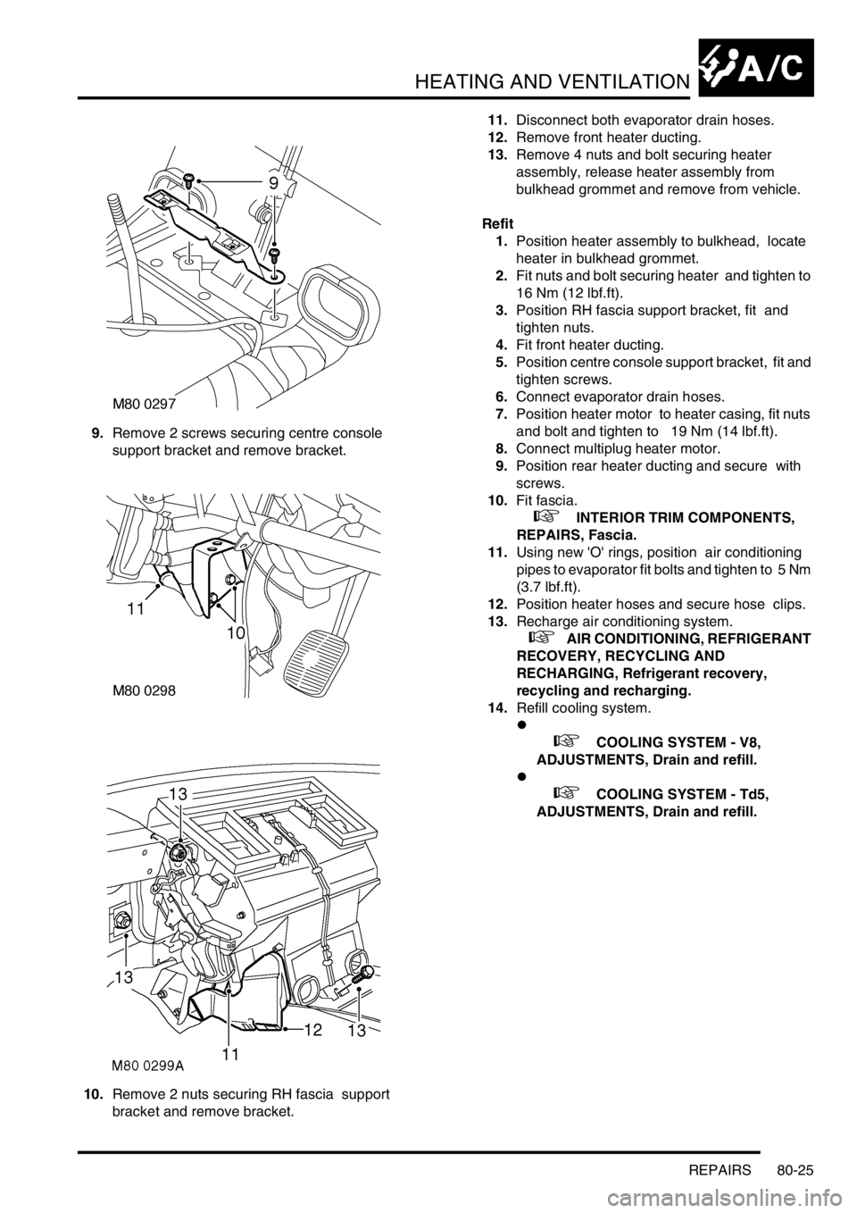
9.Remove 2 screws securing centre console
support bracket and remove bracket.
10.Remove 2 nuts securing RH fascia support
bracket and remove bracket. 11.Disconnect both evaporator drain hoses.
12.Remove front heater ducting.
13.Remove 4 nuts and bolt securing heater
assembly, release heater assembly from
bulkhead grommet and remove from vehicle.
Refit
1.Position heater assembly to bulkhead, locate
heater in bulkhead grommet.
2.Fit nuts and bolt securing heater and tighten to
16 Nm (12 lbf.ft).
3.Position RH fascia support bracket, fit and
tighten nuts.
4.Fit front heater ducting.
5.Position centre console support bracket, fit and
tighten screws.
6.Connect evaporator drain hoses.
7.Position heater motor to heater casing, fit nuts
and bolt and tighten to 19 Nm (14 lbf.ft).
8.Connect multiplug heater motor.
9.Position rear heater ducting and secure with
screws.
10.Fit fascia.
+ INTERIOR TRIM COMPONENTS,
REPAIRS, Fascia.
11.Using new 'O' rings, position air conditioning
pipes to evaporator fit bolts and tighten to 5 Nm
(3.7 lbf.ft).
12.Position heater hoses and secure hose clips.
13.Recharge air conditioning system.
+ AIR CONDITIONING, REFRIGERANT
RECOVERY, RECYCLING AND
RECHARGING, Refrigerant recovery,
recycling and recharging.
14.Refill cooling system.
l
+ COOLING SYSTEM - V8,
ADJUSTMENTS, Drain and refill.
l
+ COOLING SYSTEM - Td5,
ADJUSTMENTS, Drain and refill.
Page 1186 of 1529

HEATING AND VENTILATION
REPAIRS 80-29
Heater matrix
$% 80.20.29
Remove
1.Remove heater assembly.
+ HEATING AND VENTILATION,
REPAIRS, Heater assembly - models with
air conditioning.
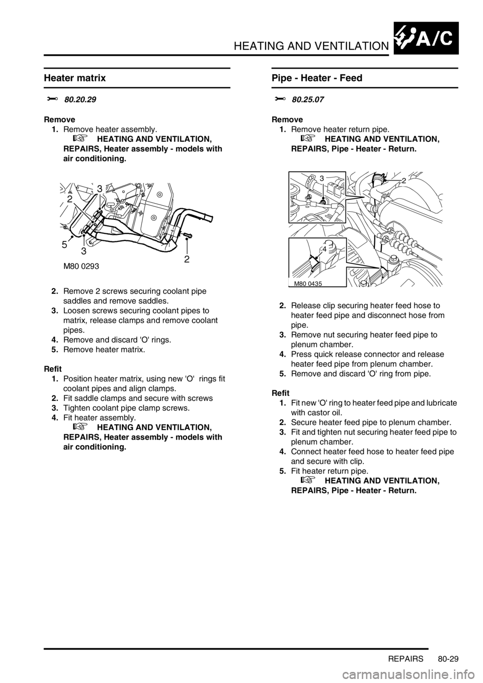
2.Remove 2 screws securing coolant pipe
saddles and remove saddles.
3.Loosen screws securing coolant pipes to
matrix, release clamps and remove coolant
pipes.
4.Remove and discard 'O' rings.
5.Remove heater matrix.
Refit
1.Position heater matrix, using new 'O' rings fit
coolant pipes and align clamps.
2.Fit saddle clamps and secure with screws
3.Tighten coolant pipe clamp screws.
4.Fit heater assembly.
+ HEATING AND VENTILATION,
REPAIRS, Heater assembly - models with
air conditioning.
Pipe - Heater - Feed
$% 80.25.07
Remove
1.Remove heater return pipe.
+ HEATING AND VENTILATION,
REPAIRS, Pipe - Heater - Return.
2.Release clip securing heater feed hose to
heater feed pipe and disconnect hose from
pipe.
3.Remove nut securing heater feed pipe to
plenum chamber.
4.Press quick release connector and release
heater feed pipe from plenum chamber.
5.Remove and discard 'O' ring from pipe.
Refit
1.Fit new 'O' ring to heater feed pipe and lubricate
with castor oil.
2.Secure heater feed pipe to plenum chamber.
3.Fit and tighten nut securing heater feed pipe to
plenum chamber.
4.Connect heater feed hose to heater feed pipe
and secure with clip.
5.Fit heater return pipe.
+ HEATING AND VENTILATION,
REPAIRS, Pipe - Heater - Return.
M80 0435
23
4
Page 1190 of 1529
AIR CONDITIONING
DESCRIPTION AND OPERATION 82-1
AIR CONDITIONING DESCRIPTION AND OPERAT ION
A/C refrigerant system component
layout
Diesel installation shown, V8 similar
1Evaporator and thermostatic expansion valve
2High pressure servicing connection
3To rear A/C system (where fitted)
4Low pressure servicing connection5Refrigerant lines
6Receiver drier
7Condenser
8Compressor
Page 1191 of 1529
AIR CONDITIONING
82-2DESCRIPTION AND OPERATION
A/C control system component layout
RH drive shown, LH drive similar
1Air temperature control ECU
2Heater coolant temperature sensor
3Evaporator temperature sensor
4Dual pressure switch5Ambient temperature sensor
6Sunlight sensor
7In-car temperature sensor
Page 1192 of 1529

AIR CONDITIONING
DESCRIPTION AND OPERATION 82-3
Description
General
The air conditioning system controls the temperature, distribution and volume of air supplied to the vehicle interior to
provide a comfortable cabin environment. The system is electronically controlled and features automatic and manual
modes of operation, with separate temperature control of the LH and RH air outlets. The automatic modes provide
optimum control of the system under most ambient conditions and require no manual intervention. The manual modes
allow individual functions of automatic operation to be overridden, to accommodate personal preferences.
The air conditioning system consists of a refrigerant system, a heater assembly and a control system. It also uses the
same air inlet duct and distribution ducts as the Heating and Ventilation system on non air conditioned vehicles.
+ HEATING AND VENTILATION, DESCRIPTION AND OPERATION, Description.
Fresh or recirculated inlet air flows into the heater assembly from the blower in the air inlet duct. In the heater
assembly, the air is cooled and/or heated, depending on the selected cabin temperature and ambient conditions, then
directed to selected air outlets.
On vehicles with rear air conditioning, additional cooling is provided by recirculating air through a second evaporator
and distributing it to outlets in the roof.
+ AIR CONDITIONING, DESCRIPTION AND OPERATION, Description.
Page 1193 of 1529

AIR CONDITIONING
82-4DESCRIPTION AND OPERATION
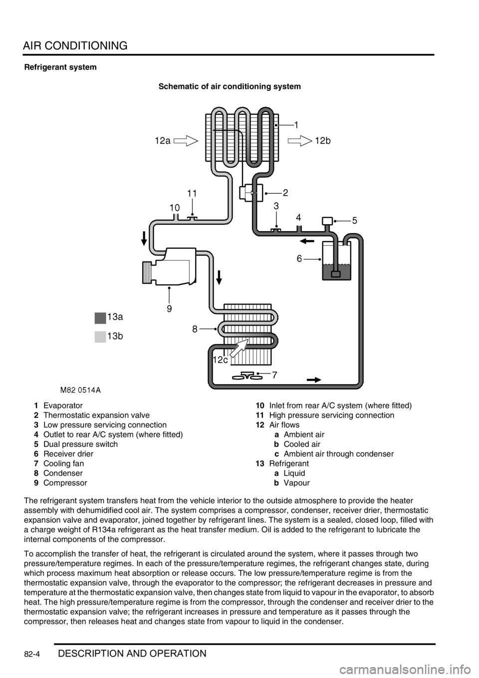
Refrigerant system
Schematic of air conditioning system
1Evaporator
2Thermostatic expansion valve
3Low pressure servicing connection
4Outlet to rear A/C system (where fitted)
5Dual pressure switch
6Receiver drier
7Cooling fan
8Condenser
9Compressor10Inlet from rear A/C system (where fitted)
11High pressure servicing connection
12Air flows
aAmbient air
bCooled air
cAmbient air through condenser
13Refrigerant
aLiquid
bVapour
The refrigerant system transfers heat from the vehicle interior to the outside atmosphere to provide the heater
assembly with dehumidified cool air. The system comprises a compressor, condenser, receiver drier, thermostatic
expansion valve and evaporator, joined together by refrigerant lines. The system is a sealed, closed loop, filled with
a charge weight of R134a refrigerant as the heat transfer medium. Oil is added to the refrigerant to lubricate the
internal components of the compressor.
To accomplish the transfer of heat, the refrigerant is circulated around the system, where it passes through two
pressure/temperature regimes. In each of the pressure/temperature regimes, the refrigerant changes state, during
which process maximum heat absorption or release occurs. The low pressure/temperature regime is from the
thermostatic expansion valve, through the evaporator to the compressor; the refrigerant decreases in pressure and
temperature at the thermostatic expansion valve, then changes state from liquid to vapour in the evaporator, to absorb
heat. The high pressure/temperature regime is from the compressor, through the condenser and receiver drier to the
thermostatic expansion valve; the refrigerant increases in pressure and temperature as it passes through the
compressor, then releases heat and changes state from vapour to liquid in the condenser.
Page 1194 of 1529
AIR CONDITIONING
DESCRIPTION AND OPERATION 82-5
Compressor
1Pulley
2Inlet connection
3Outlet connection4Pressure relief valve
5Clutch connector
The compressor circulates the refrigerant around the system by compressing low pressure, low temperature vapour
from the evaporator and discharging the resultant high pressure, high temperature vapour to the condenser.
The compressor is attached to a mounting bracket on the engine, and is a ten cylinder swash plate unit with a fixed
displacement of 177 ml/rev (0.19 US qt/rev). The auxiliary drive belt drives the compressor via a pulley and an
electrically actuated clutch. Operation of the clutch is controlled by the Engine Control Module (ECM).
To protect the refrigerant system from unacceptably high pressure, a pressure relief valve is installed in the outlet side
of the compressor. The pressure relief valve is set to operate at 34.3 to 41.4 bars (497 to 600 lbf.in
2) and vents excess
pressure into the engine compartment.
Page 1195 of 1529
AIR CONDITIONING
82-6DESCRIPTION AND OPERATION
Condenser
1Condenser matrix
2Outlet connection
3Inlet connection
The condenser transfers heat from the refrigerant to the surrounding air.
The condenser is installed immediately in front of the oil coolers. Rubber mounting bushes are used to mount the
condenser to the chassis sidemembers and brackets on the headlamp panels.
Ambient air, passing through the condenser matrix due to ram effect and/or the cooling fan, absorbs heat from the
refrigerant, which changes state from a vapour to a liquid.