1999 LAND ROVER DISCOVERY lock
[x] Cancel search: lockPage 1442 of 1529
DRIVING AIDS
DESCRIPTION AND OPERATION 86-8-5
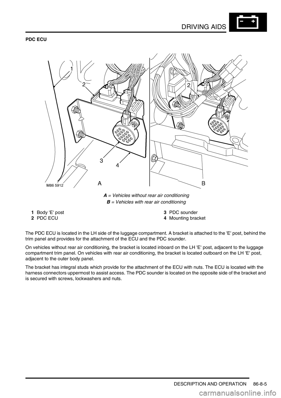
PDC ECU
A = Vehicles without rear air conditioning
B = Vehicles with rear air conditioning
1Body 'E' post
2PDC ECU3PDC sounder
4Mounting bracket
The PDC ECU is located in the LH side of the luggage compartment. A bracket is attached to the 'E' post, behind the
trim panel and provides for the attachment of the ECU and the PDC sounder.
On vehicles without rear air conditioning, the bracket is located inboard on the LH 'E' post, adjacent to the luggage
compartment trim panel. On vehicles with rear air conditioning, the bracket is located outboard on the LH 'E' post,
adjacent to the outer body panel.
The bracket has integral studs which provide for the attachment of the ECU with nuts. The ECU is located with the
harness connectors uppermost to assist access. The PDC sounder is located on the opposite side of the bracket and
is secured with screws, lockwashers and nuts.
Page 1445 of 1529
DRIVING AIDS
86-8-8 DESCRIPTION AND OPERATION
Sensors
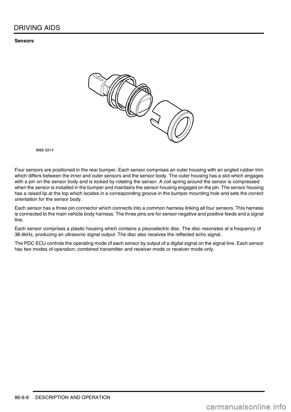
Four sensors are positioned in the rear bumper. Each sensor comprises an outer housing with an angled rubber trim
which differs between the inner and outer sensors and the sensor body. The outer housing has a slot which engages
with a pin on the sensor body and is locked by rotating the sensor. A coil spring around the sensor is compressed
when the sensor is installed in the bumper and maintains the sensor housing engaged on the pin. The sensor housing
has a raised lip at the top which locates in a corresponding groove in the bumper mounting hole and sets the correct
orientation for the sensor body.
Each sensor has a three pin connector which connects into a common harness linking all four sensors. This harness
is connected to the main vehicle body harness. The three pins are for sensor negative and positive feeds and a signal
line.
Each sensor comprises a plastic housing which contains a piezoelectric disc. The disc resonates at a frequency of
38.4kHz, producing an ultrasonic signal output. The disc also receives the reflected echo signal.
The PDC ECU controls the operating mode of each sensor by output of a digital signal on the signal line. Each sensor
has two modes of operation; combined transmitter and receiver mode or receiver mode only.
Page 1447 of 1529
DRIVING AIDS
86-8-10 DESCRIPTION AND OPERATION
Sounder
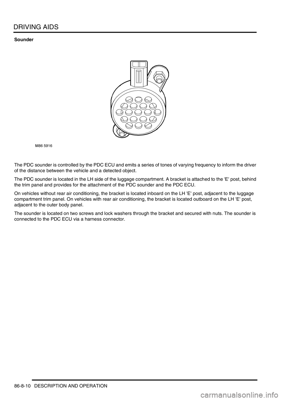
The PDC sounder is controlled by the PDC ECU and emits a series of tones of varying frequency to inform the driver
of the distance between the vehicle and a detected object.
The PDC sounder is located in the LH side of the luggage compartment. A bracket is attached to the 'E' post, behind
the trim panel and provides for the attachment of the PDC sounder and the PDC ECU.
On vehicles without rear air conditioning, the bracket is located inboard on the LH 'E' post, adjacent to the luggage
compartment trim panel. On vehicles with rear air conditioning, the bracket is located outboard on the LH 'E' post,
adjacent to the outer body panel.
The sounder is located on two screws and lock washers through the bracket and secured with nuts. The sounder is
connected to the PDC ECU via a harness connector.
Page 1456 of 1529
NAVIGATION SYSTEM
DESCRIPTION AND OPERATION 87-3
Navigation Computer
The navigation computer is installed in the DIN radio slot in the fascia. A spring loaded catch on each side of the
navigation computer secures it in position. Slide tools, installed in slots at the bottom front corners of the navigation
computer, are required to unlock the catches during removal.
The navigation computer contains all the hardware and software required for control of the navigation, radio and CD
systems, including the GPS receiver and a solid state piezo gyro for the navigation system. The piezo gyro measures
the motion of the vehicle around its vertical axis.
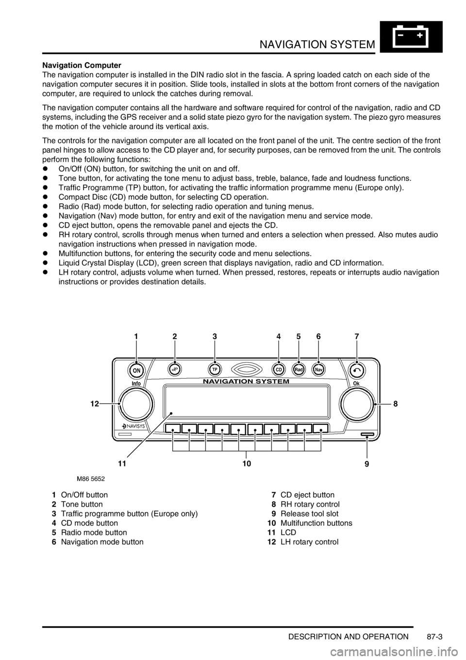
The controls for the navigation computer are all located on the front panel of the unit. The centre section of the front
panel hinges to allow access to the CD player and, for security purposes, can be removed from the unit. The controls
perform the following functions:
lOn/Off (ON) button, for switching the unit on and off.
lTone button, for activating the tone menu to adjust bass, treble, balance, fade and loudness functions.
lTraffic Programme (TP) button, for activating the traffic information programme menu (Europe only).
lCompact Disc (CD) mode button, for selecting CD operation.
lRadio (Rad) mode button, for selecting radio operation and tuning menus.
lNavigation (Nav) mode button, for entry and exit of the navigation menu and service mode.
lCD eject button, opens the removable panel and ejects the CD.
lRH rotary control, scrolls through menus when turned and enters a selection when pressed. Also mutes audio
navigation instructions when pressed in navigation mode.
lMultifunction buttons, for entering the security code and menu selections.
lLiquid Crystal Display (LCD), green screen that displays navigation, radio and CD information.
lLH rotary control, adjusts volume when turned. When pressed, restores, repeats or interrupts audio navigation
instructions or provides destination details.
1On/Off button
2Tone button
3Traffic programme button (Europe only)
4CD mode button
5Radio mode button
6Navigation mode button7CD eject button
8RH rotary control
9Release tool slot
10Multifunction buttons
11LCD
12LH rotary control
Page 1458 of 1529

NAVIGATION SYSTEM
DESCRIPTION AND OPERATION 87-5
System Settings Menu
The system settings menu provides access to features that can be changed to suit market and personal preferences
and to navigation system operating features. On European systems, the system settings menu also includes
computer games and a currency converter. While the navigation computer is in the navigation mode, the system
settings menu can be accessed by pressing the Nav button. Using the RH rotary control, the following features can
be selected and adjusted:
lTIME – Allows the navigation system clock to be set to local time as opposed to the Greenwich Mean Time (GMT)
transmitted from the GPS satellites. The local time setting is necessary for correct navigation on routes with time
restrictions and for Estimated Time of Arrival (ETA) calculations. The time can only be adjusted in 30 minute
steps.
lSAVE POSITION– Allows the current vehicle position to be saved and allocated a name in the navigation
destination memory.
lGAMES – Provides access to a selection of computer games.
lLANGUAGE– Allows the navigation system language and voice (where applicable) to be changed.
lANIMATIONS– Allows the LCD animations to be switched on and off.
lMEASURING UNIT – Allows the route guidance distances displayed on the LCD to be switched between metric
and Imperial units.
lANNOUNCEMENT ETA – Allows the route guidance ETA announcement to be switched on and off.
lCALCULATE EURO – Provides access to a currency converter.
User Menu
The user menu provides access to further features that can be changed to suit personal preferences. While the
navigation computer is in navigation, radio or CD modes, the user menu can be accessed by pressing and holding
the tone button for more than 2 seconds. The user menu is displayed over two screens, which can be toggled between
using the ⇒ multifunction button. Using the appropriate multifunction button or the RH rotary control, the following
settings can be selected and adjusted:
Screen 1
lGal – Automatic volume control setting (see above).
lTel – If a handsfree telephone system is connected to the navigation computer, allows either mute (telephone
mute mode) or audio signal (telephone conversation via the ICE speakers) to be selected.
lLcd – The LCD can be set to appear negative, positiveor automatic. In automatic, the display will be positive or
negative, depending on the setting of the exterior lamps.
lLed – A Light Emitting Diode (LED) in the display can be set to off or blinking. When set to blinking, the LED
flashes when the navigation computer is switched off.
lM/S – Radio reception can be set to Stereo, Mono or Auto, to suppress interference and reflections and so
optimise reception. Stereo is for exceptionally good reception conditions. Mono is for poor reception conditions.
In auto, the normal setting, the navigation computer automatically switches between stereo and mono depending
on reception conditions.
Screen 2
lNav – Sets how audio navigation instructions are delivered. In onl, other audio sources are suppressed and only
the navigation instruction is output to the speakers. In mixed, the volume of any other audio source is reduced
and the volume of the navigation announcement is the same as the original audio source +/– 6 dB (adjustable).
In independ, the audio source and navigation announcement can be set to independent volume levels.
lAux – Used to switch auxiliary CD AF connections between Aux mode on and Aux mode off. If no CD
autochanger is installed, an external cassette or CD player can be connected to the navigation computer and
powered by switching on the auxiliary CD AF connections.
lCmp – Allows a compass to be shown on the LCD when route guidance is not active.
lBeV – Used to adjust the signal tone volume. Signal tones sound to confirm storage confirmation etc. and can
be set between 0 (quiet) and +5 (loud).
Page 1461 of 1529
NAVIGATION SYSTEM
87-8 DESCRIPTION AND OPERATION
Calibration Routine
1Park the vehicle outside in an area clear of high buildings, trees etc.
NOTE: The more open the surrounding area is, the faster the system will acquire sufficient GPS satellite signals to
begin calibration. To minimise the calibration time, the vehicle should not be moved again until the calibration
ride.
2Turn the ignition switch to position II. If the navigation computer does not come on, press the navigation
computer ON button.
3If necessary, use the navigation computer multifunction buttons to enter the security code.
4Turn the ignition switch to position 0 and remove the ignition key.
5Press the navigation computer ON button.
6Call up the SENSORS screen on the LCD:
lIf the navigation CD-ROM has not been installed before, press and hold multifunction button 1 then press
multifunction button 10.
lIf the navigation CD-ROM has been installed before, use the garage menu as detailed above.
7Turn the LH rotary control to minimum volume.
8Wait for 30 minutes. If necessary, the vehicle can be left unattended and locked.
NOTE: Land Rover recommend a minimum of 30 minutes be allowed to elapse in order to ensure that only a short
distance need be driven to achieve calibration.
9After the 30 minutes have elapsed, ensure the navigation computer LCD shows a GPS almanac figure of 27 or
higher.
10Start the vehicle engine and allow to idle.
11Install the navigation CD-ROM.
12Wait until the navigation computer LCD prompts for a language to be selected. Turn the RH rotary control to
scroll through the options, highlight the required language and press the RH rotary control to select.
13The navigation computer LCD will prompt for a voice to be selected. Turn the RH rotary control to scroll through
the options, highlight the required voice and press the RH rotary control to select.
14Wait until the navigation computer LCD advises "language has been loaded OK". Press the RH rotary control to
confirm the language and voice selections.
15The navigation computer LCD will default to the CALIBRATION RIDE screen and should show the
CALIBRATION RIDE CAN START message. The GPS data and the road speed counter will also be shown.
16Drive the vehicle over a road route approximating that shown below (it is not necessary to copy the route
exactly). Calibration is complete when the navigation computer LCD switches to show DESTINATION & POI
and the satellite graphic. If all the pre calibration ride conditions were complied with, calibration is typically
achieved within 3 miles (5 km) and usually occurs when the vehicle returns to the start point. However,
calibration may be achieved earlier in the journey and, if it is, there is no need to complete the remainder of the
calibration route.
17After calibration is achieved, return to the dealership, park the vehicle and stop the engine.
18Turn the ignition switch to position I.
19Use the system settings menu to set the navigation computer to local time and the required units of measure:
aPress the Nav button.
bTurn the RH rotary control to scroll through the displayed menu, highlight TIME and press the RH rotary
control to select. Press the + or – multifunction button to adjust the time in 30 minute steps. Select the 24
hour clock and confirm by pressing the OK multifunction button.
cIf metric units of measure are required, go to step e) (the navigation computer defaults to metric units of
measure).
dIf Imperial units of measure are required, turn the RH rotary control to scroll through the displayed menu,
highlight MEASURING UNIT and press the RH rotary control to select. Turn the RH rotary control to
highlight IMPERIAL and press the RH rotary control to select.
ePress the Nav button to return to the destination menu.
20Calibration is complete. The navigation system is ready for use.
NOTE: The accuracy of the system will automatically be fine tuned when a further journey is made, but this is not
required as part of the calibration procedure.
NOTE: In European countries, the territory will have to be set the first time the navigation system is used, and the
first time a destination in another country is selected. The first time the navigation system is used or a destination
in another country is selected, a map is displayed with the default/current territory highlighted. To change the
territory: Press the RH rotary control to display the territory list; turn the RH rotary control to scroll through the
list and highlight the required territory; press the RH rotary control to confirm the selection.
Page 1475 of 1529
NAVIGATION SYSTEM
87-22 DESCRIPTION AND OPERATION
On-Board Monitor (Display Unit)
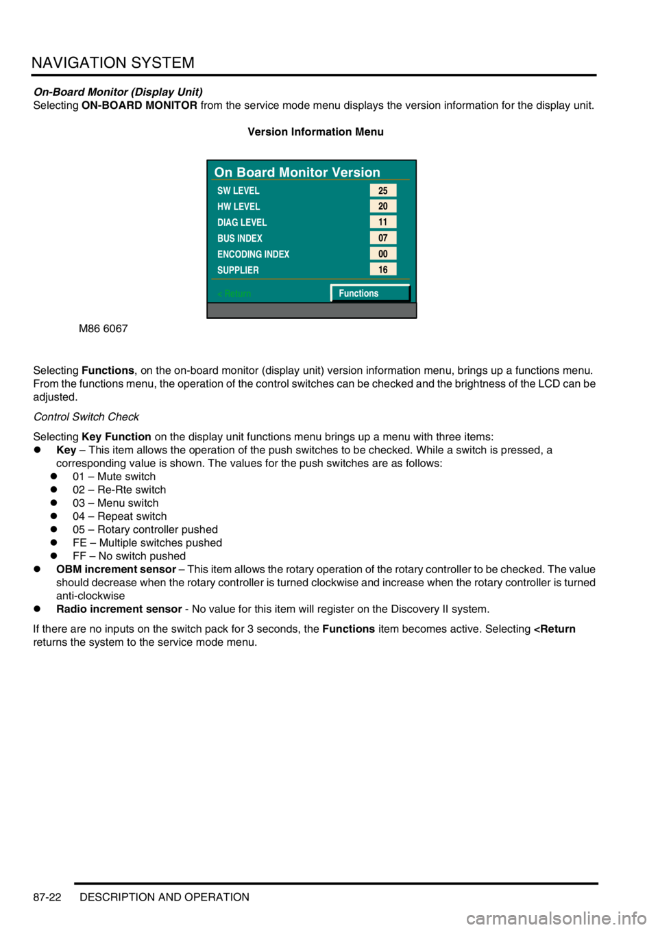
Selecting ON-BOARD MONITOR from the service mode menu displays the version information for the display unit.
Version Information Menu
Selecting Functions, on the on-board monitor (display unit) version information menu, brings up a functions menu.
From the functions menu, the operation of the control switches can be checked and the brightness of the LCD can be
adjusted.
Control Switch Check
Selecting Key Function on the display unit functions menu brings up a menu with three items:
lKey – This item allows the operation of the push switches to be checked. While a switch is pressed, a
corresponding value is shown. The values for the push switches are as follows:
l01 – Mute switch
l02 – Re-Rte switch
l03 – Menu switch
l04 – Repeat switch
l05 – Rotary controller pushed
lFE – Multiple switches pushed
lFF – No switch pushed
lOBM increment sensor – This item allows the rotary operation of the rotary controller to be checked. The value
should decrease when the rotary controller is turned clockwise and increase when the rotary controller is turned
anti-clockwise
lRadio increment sensor - No value for this item will register on the Discovery II system.
If there are no inputs on the switch pack for 3 seconds, the Functions item becomes active. Selecting
M86 6067
On Board Monitor Version
SW LEVEL
HW LEVEL
DIAG LEVEL
BUS INDEX
ENCODING INDEX
SUPPLIER
< Return25
20
11
07
00
16
Functions
Page 1479 of 1529
NAVIGATION SYSTEM
87-26 DESCRIPTION AND OPERATION
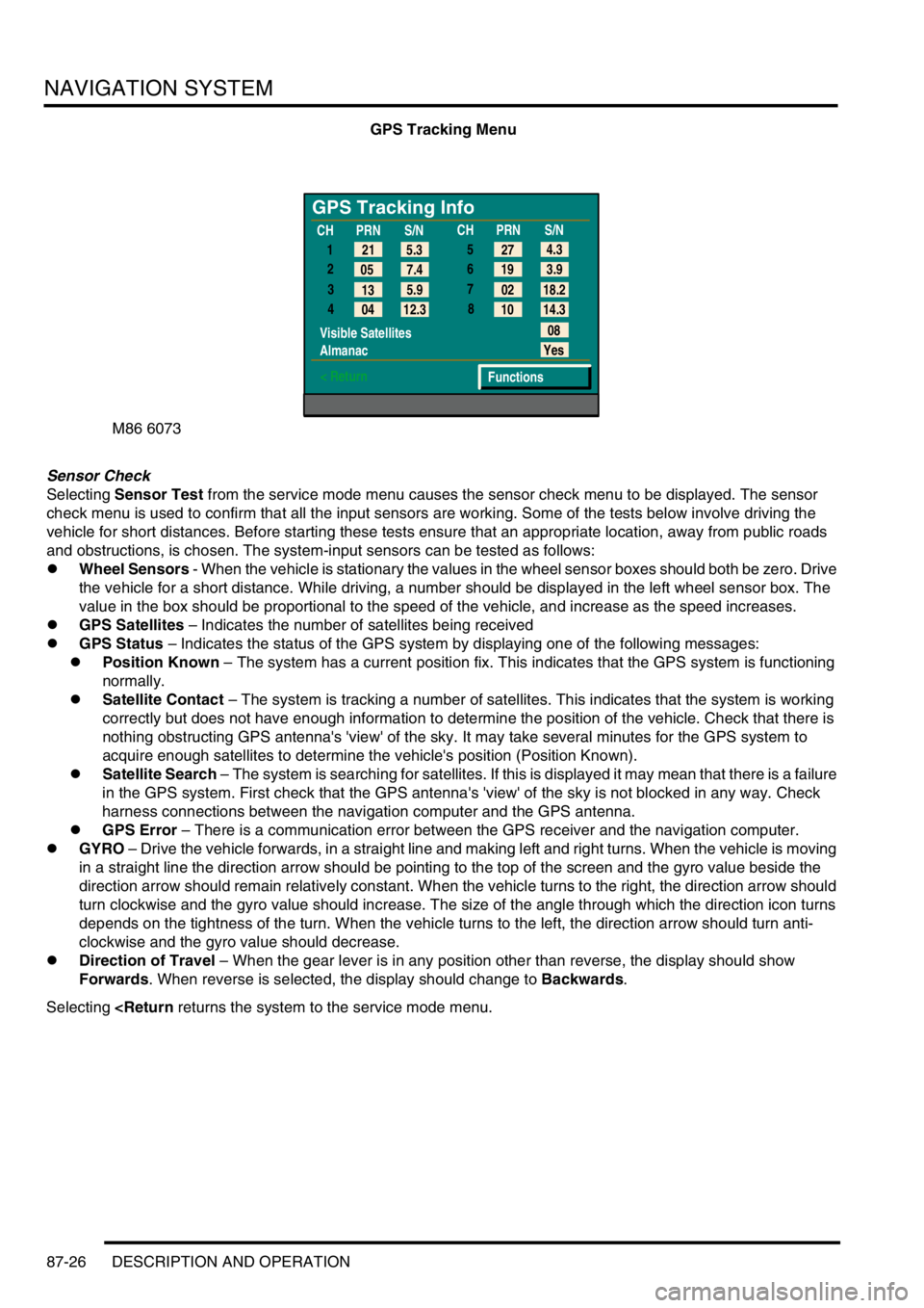
GPS Tracking Menu
Sensor Check
Selecting Sensor Test from the service mode menu causes the sensor check menu to be displayed. The sensor
check menu is used to confirm that all the input sensors are working. Some of the tests below involve driving the
vehicle for short distances. Before starting these tests ensure that an appropriate location, away from public roads
and obstructions, is chosen. The system-input sensors can be tested as follows:
lWheel Sensors - When the vehicle is stationary the values in the wheel sensor boxes should both be zero. Drive
the vehicle for a short distance. While driving, a number should be displayed in the left wheel sensor box. The
value in the box should be proportional to the speed of the vehicle, and increase as the speed increases.
lGPS Satellites – Indicates the number of satellites being received
lGPS Status – Indicates the status of the GPS system by displaying one of the following messages:
lPosition Known – The system has a current position fix. This indicates that the GPS system is functioning
normally.
lSatellite Contact – The system is tracking a number of satellites. This indicates that the system is working
correctly but does not have enough information to determine the position of the vehicle. Check that there is
nothing obstructing GPS antenna's 'view' of the sky. It may take several minutes for the GPS system to
acquire enough satellites to determine the vehicle's position (Position Known).
lSatellite Search – The system is searching for satellites. If this is displayed it may mean that there is a failure
in the GPS system. First check that the GPS antenna's 'view' of the sky is not blocked in any way. Check
harness connections between the navigation computer and the GPS antenna.
lGPS Error – There is a communication error between the GPS receiver and the navigation computer.
lGYRO – Drive the vehicle forwards, in a straight line and making left and right turns. When the vehicle is moving
in a straight line the direction arrow should be pointing to the top of the screen and the gyro value beside the
direction arrow should remain relatively constant. When the vehicle turns to the right, the direction arrow should
turn clockwise and the gyro value should increase. The size of the angle through which the direction icon turns
depends on the tightness of the turn. When the vehicle turns to the left, the direction arrow should turn anti-
clockwise and the gyro value should decrease.
lDirection of Travel – When the gear lever is in any position other than reverse, the display should show
Forwards. When reverse is selected, the display should change to Backwards.
Selecting
GPS Tracking Info
1
2
3
4
Visible Satellites
Almanac
< Return
08
Yes
Functions 5.3 21
7.4 05
5.9
13
12.3
04CHPRN
S/N
CHPRN
S/N
4.3
27
3.9 19
18.2 02
14.3 10 5
6
7
8