1999 LAND ROVER DISCOVERY lock
[x] Cancel search: lockPage 1346 of 1529

ALARM SYSTEM AND HORN
DESCRIPTION AND OPERATION 86-4-23
In order for speed related locking to activate the following conditions must be met:
lAll doors unlocked.
lEngine running.
lVehicle speed greater than 4 mph (7 km/h).
Acclimatisation related locking
Acclimatisation related locking allows the engine to be started and then the vehicle locked with a spare key and left
unattended to allow the vehicle interior to reach the desired temperature.
There are two configurations for acclimatisation related locking:
lAcclimatisation related locking not active.
lAcclimatisation related locking active.
Once the engine is started, the vehicle is locked with a spare key at the driver's door while the engine is running.
During these conditions the alarm is not armed.
In order to activate acclimatisation related locking the following conditions must be met:
lEngine running.
lAll doors closed.
Visual warnings
The direction indicators serve as a visual indication when the alarm is triggered. The direction indicators are also used
as a visual indication during lock/unlock procedures.
There are three configurations of alarm armed/disarmed indication:
lNo direction indicators on, alarm armed/disarmed/trigger.
lDirection indicators on, alarm trigger only.
lDirection indicators on, alarm armed/disarmed/trigger.
Dependent on system configuration the direction indicators flash one short pulse to confirm that the alarm is armed
and flash two short pulses to confirm that the vehicle is super locked. If the alarm is triggered the direction indicators
operate in phase with the audible warning. When the alarm is disarmed, the direction indicators flash one long pulse.
Audible warning
An audible warning device is used to indicate that the alarm has been triggered, or a mislock has occurred, or an EKA
request has occurred, or the EKA code has been entered.
There are six audible warning configurations:
lNo sound (audible warnings disabled).
lAlarm sounder only.
lVehicle horn only.
lAlarm sounder and vehicle horn.
lBBUS only.
lAlarm sounder, vehicle horn and BBUS.
Depending on which market the vehicle is sold, either the vehicle horn, a specific alarm sounder, or a BBUS operates
in phase with the direction indicators when the alarm is triggered. The audible warning device operates for
approximately 30 seconds at 0.25 second on, and 0.25 second off. The BCU allows the alarm to be triggered up to 3
times in any armed period.
Theft deterrent LED
An LED located in the instrument pack indicates the status of the alarm system.
There are eight theft deterrent alarm configurations:
lNo handset low battery warning.
lHandset low battery warning.
lNo passive immobilisation.
lPassive immobilisation.
lEngine immobilised (ignition off, LED off).
lEngine immobilised (ignition off, LED flashes).
lNo alarm tampered indication.
lAlarm tampered indication.
Page 1347 of 1529

ALARM SYSTEM AND HORN
86-4-24 DESCRIPTION AND OPERATION
The theft deterrent LED utilises a particular flash to show the status of the following:
lAlarm armed.
lEngine immobilised.
lAlarm tampered.
lHandset low battery warning.
Transit mode
To prevent excessive battery drain during transportation to overseas markets, the vehicle is placed in a transit mode
at the end of line test.
The following functions are disabled when the vehicle is in transit mode:
lVolumetric sensors.
lPassive immobilisation.
lMobilisation of the vehicle by use of door lock.
lIgnition key interlock.
lElectric seat enable time-out with drivers door open.
To exit this mode, switch on the ignition and simultaneously hold down the heated rear window and the rear fog lamp
switch for 2 seconds.
Transit mode can be entered using Testbook.
Page 1348 of 1529
ALARM SYSTEM AND HORN
REPAIR 86-4-25
REPAIR
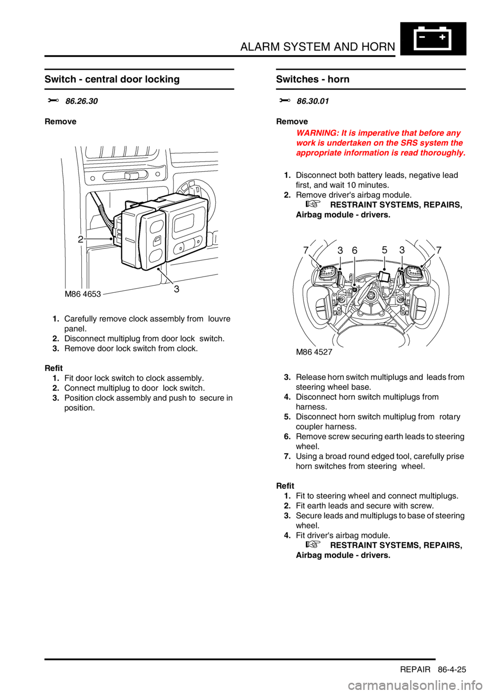
Switch - central door locking
$% 86.26.30
Remove
1.Carefully remove clock assembly from louvre
panel.
2.Disconnect multiplug from door lock switch.
3.Remove door lock switch from clock.
Refit
1.Fit door lock switch to clock assembly.
2.Connect multiplug to door lock switch.
3.Position clock assembly and push to secure in
position.
Switches - horn
$% 86.30.01
Remove
WARNING: It is imperative that before any
work is undertaken on the SRS system the
appropriate information is read thoroughly.
1.Disconnect both battery leads, negative lead
first, and wait 10 minutes.
2.Remove driver's airbag module.
+ RESTRAINT SYSTEMS, REPAIRS,
Airbag module - drivers.
3.Release horn switch multiplugs and leads from
steering wheel base.
4.Disconnect horn switch multiplugs from
harness.
5.Disconnect horn switch multiplug from rotary
coupler harness.
6.Remove screw securing earth leads to steering
wheel.
7.Using a broad round edged tool, carefully prise
horn switches from steering wheel.
Refit
1.Fit to steering wheel and connect multiplugs.
2.Fit earth leads and secure with screw.
3.Secure leads and multiplugs to base of steering
wheel.
4.Fit driver's airbag module.
+ RESTRAINT SYSTEMS, REPAIRS,
Airbag module - drivers.
Page 1352 of 1529
ALARM SYSTEM AND HORN
REPAIR 86-4-29
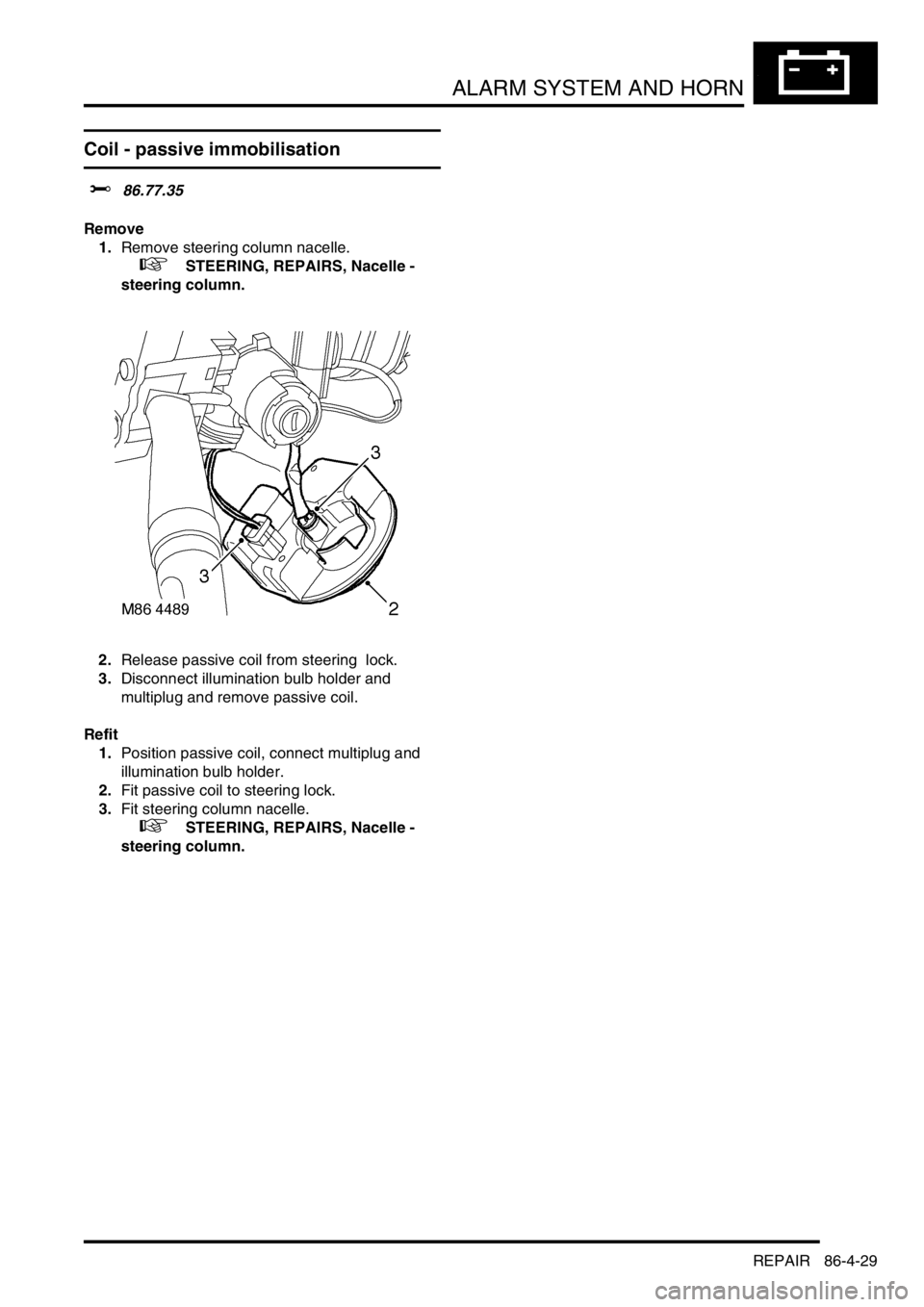
Coil - passive immobilisation
$% 86.77.35
Remove
1.Remove steering column nacelle.
+ STEERING, REPAIRS, Nacelle -
steering column.
2.Release passive coil from steering lock.
3.Disconnect illumination bulb holder and
multiplug and remove passive coil.
Refit
1.Position passive coil, connect multiplug and
illumination bulb holder.
2.Fit passive coil to steering lock.
3.Fit steering column nacelle.
+ STEERING, REPAIRS, Nacelle -
steering column.
Page 1354 of 1529
WINDOWS
DESCRIPTION AND OPERATION 86-5-1
WINDOWS DESCRIPTION AND OPERAT ION
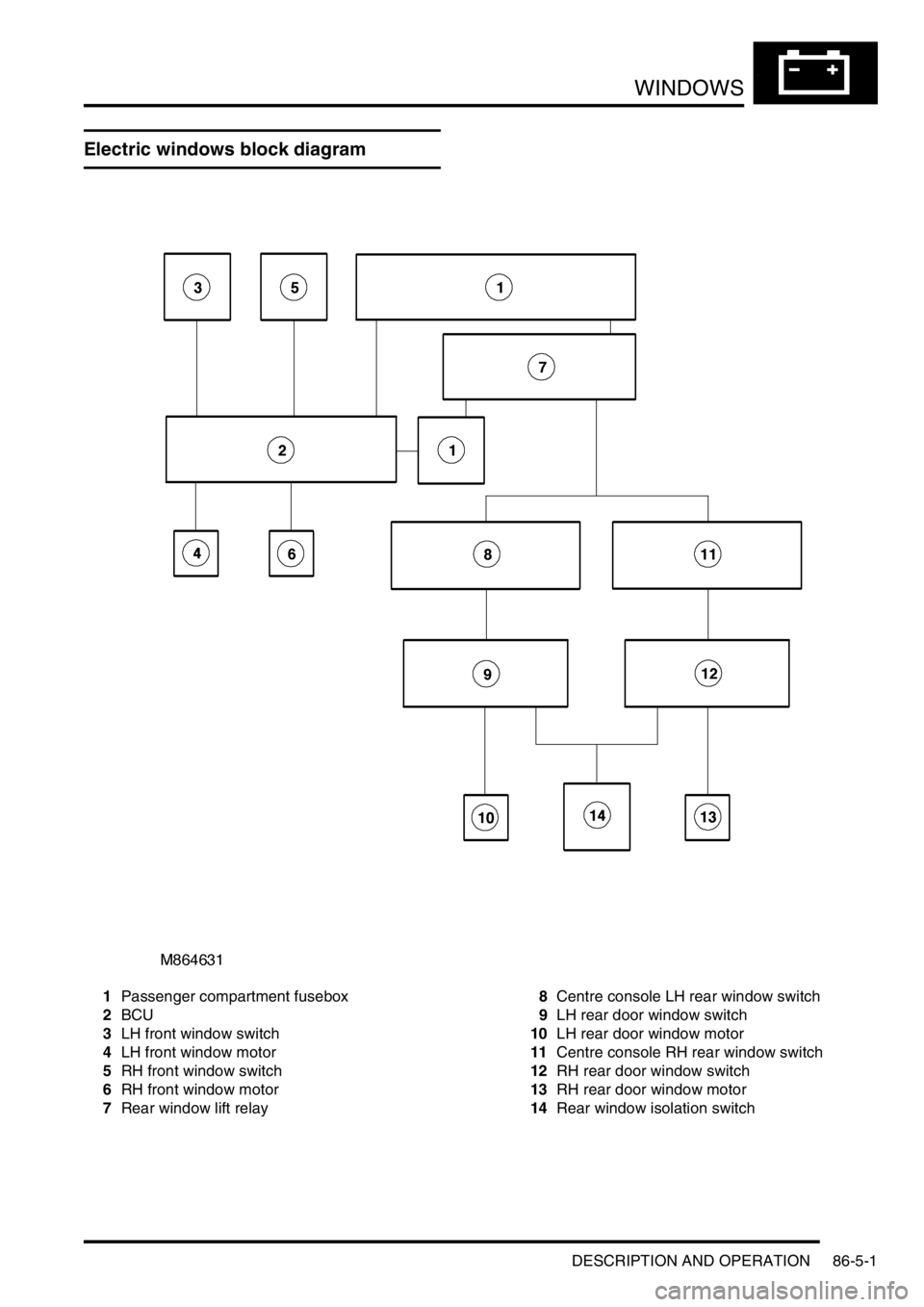
Electric windows block diagram
1Passenger compartment fusebox
2BCU
3LH front window switch
4LH front window motor
5RH front window switch
6RH front window motor
7Rear window lift relay8Centre console LH rear window switch
9LH rear door window switch
10LH rear door window motor
11Centre console RH rear window switch
12RH rear door window switch
13RH rear door window motor
14Rear window isolation switch
Page 1394 of 1529
IN CAR ENTERTAINMENT
DESCRIPTION AND OPERATION 86-6-27
Operation
DVD Player Functionality
The following defines the functionality of the unit. Further details of system operation can found in the DVD System
Owner's Manual, Publication Part No. LRL0482, supplied with the system.
DVD Region Selection
The DVD player is capable of playing discs from any region. The DVD can only be set to play discs of one region at
a time. A code is entered using the remote control handset to set the unit to the required region. The unit is set to the
correct region on production and therefore this will not be required by either the dealer or the customer.
If the unit region is required to be changed for any reason, Land Rover Special Vehicles must be contacted for the
required code and procedure.
NOTE: The unit can be re-configured for region up to five times. After the fifth attempt to re-configure the region, the
unit will be locked in the fifth region that was programmed. This will require the unit to be returned to the manufacturer
to be reset. The manufacturer will charge a fee for this service.
DVD Player CD Audio Function
The DVD player can play audio CD's through the vehicle audio system. This allows the user to play additional CD's
without having to remove the CD autochanger cartridge.
The overhead console LCD monitor must be open to play audio CD's.. Normal audio CD functionality such as repeat,
random and track select etc. can be accessed using the remote control handset.
The DVD player in the overhead console will also function independently of the vehicle audio system, and operate as
an additional CD player. The rear seat passengers can listen to audio CD's via the three headphone sockets on the
overhead console and via the two radio/headphone amplifier units (if fitted), while the front seat passengers
simultaneously listen to CD's played on the vehicle audio system and CD autochanger.
DVD/CD Output using the Vehicle Audio System
To play the DVD/CD audio output from the overhead console through the vehicle audio speakers, the speaker button
on the overhead console or remote control handset must be pressed. 'Speaker On' appears on the LCD monitor and
the head unit CD functionality is suspended. The audio output from the overhead console will now be played from the
vehicle speaker system. The head unit volume control, tone control, Navigation announcements and mobile phone (if
fitted) will function as normal and override the DVD output. A second press of the speaker button will switch the audio
output back to the head unit. 'Speaker Off' will be displayed on the LCD monitor.
The overhead console will remember the selected speaker condition if the overhead console is switched off by closing
the monitor, the console switched off using the handset or accessory power removed from the overhead console.
Power Up Conditions
On application of accessory power, the overhead console will perform the following:
lIf no disc is in the DVD player, the LCD monitor will display a blue screen and enter 'AUX' input mode.
When a DVD or CD is inserted in the DVD player, the system will change to DVD input mode. The disc will
attempt to play but may be limited by the disc media. Some discs will play automatically, some will display a menu
and others require the user to start playback.
lIf a disc was in the DVD player and the system was in 'Play', 'Pause', 'FF' or 'Rew' when powered down, playback
will start when power is re-applied.
lIf a disc was in the DVD player and the system was in 'Stop' when powered down, the system will enter DVD
mode and a blue screen will be displayed on the LCD monitor.
lSpeaker selection will remain in the same state as when the accessory power was removed.
Engine Cranking
If the unit is playing a DVD or CD when the ignition switch is moved to position III (engine crank), the system will stop
playing while the engine is cranking. Playback will resume at the point the playback was stopped when the ignition
switch is returned to position I or II.
Page 1401 of 1529
IN CAR ENTERTAINMENT
86-6-34 REPAIRS
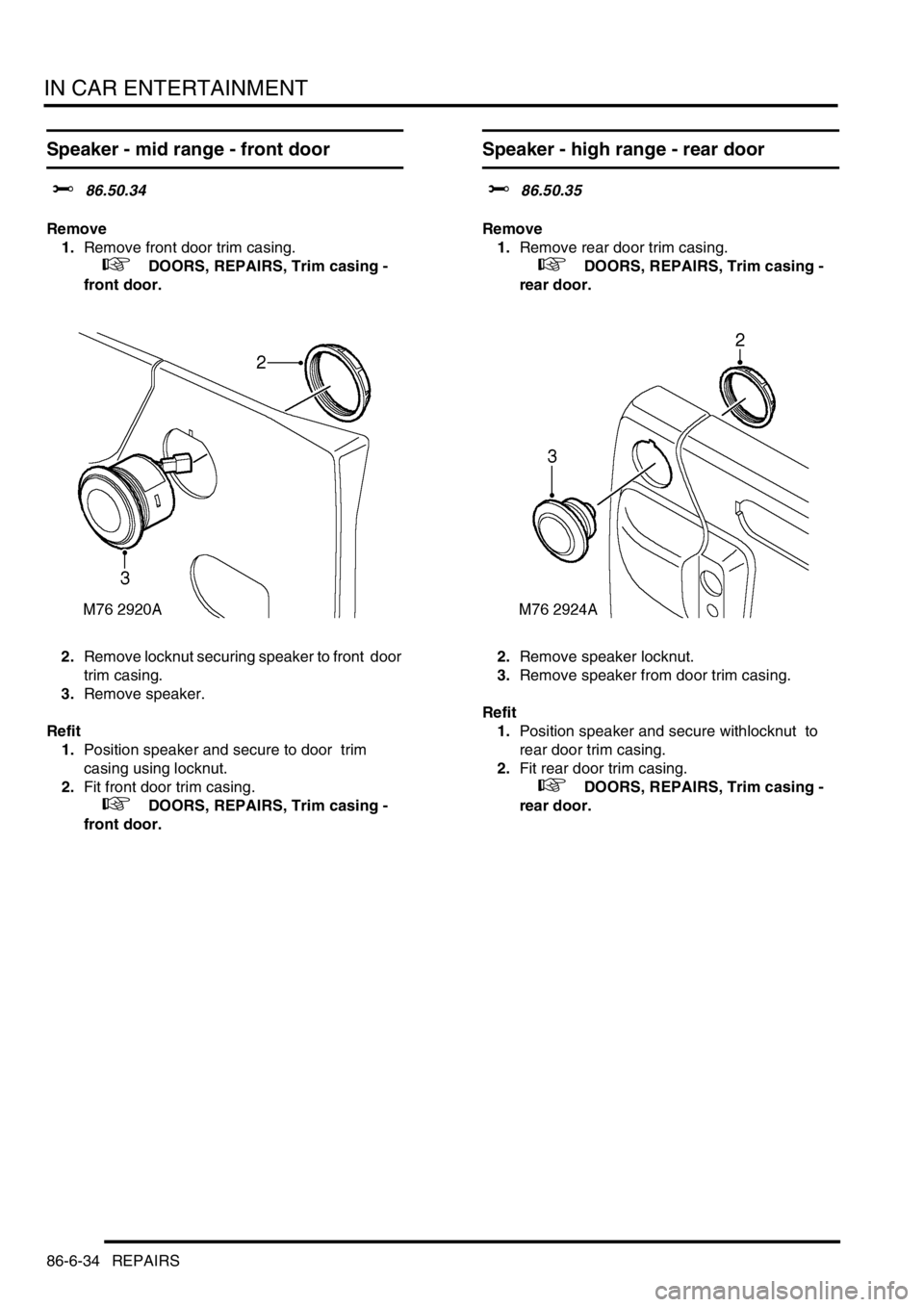
Speaker - mid range - front door
$% 86.50.34
Remove
1.Remove front door trim casing.
+ DOORS, REPAIRS, Trim casing -
front door.
2.Remove locknut securing speaker to front door
trim casing.
3.Remove speaker.
Refit
1.Position speaker and secure to door trim
casing using locknut.
2.Fit front door trim casing.
+ DOORS, REPAIRS, Trim casing -
front door.
Speaker - high range - rear door
$% 86.50.35
Remove
1.Remove rear door trim casing.
+ DOORS, REPAIRS, Trim casing -
rear door.
2.Remove speaker locknut.
3.Remove speaker from door trim casing.
Refit
1.Position speaker and secure withlocknut to
rear door trim casing.
2.Fit rear door trim casing.
+ DOORS, REPAIRS, Trim casing -
rear door.
Page 1412 of 1529

HARNESSES
REPAIRS 86-7-7
Refit
1.With assistance, position harness to air
conditioning ducting and secure with cable ties.
2.Secure harness to sunroof harness with cable
clips.
3.Connect multiplug to RF receiver.
4.Feed harness to LH and RH upper 'E' posts.
5.Feed harness through 'E' post to tail lamp and
rear bumper and secure with grommet.
6.Connect multiplug to fuel flap solenoid and
alarm sounder.
7.Position alarm sounder to rear quarter and
secure with nut to 9 Nm (7 lbf.ft).
8.Position both RH earth header to 'E' post and
tighten nut to 10 Nm (7 lbf.ft).
9.Feed tail door harness through 'E' post and
secure with grommet.
10.Position harness sleeve to outer edge of door
and pull harness through door.
11.Secure harness to tail door with clips.
12.Connect washer tube to rear of wiper arm.
13.Remove tape from draw string and secure to
CHMSL harness.
14.Draw harness through tail door and connect
Lucars to CHMSL.
15.Fit CHMSL cover and secure with screws.
16.Connect multiplug to door lock switch.
17.Connect Lucars to HRW.
18.Connect multiplug to rear wiper motor.
19.Connect multiplug to door latch.
20.Fit plastic sheet to tail door, ensuring it aligns
with witness marks.
21.Fit tail door trim casing.
+ DOORS, REPAIRS, Trim casing - tail
door.
22.Connect Lucar to radio aerial RH amplifier.
23.Secure harness to RH side of body with clips
and retainers.
24.Position both LH earth header to 'E' post and
tighten nut to 10 Nm (7 lbf.ft).
25.Connect multiplugs to both tail/flasher lamps
and secure harness to bumper with clips.
26.Fit both rear tail lamps.
+ LIGHTING, REPAIRS, Lamp - tail.
27.Secure harness to rear LH side of body with 6
cable clips.
28.Connect 2 Lucars to rear air conditioning unit.
29.Fit both luggage compartment trim casings.
+ INTERIOR TRIM COMPONENTS,
REPAIRS, Trim casing - side - loadspace.
30.Feed harness into position for rear interior light.
31.Connect Lucar to radio aerial LH amplifier.
32.Secure harness to body with cable ties clips
and retainers.
33.Secure air conditioning ducting to body with
rivets.
34.Feed harness to LH lower 'A' post. 35.Secure harness to LH side of body with cable
tie clips and retainers.
36.Connect and secure multiplugs to lower LH 'A'
post.
37.Feed harness through roof to centre.
38.Secure harness behind bonnet release cable.
39.Connect rear washer pipe at lower 'A' post and
secure with clip.
40.Secure harness to roof with clips.
41.Connect multiplug to interior mirror, ARC
accelerometer.
42.Position sound deadening panels and secure
with clips.
43.Fit headlining.
+ INTERIOR TRIM COMPONENTS,
REPAIRS, Headlining.
44.Fit fascia panel.
+ INTERIOR TRIM COMPONENTS,
REPAIRS, Fascia.