Page 1260 of 1529
WIPERS AND WASHERS
REPAIRS 84-25
Motor and linkage - wiper - windscreen
$% 84.15.11
Remove
1.Remove plenum air intake.
+ HEATING AND VENTILATION,
REPAIRS, Plenum Air Intake.
2.Remove 4 nuts and one bolt securing motor
mounting plate to body.
3.Remove nut and bolt securing linkage to body.
4.Release motor and linkage from body and
disconnect multiplug from windscreen wiper
motor.
5.Remove motor and linkage. 6.Remove nut securing linkage connecting rod to
wiper motor spindle.
7.Release link from motor spindle.
8.Remove 3 bolts securing motor to mounting
plate and remove motor.
Refit
1.Fit new wiper motor to mounting plate and
secure with bolts.
2.Connect link to motor spindle and tighten nut to
7 Nm (5.2 lbf.ft).
3.Fit motor and linkage to body, connect
multiplug. Tighten all fixings to 2.5 Nm (1.8
lbf.ft).
4.Fit plenum air intake.
+ HEATING AND VENTILATION,
REPAIRS, Plenum Air Intake.
Page 1261 of 1529
WIPERS AND WASHERS
84-26 REPAIRS
Switch - wiper and washer - windscreen
$% 84.15.34
WARNING: It is imperative that before any work
is undertaken on the SRS system the appropriate
information is read thoroughly.
Remove
1.Remove rotary coupler.
+ RESTRAINT SYSTEMS, REPAIRS,
Rotary coupler.
2.Release passive coil from steering column lock
and lower the coil without disconnecting the
harness.
3.Release front wiper delay multiplug from
column switch mounting bracket and
disconnect from harness.
4.Disconnect harness multiplug from wiper
switch.
5.Remove 2 screws securing switch, carefully
raise edge of switch bracket to clear location
peg and remove switch. Refit
1.Fit new switch to bracket and secure with
screws.
2.Connect harness multiplug to switch.
3.Connect front wiper delay multiplug and fit
multiplug to switch bracket.
4.Fit passive coil to column lock.
5.Fit rotary coupler.
+ RESTRAINT SYSTEMS, REPAIRS,
Rotary coupler.
Page 1262 of 1529
WIPERS AND WASHERS
REPAIRS 84-27
Jet - washer - headlamp
$% 84.20.08
The procedure to remove the headlamp washer jet
on 03MY vehicles is detailed in the front bumper
finisher job.
+ EXTERIOR FITTINGS, REPAIRS, Trim
finisher - bumper - front - from 03MY.
Remove
1.Remove retaining screw cover from jet
housing.
2.Remove screw securing jet to bumper.
3.Release jet and withdraw sufficiently to gain
access to washer tube. Disconnect tube from
jet and remove jet.
Refit
1.Connect jet to washer tube, ensuring it is
pushed fully home.
2.Locate jet in bumper, retain with screw and fit
screw cover.
Jet - washer - rear screen
$% 84.30.09
Remove
1.Remove spare wheel.
2.Remove rear screen wiper blade.
3.Release washer jet and washer jet tube from
wiper arm.
4.Release washer jet from washer jet tube and
remove jet.
Refit
1.Fit new washer jet to washer jet tube and fit to
wiper arm.
2.Fit rear screen wiper blade.
3.Fit spare wheel.
Page 1263 of 1529
WIPERS AND WASHERS
84-28 REPAIRS
Switch - rear wash
$% 84.30.27
Remove
1.Carefully remove switch from instrument cowl.
2.Disconnect multiplug and remove switch. Refit
1.Position new switch and connect multiplug.
2.Carefully push switch into instrument cowl.
Page 1264 of 1529
WIPERS AND WASHERS
REPAIRS 84-29
Motor - wiper - rear screen
$% 84.35.12
Remove
1.Remove spare wheel from taildoor.
2.Remove tail door trim casing.
+ DOORS, REPAIRS, Trim casing - tail
door.
3.Remove tail door water shedder.
4.Disconnect washer tube
5.Raise nut cover, remove nut and release wiper
arm.
6.Remove spindle nut and flat washer and
discard rubber seal.
7.Disconnect taildoor harness multiplug from
wiper motor.
8.Remove 2 bolts securing wiper motor to tail
door.
9.Remove wiper motor. Refit
1.Position wiper motor to door and secure with
bolts.
2.Connect tail door harness multiplug to wiper
motor.
3.Fit rubber seal, flat washer and spindle nut.
Tighten spindle nut to 3 Nm (2.2 lbf.ft).
4.Position wiper arm to tail door and connect
washer tube.
5.Tighten wiper arm nut to 20 Nm (15 lbf.ft) and
fit nut cover.
6.Fit tail door water shedder.
7.Fit tail door trim casing.
+ DOORS, REPAIRS, Trim casing - tail
door.
8.Fit spare wheel to tail door.
Page 1265 of 1529
WIPERS AND WASHERS
84-30 REPAIRS
Switch - wiper - rear - up to 03MY
$% 84.35.33
Remove
1.Carefully remove switch from instrument cowl.
2.Disconnect multiplug and remove switch.
Refit
1.Position new switch and connect multiplug.
2.Carefully push switch into instrument cowl.
Switch - wiper - rear - from 03MY
$% 843533
Remove
1.Remove 2 screws securing instrument cowl to
fascia and release the cowl from the retaining
clips.
2.Disconnect multiplug from the rear wiper
switch.
3.Remove the rear wiper switch from the
instrument cowl.
Refit
1.Fit and secure the rear wiper switch to the
instrument cowl and connect the multiplug.
2.Fit the instrument cowl to the fascia and secure
with screws.
Page 1288 of 1529

BODY CONTROL UNIT
DESCRIPTION AND OPERATION 86-3-1
BODY CONTROL UNIT DESCRIPTION AND OPERAT ION
Description
General
The Body Control Unit (BCU) is located behind the passenger glovebox and is connected to the main harness by four
connectors on its bottom edge and an additional connector located on the side of the BCU casing. Mounting the BCU
behind the fascia makes it reasonably inaccessible for intruders to disable the anti-theft system.
The BCU uses solid-state microprocessor control to perform logical operations and timing functions for a variety of
the vehicle's electrically operated systems, these include:
lDoor locking.
lAnti-theft alarm and immobilisation system.
lExterior lighting including direction indicators and hazard warning lamps.
lCourtesy lighting.
lWipers and washers.
lElectric windows and sunroof.
lHeated windows.
The BCU also communicates with several other electronically controlled systems such as the EAT ECU and SLABS
ECU and also has a datalink between the Intelligent Driver Module (IDM) and the instrument pack. The datalink is a
low speed bus capable of transmitting and receiving messages at a data rate of 10,400 bits per second. Additional
inputs and outputs to peripheral devices are included which are necessary for determining vehicle status for particular
logical operations e.g. crank, ignition key inserted, fuel flap enable etc.
The BCU receives its power supply from the engine compartment fuse box, and is protected by a 10 A fuse.
The BCU communicates with the IDM to provide the control signals to perform power switching operations in
conjunction with dedicated relays.
IDM
The IDM is integrated into the passenger compartment fuse box, which is mounted behind the fascia below the
steering column. There are no harnesses between the fuse box and the IDM. The IDM performs the power switching
operations for several of the vehicle's electrical systems.
The IDM communicates with the BCU and the instrument pack via a serial interface. If the BCU or the IDM is replaced,
the communications link between the two units has to be re-established. This can be done either by switching on the
ignition and leaving it on for five minutes, or by using TestBook. The vehicle immobilisation will remain active until the
communications link between the BCU and IDM has been re-established.
Transit mode
To prevent excessive battery drain during transit to overseas markets, the vehicle is placed in a transit mode. The
following functions are disabled when the vehicle is in transit mode:
lVolumetric sensors.
lPassive immobilisation.
lImmobilisation of the vehicle by use of door lock.
lIgnition key interlock.
lElectric seat enable time-out with driver's door open.
Page 1295 of 1529

BODY CONTROL UNIT
86-3-8 DESCRIPTION AND OPERATION
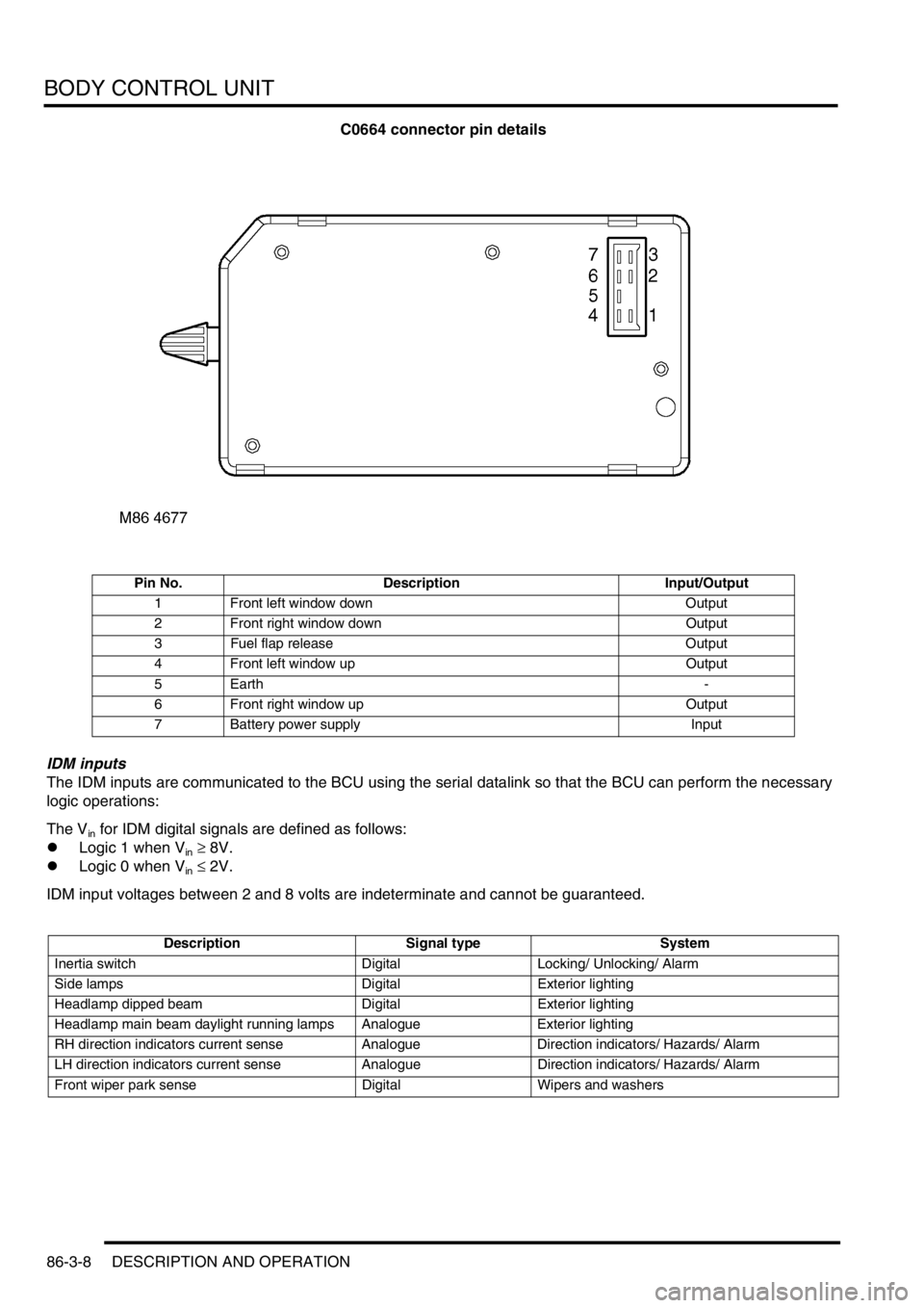
C0664 connector pin details
IDM inputs
The IDM inputs are communicated to the BCU using the serial datalink so that the BCU can perform the necessary
logic operations:
The V
in for IDM digital signals are defined as follows:
lLogic 1 when V
in ≥ 8V.
lLogic 0 when V
in ≤ 2V.
IDM input voltages between 2 and 8 volts are indeterminate and cannot be guaranteed.
Pin No. Description Input/Output
1 Front left window down Output
2 Front right window down Output
3 Fuel flap release Output
4 Front left window up Output
5Earth -
6 Front right window up Output
7 Battery power supply Input
Description Signal type System
Inertia switch Digital Locking/ Unlocking/ Alarm
Side lamps Digital Exterior lighting
Headlamp dipped beam Digital Exterior lighting
Headlamp main beam daylight running lamps Analogue Exterior lighting
RH direction indicators current sense Analogue Direction indicators/ Hazards/ Alarm
LH direction indicators current sense Analogue Direction indicators/ Hazards/ Alarm
Front wiper park sense Digital Wipers and washers