Page 172 of 1529

ENGINE - V8
REPAIRS 12-2-17
6. RH drive models: Remove brake servo heat
shield.
+ MANIFOLDS AND EXHAUST
SYSTEMS - V8, REPAIRS, Heat shield -
brake servo - Without Secondary Air
Injection.
7.Remove 8 bolts securing exhaust manifold to
cylinder head, release manifold and collect 2
gaskets.
8.Progressively remove 4 bolts securing the
rocker shaft and remove rocker shaft.
9.Remove push rods. Store push rods in their
fitted order. 10. Models with SAI: Using a 9 mm hexagonal
drive bit, remove 2 air injection adapters from
cylinder head; discard adapters.
Note: To release the adapter thread locking
agent and prevent damage to the cylinder
head, remove the adapters by alternately
loosening then tightening slightly. Repeat this
procedure until adapters are removed.
CAUTION: Do not use air tools to remove
adapters.
11.In the sequence shown, remove 10 bolts
securing the cylinder head to block. Discard the
bolts.
12.Remove cylinder head.
CAUTION: Support both ends of cylinder
head on blocks of wood.
Page 173 of 1529

ENGINE - V8
12-2-18 REPAIRS
13.Remove cylinder head gasket.
Refit
1.Clean mating faces of cylinder block and head
using suitable gasket removal spray and a
plastic scraper, ensure that bolt holes in block
are clean and dry. Clean mating faces of
cylinder head and exhaust manifold.
CAUTION: Do not use a metal scraper or
machined surfaces may be damaged.
2.Check head and block faces for warping and
pitting. If out of specification, renew head.
3. Models with SAI: Using a 5/8 in x 20 TPI
(threads per inch) UNF tap having a class 2A
thread, remove deposits from secondary air
injection adapter tappings in cylinder head.
CAUTION: Ensure that tap used has 20 TPI.
4.Fit cylinder head gasket with the word 'TOP'
uppermost.
CAUTION: Gasket must be fitted dry.
5.Carefully fit cylinder head and locate on
dowels.
6.Lightly lubricate new cylinder head bolt threads
with clean engine oil. 7.Noting that bolts 1, 3 and 5 are longer than the
remainder, fit bolts and tighten in the sequence
shown to 20 Nm (15 lbf.ft) then 90°, and finally
a further 90°.
CAUTION: Do not tighten bolts 180° in one
operation.
8. Models with SAI: Fit new air injection adapters
and using a 9 mm hexagonal drive bit, tighten
to 33 Nm (24 lbf.ft).
CAUTION: Do not use an air tool to tighten
adapters.
9.Clean push rods.
10.Lubricate ends of push rods with clean engine
oil.
11.Fit push rods in their removed order.
12.Clean bases of rocker pillars and mating faces
on cylinder head.
13.Clean contact surfaces on rockers, valves and
push rods.
14.Lubricate contact surfaces and rocker shaft
with clean engine oil.
15.Fit rocker shaft assembly and engage push
rods.
16.Fit rocker shaft bolts and progressively tighten
to 40 Nm (30 lbf.ft).
17.Position alternator mounting bracket, fit bolts
and tighten to 40 Nm (30 lbf.ft).
18.Position auxiliary drive belt tensioner, fit bolt
and tighten to 45 Nm (33 lbf.ft).
19.Connect ht leads to spark plugs in their fitted
order.
20. Using new gaskets, fit exhaust manifold to
cylinder head. Fit bolts and using sequence
shown, tighten initially to 15 Nm (11 lbf.ft), then
finally tighten to 36 Nm (28 lbf.ft).
21. RH drive models: Fit brake servo heat shield.
+ MANIFOLDS AND EXHAUST
SYSTEMS - V8, REPAIRS, Heat shield -
brake servo - Without Secondary Air
Injection.
22.Position engine earth lead, fit bolt and tighten to
22 Nm (16 lbf.ft).
23.Fit inlet manifold gasket.
+ MANIFOLDS AND EXHAUST
SYSTEMS - V8, REPAIRS, Gasket - inlet
manifold - lower.
Page 343 of 1529

ENGINE MANAGEMENT SYSTEM - V8
18-2-44 DESCRIPTION AND OPERATION
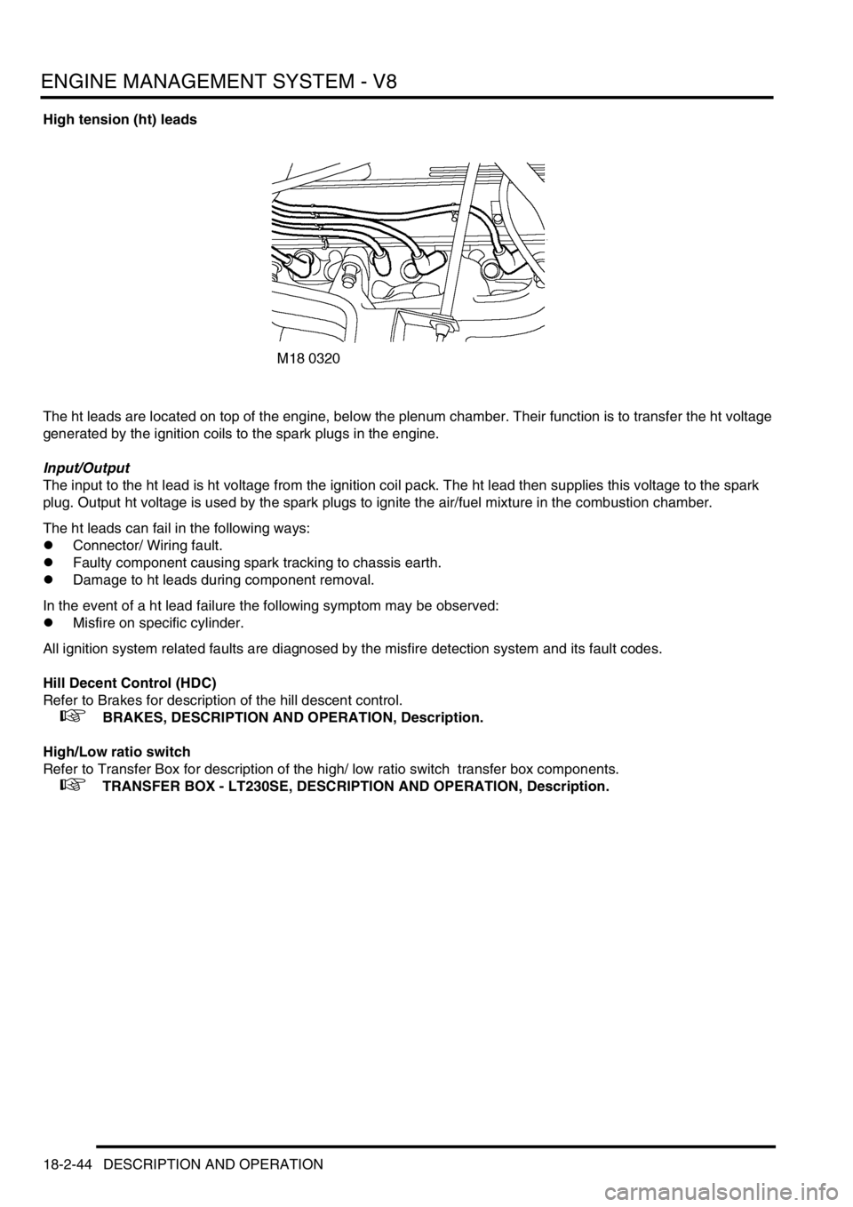
High tension (ht) leads
The ht leads are located on top of the engine, below the plenum chamber. Their function is to transfer the ht voltage
generated by the ignition coils to the spark plugs in the engine.
Input/Output
The input to the ht lead is ht voltage from the ignition coil pack. The ht lead then supplies this voltage to the spark
plug. Output ht voltage is used by the spark plugs to ignite the air/fuel mixture in the combustion chamber.
The ht leads can fail in the following ways:
lConnector/ Wiring fault.
lFaulty component causing spark tracking to chassis earth.
lDamage to ht leads during component removal.
In the event of a ht lead failure the following symptom may be observed:
lMisfire on specific cylinder.
All ignition system related faults are diagnosed by the misfire detection system and its fault codes.
Hill Decent Control (HDC)
Refer to Brakes for description of the hill descent control.
+ BRAKES, DESCRIPTION AND OPERATION, Description.
High/Low ratio switch
Refer to Transfer Box for description of the high/ low ratio switch transfer box components.
+ TRANSFER BOX - LT230SE, DESCRIPTION AND OPERATION, Description.
Page 360 of 1529
ENGINE MANAGEMENT SYSTEM - V8
DESCRIPTION AND OPERATION 18-2-61
DESCRIPTION AND OPERAT ION
Cruise control component layout
1Cruise control ECU
2Cruise control master switch
3SET+ switch
4RES switch
5Brake pedal switch
6Clutch pedal switch7BCU
8Vacuum pump assembly
9Pneumatic actuator
10SLABS ECU
11Automatic gear selector lever
Page 361 of 1529
ENGINE MANAGEMENT SYSTEM - V8
18-2-62 DESCRIPTION AND OPERATION
Cruise control block diagram
1SLABS ECU
2BCU
3Cruise control master switch
4SET+ switch
5RES switch
6Brake pedal switch7Clutch pedal switch
8Cruise control ECU
9Vacuum pump assembly incorporating
pneumatic actuator
10Automatic gear selector lever
Page 362 of 1529

ENGINE MANAGEMENT SYSTEM - V8
DESCRIPTION AND OPERATION 18-2-63
Description - cruise control
General
All markets have a common cruise control system. The cruise control system, when activated, regulates vehicle
speed. The system consists of an electrical sub-system and a mechanical sub-system.
The electrical sub-system consists of the following components:
lCruise control master switch (on/off switch).
lSET+ switch.
lRES switch.
lCruise control ECU.
lVacuum pump assembly.
lBrake pedal switch.
lClutch pedal switch (manual gearbox only).
lSLABS ECU (speed signal).
lBCU (brake pedal switch and automatic gearbox gear selector lever position signal).
The mechanical sub-system consists of the following components:
lPneumatic actuator.
lVacuum pump.
The cruise control ECU controls the cruise control system. It is located on the right hand A post.
The system has diagnostic capabilities through TestBook.
WARNING: To avoid the risk of losing control of the vehicle, do not use cruise control on winding, snow
covered or slippery roads, or in traffic conditions where a constant speed cannot be safely maintained. In
these conditions and at any time the system is not being used, ensure the cruise control switch is OFF.
Page 367 of 1529

ENGINE MANAGEMENT SYSTEM - V8
18-2-68 DESCRIPTION AND OPERATION
Brake pedal switch
The cruise control ECU has two inputs from the brake pedal switch that determine the position of the brake pedal.
One input comes through the BCU and is low when the brake pedal is not pressed. The second input comes directly
from the brake pedal switch. This input is high when the brake pedal is not pressed. On vehicles with a manual
gearbox, the input from the clutch pedal switch to the cruise control ECU is connected in series with the direct signal
from the brake pedal switch.
If the cruise control ECU receives a changed signal from either source, it deactivates cruise control, removing power
to the vacuum pump and activating the vacuum control valve releasing all vacuum in the system.
The brake pedal switch also provides the signal to illuminate the brake lamps and the brake input to the SLABS ECU.
Input/Output
With the brake pedal and the clutch pedal in the rest position, the cruise control ECU receives 12 Volts.
With the brake pedal pressed, the cruise control ECU receives 0 Volts and a low voltage logic signal from the BCU.
NOTE: If the clutch pedal is pressed, 0 Volts are present at the cruise control ECU irrespective of brake pedal position.
ECU operating parameters (connector connected)
Pin No. Condition Volts Ohms
1 Ignition in position II, brake pedal
released, clutch pedal released12
1 Ignition in position II, brake pedal
pressed, clutch pedal releasedMore than 10,000
1 Ignition in position II, brake pedal
released, clutch pedal pressedMore than 10,000
Page 368 of 1529
ENGINE MANAGEMENT SYSTEM - V8
DESCRIPTION AND OPERATION 18-2-69
Clutch pedal switch
The clutch pedal switch is a single pole normally closed switch. It is part of the 12 Volt brake pedal switch circuit to
the cruise control ECU. When the clutch pedal is pressed, the cruise control ECU deactivates the cruise control
system and releases system vacuum. The last set speed is retained in the cruise control ECU.
Input/Output
The cruise control ECU receives a 12 Volt signal through the normally closed contacts of the brake pedal switch and
the normally closed clutch pedal switch.