Page 129 of 1529

MAINTENANCE
10-6 PROCEDURES
Handbrake
Check
1.With the vehicle stationary, on a level surface,
apply and release handbrake and check for
correct operation.
+ BRAKES, ADJUSTMENTS,
Handbrake.
Alarm handset battery
Replace
1.Insert the blade of a small, flat bladed
screwdriver into the slot at the rear of the
handset and prise the back from the handset.
2.Slide the battery out of the clip taking care not
to touch the circuit board or the battery
contacts.
3.Press and hold one of the buttons for at least 5
seconds.
4.Fit the replacement battery ensuring that
correct polarity is maintained (+) side facing
upwards. Avoid touching the flat surfaces of the
battery.
5.Press the 2 halves of the handset together.
6.Check that handset operates correctly.
Road wheels
Remove
1.Mark the wheel to stud relationship to ensure
that the wheels are refitted in the same
position.
2.Loosen wheel nuts. Raise the vehicle to a
wheel-free condition and remove the wheel
nuts.
Tyres
Check
1.Check tyres for compliance with manufacturer's
specification; visually for cuts, lumps, bulges,
uneven tread wear and depth.
2.Check tyre pressures, condition and tread
depth. Measure the tread depth across the
width of the tyre and around the circumference.
Brake pads, discs and calipers
Check
1. Check front and rear brake pads for wear,
ensure all pads are wearing evenly.
2.Check brake discs for signs of cracking,
excessive scoring or oil contamination.
3.Check calipers for signs of fluid leaks.
4.Clean excessive deposits of brake dust from
pads, calipers and disc shields using brake
cleaner.
Page 130 of 1529
MAINTENANCE
PROCEDURES 10-7
Road wheel speed sensors
Inspect
Front wheel
Rear wheel
1.Inspect each sensor harness for damage.
Brake fluid
Replace
1.Replace brake fluid.
+ BRAKES, ADJUSTMENTS, Brake
system bleeding.
Fuel filter - diesel engine
Replace
1.Replace filter element.
+ ENGINE MANAGEMENT SYSTEM -
Td5, REPAIRS, Element - fuel filter.
Fuel filter sedimenter
Drain
1.Position suitable container beneath fuel filter.
2.Disconnect multiplug from sedimenter.
3.Rotate sedimenter anti-clockwise until water
flows from drain tube.
4.Allow to drain until diesel fuel flows from drain
tube.
5.Rotate sedimenter fully clockwise.
6.Connect multiplug.
Page 135 of 1529
MAINTENANCE
10-12 PROCEDURES
Fluid reservoirs
Check/top-up — Brake/Clutch reservoir
1.Check fluid level in brake/clutch fluid reservoirs.
2.Clean area around filler cap, remove cap.
3.Top-up if necessary to correct level on reservoir
using recommended fluid.
+ CAPACITIES, FLUIDS,
LUBRICANTS AND SEALANTS, Fluids.
4.Fit filler cap.
Check/top-up — PAS/ACE reservoirs
1.Check fluid level in PAS and ACE fluid
reservoirs.
2.Clean area around filler cap, remove cap.
3.Top-up if necessary to correct level on reservoir
using recommended fluid.
+ CAPACITIES, FLUIDS,
LUBRICANTS AND SEALANTS, Fluids.
4.Fit filler cap.Check/top-up — Washer reservoir
1.Check fluid level in windscreen washer
reservoir.
2.Clean area around filler cap, remove cap.
3.Top-up if necessary to correct level on reservoir
using recommended fluid.
+ CAPACITIES, FLUIDS,
LUBRICANTS AND SEALANTS, Fluids.
4.Fit filler cap.
Page 141 of 1529

MAINTENANCE
10-18 PROCEDURES
Automatic gearbox
WARNING: Avoid excessive skin contact with
mineral oil. Mineral oils remove the natural fats
from the skin, leading to dryness, irritation and
dermatitis.
Replace oil filter
1.Replace oil filter.
+ AUTOMATIC GEARBOX - ZF4HP22
- 24, REPAIRS, Filter - oil.
Replace oil
1. Ensure that gearbox is cool. Apply
handbrake and securely chock front and rear
wheels.
2.Place a suitable container beneath gearbox.
3.Clean area around oil filler/level and drain
plugs.
4.Remove oil drain plug, remove and discard
sealing washer.
5.Allow oil to drain.
6.Fit new sealing washer to oil drain plug.
7.Fit automatic gearbox drain plug and tighten to
15 Nm (11 lbf.ft).
8.Remove oil filler/level plug, remove and discard
sealing washer.
9.Fill gearbox with recommended oil to bottom of
oil level/filler plug hole.
+ CAPACITIES, FLUIDS,
LUBRICANTS AND SEALANTS,
Lubrication.
10.Select 'P' (Park).
11.Ensure handbrake is applied.
12.Start engine and allow it to idle.
13.Apply footbrake. 14.Move selector lever through all gear positions,
while continuing to fill the gearbox. Select 'P'
(Park).
15.With engine idling, continue filling gearbox until
a 2 mm bead of oil runs from oil filler/level plug
hole.
16.Fit new sealing washer to automatic gearbox
filler/level plug, fit plug and tighten to 30 Nm (22
l b f . f t ) .
17.Stop engine.
18.Remove all traces of oil from gearbox casing.
Page 147 of 1529
MAINTENANCE
10-24 PROCEDURES
Brake hose, brake, fuel, ACE, clutch
pipes and unions/electrical harnesses
Check – General
1.Check brake servo hose for cracks, leaks and
chafing.
2.Check brake, clutch pipes and unions for
chafing, leaks and corrosion and that all pipes
and hoses are correctly routed and secure.
3.Check electrical harnesses for chafing and
damage.
Check – V8 engine fuel pipes
1.Check fuel pipes and unions for chafing, leaks
and corrosion and that all pipes and hoses are
correctly routed and secure. Check – Diesel engine fuel pipes
1.Check fuel pipes and unions for chafing, leaks
and corrosion and that all pipes and hoses are
correctly routed and secure.
Power steering, suspension
ACE pipes
1.Check for fluid leaks from power steering and
suspension systems.
2.Check ACE pipes and unions for chafing, leaks
and corrosion and that all pipes and hoses are
correctly routed and secure.
Page 154 of 1529

MAINTENANCE
PROCEDURES 10-31
Road/roller test
WARNING: Roller test must be restricted to 3
mph (5 km/h). If 2 wheel rolling road is to be used,
disconnect propeller shaft from the transfer box
output shaft driving the axle which is NOT on the
rolling road.
Testing
1. 2 wheel rolling road: Engage differential lock
using a 10 mm open ended spanner on flats
machined on differential lock selector
shaft.Switch on ignition and check that the
differential lock, electronic brake
distribution and hill descent warning lamps
are illuminated.
2.Check for correct operation of starter switch,
ensure engine starts correctly; leave the engine
running.
3.Check for correct operation of starter switch,
ensure engine starts correctly; leave the engine
running.
4.With vehicle stationary, turn steering from lock
to lock. Check for smooth operation and ensure
there is no undue noise from power steering
pump or drive belt.
5.Depress clutch and select all gears in turn,
check for smooth, notch free engagement.6. Check all vehicle systems for correct
operation.
7.Check for unusual engine, gearbox and
suspension noises.
8.Check braking system operation.
9.Check for smooth gear engagement.
10.Check engine performance.
11.Check operation of all instruments and warning
devices where practicable.
12.Where possible, check for correct operation of
hill descent control (HDC) mechanism. This
should not be carried out if excessive journey
time is required.
13.After road/roller test, carry out a final inspection
of vehicle, with vehicle on a ramp.
14.Check all fluid levels and top-up if necessary.
15. 2 wheel rolling road: Ensure differential lock is
disengaged and propeller shaft is connected on
completion of test. Switch on ignition and
check that differential lock, electronic brake
distribution and hill descent warning lamps
are extinguished.
Page 169 of 1529

ENGINE - V8
12-2-14 REPAIRS
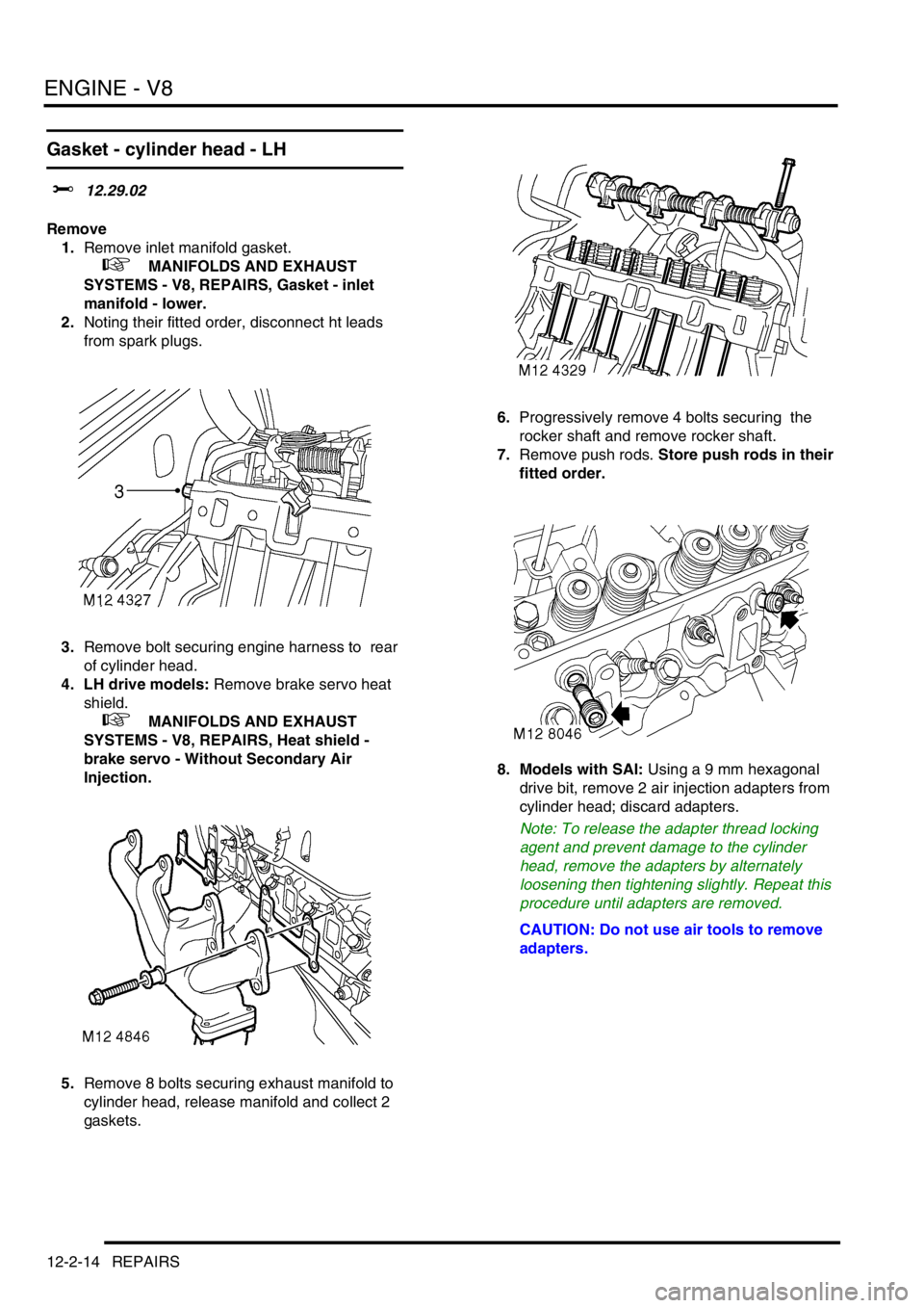
Gasket - cylinder head - LH
$% 12.29.02
Remove
1.Remove inlet manifold gasket.
+ MANIFOLDS AND EXHAUST
SYSTEMS - V8, REPAIRS, Gasket - inlet
manifold - lower.
2.Noting their fitted order, disconnect ht leads
from spark plugs.
3.Remove bolt securing engine harness to rear
of cylinder head.
4. LH drive models: Remove brake servo heat
shield.
+ MANIFOLDS AND EXHAUST
SYSTEMS - V8, REPAIRS, Heat shield -
brake servo - Without Secondary Air
Injection.
5.Remove 8 bolts securing exhaust manifold to
cylinder head, release manifold and collect 2
gaskets.6.Progressively remove 4 bolts securing the
rocker shaft and remove rocker shaft.
7.Remove push rods. Store push rods in their
fitted order.
8. Models with SAI: Using a 9 mm hexagonal
drive bit, remove 2 air injection adapters from
cylinder head; discard adapters.
Note: To release the adapter thread locking
agent and prevent damage to the cylinder
head, remove the adapters by alternately
loosening then tightening slightly. Repeat this
procedure until adapters are removed.
CAUTION: Do not use air tools to remove
adapters.
Page 171 of 1529

ENGINE - V8
12-2-16 REPAIRS
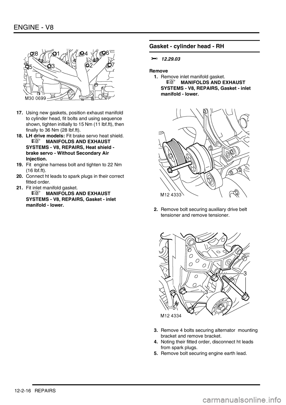
17.Using new gaskets, position exhaust manifold
to cylinder head, fit bolts and using sequence
shown, tighten initially to 15 Nm (11 lbf.ft), then
finally to 36 Nm (28 lbf.ft).
18. LH drive models: Fit brake servo heat shield.
+ MANIFOLDS AND EXHAUST
SYSTEMS - V8, REPAIRS, Heat shield -
brake servo - Without Secondary Air
Injection.
19.Fit engine harness bolt and tighten to 22 Nm
(16 lbf.ft).
20.Connect ht leads to spark plugs in their correct
fitted order.
21.Fit inlet manifold gasket.
+ MANIFOLDS AND EXHAUST
SYSTEMS - V8, REPAIRS, Gasket - inlet
manifold - lower.
Gasket - cylinder head - RH
$% 12.29.03
Remove
1.Remove inlet manifold gasket.
+ MANIFOLDS AND EXHAUST
SYSTEMS - V8, REPAIRS, Gasket - inlet
manifold - lower.
2.Remove bolt securing auxiliary drive belt
tensioner and remove tensioner.
3.Remove 4 bolts securing alternator mounting
bracket and remove bracket.
4.Noting their fitted order, disconnect ht leads
from spark plugs.
5.Remove bolt securing engine earth lead.