Page 302 of 1529
ENGINE MANAGEMENT SYSTEM - V8
DESCRIPTION AND OPERATION 18-2-3
1Mass air flow/ inlet air temperature sensor
2Fuel injectors
3High tension leads/spark plugs
4Fuel pump relay
5ATC compressor clutch relay/ cooling fan relay
6Throttle position sensor
7Heated oxygen sensor
8Idle air control valve
9Ignition coils
10Engine coolant temperature sensor
11Crankshaft speed and position sensor
12Knock sensor
13Camshaft position sensor
Page 304 of 1529
ENGINE MANAGEMENT SYSTEM - V8
DESCRIPTION AND OPERATION 18-2-5
1Engine control module
2Crankshaft speed and position sensor
3Camshaft position sensor
4Engine coolant temperature sensor
5Mass air flow/ inlet air temperature sensor
6Throttle position sensor
7Heated oxygen sensors
8Fuel injectors
9Idle air control valve
10Fuel pump relay
11EVAP canister
12EVAP canister vent valve
13EVAP canister purge valve
14Fuel tank pressure sensor15Ignition coils
16Knock sensor
17Spark plugs
18High/ Low ratio switch
19Malfunction indication lamp
20Diagnostic connector
21Air temperature control clutch relay
22Air temperature control cooling fan relay
23ATC ECU
24CAN link to EAT
25SLABS ECU
26BCU
27Instrument cluster
28Thermostat monitoring sensor (where fitted)
Page 344 of 1529

ENGINE MANAGEMENT SYSTEM - V8
DESCRIPTION AND OPERATION 18-2-45
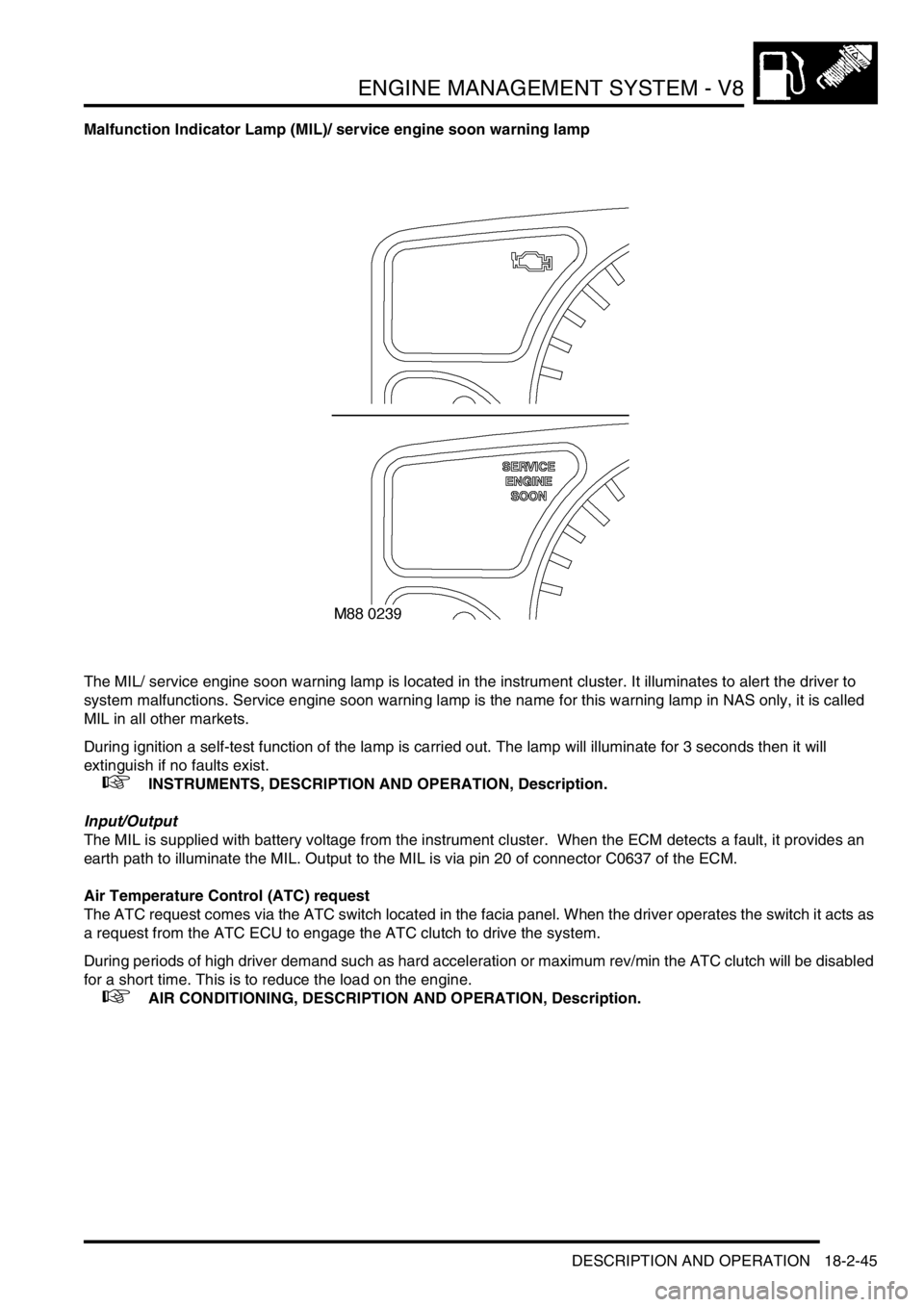
Malfunction Indicator Lamp (MIL)/ service engine soon warning lamp
The MIL/ service engine soon warning lamp is located in the instrument cluster. It illuminates to alert the driver to
system malfunctions. Service engine soon warning lamp is the name for this warning lamp in NAS only, it is called
MIL in all other markets.
During ignition a self-test function of the lamp is carried out. The lamp will illuminate for 3 seconds then it will
extinguish if no faults exist.
+ INSTRUMENTS, DESCRIPTION AND OPERATION, Description.
Input/Output
The MIL is supplied with battery voltage from the instrument cluster. When the ECM detects a fault, it provides an
earth path to illuminate the MIL. Output to the MIL is via pin 20 of connector C0637 of the ECM.
Air Temperature Control (ATC) request
The ATC request comes via the ATC switch located in the facia panel. When the driver operates the switch it acts as
a request from the ATC ECU to engage the ATC clutch to drive the system.
During periods of high driver demand such as hard acceleration or maximum rev/min the ATC clutch will be disabled
for a short time. This is to reduce the load on the engine.
+ AIR CONDITIONING, DESCRIPTION AND OPERATION, Description.
Page 345 of 1529
ENGINE MANAGEMENT SYSTEM - V8
18-2-46 DESCRIPTION AND OPERATION
Input/Output
The operation of the ATC request is via a switch being connected to earth. Voltage is supplied via pin 38 of connector
C0637 of the ECM, at the point at when the switch is pressed the connection is made and the ATC clutch is engaged.
The ATC request can fail as follows:
lOpen circuit.
lShort circuit to voltage supply.
lShort circuit to vehicle earth.
lWiring loom fault.
In the event of an ATC request failure, the ATC system does not work.
Should a malfunction of the component occur the following fault codes may be evident and can be retrieved by
TestBook.
P Code J2012 Description Land Rover Description
P1535 Air conditioning compressor request
malfunctionATC requested when not in standby mode
Page 346 of 1529

ENGINE MANAGEMENT SYSTEM - V8
DESCRIPTION AND OPERATION 18-2-47
ATC compressor clutch relay
The ATC compressor clutch relay is located in the engine compartment fuse box. It is a four pin normally open relay.
The relay must be energised to drive the ATC compressor clutch.
Input/Output
The ECM provides the earth for the relay coil to allow the relay contacts to close and the ATC clutch drive to receive
battery voltage. The ECM uses a transistor as a switch to generate an open circuit in the earth path of the relay coil.
When the ECM opens the earth path, the return spring in the relay will pull the contacts apart to shut down the ATC
clutch drive.
Input to the ATC clutch relay switching contacts is via fuse 6 located in the engine compartment fuse box. The relay
coils are supplied with battery voltage from the main relay, also located in the engine compartment fuse box. The earth
path for the relay coil is via pin 29 of the ECM C0657 connector. When the relay is energised the output from the
switching contacts goes directly to the ATC compressor clutch.
The ATC clutch relay can fail in the following ways:
lRelay open circuit.
lShort circuit to vehicle supply.
lShort circuit to vehicle earth.
lBroken return spring.
In the event of an ATC clutch relay failure, the ATC does not work.
Should a malfunction of the component occur, the following fault codes may be evident and can be retrieved by
TestBook.
P Code J2012 Description Land Rover Description
P1536 Air conditioning compressor request range/
performanceATC compressor clutch relay open circuit
P1537 Air conditioning compressor request low input ATC compressor clutch relay short to earth
P1538 Air conditioning compressor request high input ATC compressor clutch relay short to battery supply
Page 360 of 1529
ENGINE MANAGEMENT SYSTEM - V8
DESCRIPTION AND OPERATION 18-2-61
DESCRIPTION AND OPERAT ION
Cruise control component layout
1Cruise control ECU
2Cruise control master switch
3SET+ switch
4RES switch
5Brake pedal switch
6Clutch pedal switch7BCU
8Vacuum pump assembly
9Pneumatic actuator
10SLABS ECU
11Automatic gear selector lever
Page 361 of 1529
ENGINE MANAGEMENT SYSTEM - V8
18-2-62 DESCRIPTION AND OPERATION
Cruise control block diagram
1SLABS ECU
2BCU
3Cruise control master switch
4SET+ switch
5RES switch
6Brake pedal switch7Clutch pedal switch
8Cruise control ECU
9Vacuum pump assembly incorporating
pneumatic actuator
10Automatic gear selector lever
Page 362 of 1529

ENGINE MANAGEMENT SYSTEM - V8
DESCRIPTION AND OPERATION 18-2-63
Description - cruise control
General
All markets have a common cruise control system. The cruise control system, when activated, regulates vehicle
speed. The system consists of an electrical sub-system and a mechanical sub-system.
The electrical sub-system consists of the following components:
lCruise control master switch (on/off switch).
lSET+ switch.
lRES switch.
lCruise control ECU.
lVacuum pump assembly.
lBrake pedal switch.
lClutch pedal switch (manual gearbox only).
lSLABS ECU (speed signal).
lBCU (brake pedal switch and automatic gearbox gear selector lever position signal).
The mechanical sub-system consists of the following components:
lPneumatic actuator.
lVacuum pump.
The cruise control ECU controls the cruise control system. It is located on the right hand A post.
The system has diagnostic capabilities through TestBook.
WARNING: To avoid the risk of losing control of the vehicle, do not use cruise control on winding, snow
covered or slippery roads, or in traffic conditions where a constant speed cannot be safely maintained. In
these conditions and at any time the system is not being used, ensure the cruise control switch is OFF.