Page 1352 of 1529
ALARM SYSTEM AND HORN
REPAIR 86-4-29
Coil - passive immobilisation
$% 86.77.35
Remove
1.Remove steering column nacelle.
+ STEERING, REPAIRS, Nacelle -
steering column.
2.Release passive coil from steering lock.
3.Disconnect illumination bulb holder and
multiplug and remove passive coil.
Refit
1.Position passive coil, connect multiplug and
illumination bulb holder.
2.Fit passive coil to steering lock.
3.Fit steering column nacelle.
+ STEERING, REPAIRS, Nacelle -
steering column.
Page 1358 of 1529
WINDOWS
DESCRIPTION AND OPERATION 86-5-5
Front window switches
The front window switches are non-latching rocker switches located in the center console. The front window switches
contain illumination bulbs that operate when the side lamps or headlamps are on.
The front window switches provide earth signals to the BCU. The BCU determines which direction to operate the front
window motors.
TestBook will monitor the real time status of the front window switches.
Page 1446 of 1529

DRIVING AIDS
DESCRIPTION AND OPERATION 86-8-9
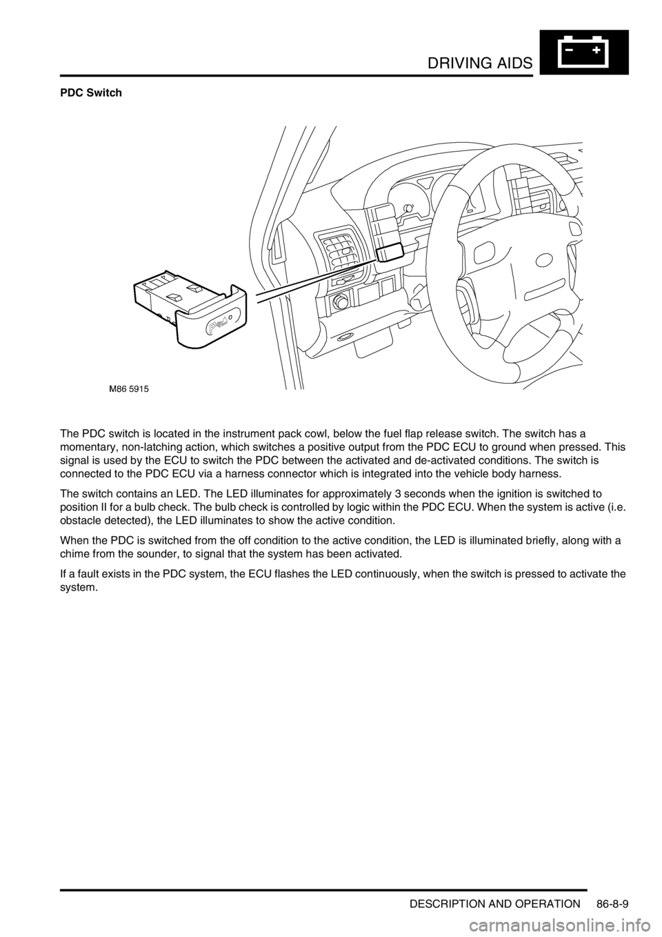
PDC Switch
The PDC switch is located in the instrument pack cowl, below the fuel flap release switch. The switch has a
momentary, non-latching action, which switches a positive output from the PDC ECU to ground when pressed. This
signal is used by the ECU to switch the PDC between the activated and de-activated conditions. The switch is
connected to the PDC ECU via a harness connector which is integrated into the vehicle body harness.
The switch contains an LED. The LED illuminates for approximately 3 seconds when the ignition is switched to
position II for a bulb check. The bulb check is controlled by logic within the PDC ECU. When the system is active (i.e.
obstacle detected), the LED illuminates to show the active condition.
When the PDC is switched from the off condition to the active condition, the LED is illuminated briefly, along with a
chime from the sounder, to signal that the system has been activated.
If a fault exists in the PDC system, the ECU flashes the LED continuously, when the switch is pressed to activate the
system.
Page 1488 of 1529

INSTRUMENTS
DESCRIPTION AND OPERATION 88-5
Description
General
The instrument pack consists of four analogue dials, four warning lamp packs and a Liquid Crystal Display (LCD)
odometer.
The four dials are used to indicate:
lRoad speed.
lEngine speed.
lFuel tank level.
lEngine coolant temperature.
The dials are driven by a microprocessor from information received from the serial communication link. Information
input is received as either:
lDigital.
lAnalogue.
lPulse train.
lPulse Width Modulation (PWM).
The LCD provides information for:
lOdometer.
lTrip distance.
lSelected gear (on vehicles fitted with an automatic gearbox).
A trip reset button is provided to zero the trip display, this button also allows the selection of "miles" or "kilometres"
for the display. A photocell controls the illumination of the LCD, maintaining contrast of the display during ambient light
changes.
Within the four warning lamp packs there are 28 lamps. A long life bulb illuminates the high beam warning lamp and
the rest of the warning lamps are illuminated by Light Emitting Diodes (LED's). All warning lamp legends are invisible
until lit. When lit the symbols are illuminated on a black background.
The warning lamps illuminate in one of four colours. The colour indicates the level of importance to the driver, as
follows:
lRed = warning.
lAmber = caution.
lGreen = system operative.
lBlue = main beam operative.
The first warning lamp pack is located in the top left-hand side of the instrument pack and contains the following
warning lamps:
lTraction control warning lamp.
lTransfer box in neutral warning lamp.
lDifferential lock warning lamp
lOverspeed warning lamp (activated for gulf market only).
lBrake system warning lamp.
lHill Descent Control (HDC) information warning lamp.
lMalfunction Indicator Lamp (MIL)/ SERVICE ENGINE SOON warning lamp.
The second warning lamp pack is located in the centre of the instrument pack and contains the following warning
lamps:
lDirection indicator warning lamps.
lHigh beam warning lamp.
lAnti-lock brake system warning lamp.
Page 1498 of 1529
INSTRUMENTS
DESCRIPTION AND OPERATION 88-15
Instrument illumination
Dimmer switch
The instrument pack contains 3 bulbs to illuminate the dials. Depending on market the bulbs are illuminated either
from the side lamps feed with no dimmer control or from a PWM dimmer control located on the dashboard. A PWM
dimmer is used so finer control of the instrument illumination can be achieved.
The input is either direct from the side lamp power feed or from the PWM dimmer control. The instrument pack
provides the earth path to illuminate the lamps.
Page 1500 of 1529
INSTRUMENTS
DESCRIPTION AND OPERATION 88-17
Main beam warning lamp
The main beam warning lamp within the instrument pack utilises a clear 14 volt 2 watt long life bulb and a blue legend.
The bulb illuminates when the headlamps are switched to main beam, providing the driver with a visible warning.
There is no self-test performed at ignition on for this warning lamp.
Operating the main beam switch provides the Intelligent Driver Module (IDM) with battery voltage. This feed activates
the IDM to supply the power for the main beam warning lamp. The earth path is provided through the instrument pack.
Page:
< prev 1-8 9-16 17-24