Page 1411 of 1529
HARNESSES
86-7-6 REPAIRS
47.Disconnect multiplug from fuel flap solenoid.
48.Remove nut securing alarm sounder to RH
lower 'E' post.
49.Disconnect multiplug from alarm sounder.
50.Remove alarm sounder. 51.Remove grommet and feed harness from rear
bumper to upper 'E' post.
52.Remove nut securing earth headers to RH 'E'
post.
53.Feed harness to air conditioning ducting.
54.Remove 4 cable ties securing harness to centre
of roof.
55.With assistance, remove harness from air
conditioning ducting and remove from vehicle.
Page 1412 of 1529

HARNESSES
REPAIRS 86-7-7
Refit
1.With assistance, position harness to air
conditioning ducting and secure with cable ties.
2.Secure harness to sunroof harness with cable
clips.
3.Connect multiplug to RF receiver.
4.Feed harness to LH and RH upper 'E' posts.
5.Feed harness through 'E' post to tail lamp and
rear bumper and secure with grommet.
6.Connect multiplug to fuel flap solenoid and
alarm sounder.
7.Position alarm sounder to rear quarter and
secure with nut to 9 Nm (7 lbf.ft).
8.Position both RH earth header to 'E' post and
tighten nut to 10 Nm (7 lbf.ft).
9.Feed tail door harness through 'E' post and
secure with grommet.
10.Position harness sleeve to outer edge of door
and pull harness through door.
11.Secure harness to tail door with clips.
12.Connect washer tube to rear of wiper arm.
13.Remove tape from draw string and secure to
CHMSL harness.
14.Draw harness through tail door and connect
Lucars to CHMSL.
15.Fit CHMSL cover and secure with screws.
16.Connect multiplug to door lock switch.
17.Connect Lucars to HRW.
18.Connect multiplug to rear wiper motor.
19.Connect multiplug to door latch.
20.Fit plastic sheet to tail door, ensuring it aligns
with witness marks.
21.Fit tail door trim casing.
+ DOORS, REPAIRS, Trim casing - tail
door.
22.Connect Lucar to radio aerial RH amplifier.
23.Secure harness to RH side of body with clips
and retainers.
24.Position both LH earth header to 'E' post and
tighten nut to 10 Nm (7 lbf.ft).
25.Connect multiplugs to both tail/flasher lamps
and secure harness to bumper with clips.
26.Fit both rear tail lamps.
+ LIGHTING, REPAIRS, Lamp - tail.
27.Secure harness to rear LH side of body with 6
cable clips.
28.Connect 2 Lucars to rear air conditioning unit.
29.Fit both luggage compartment trim casings.
+ INTERIOR TRIM COMPONENTS,
REPAIRS, Trim casing - side - loadspace.
30.Feed harness into position for rear interior light.
31.Connect Lucar to radio aerial LH amplifier.
32.Secure harness to body with cable ties clips
and retainers.
33.Secure air conditioning ducting to body with
rivets.
34.Feed harness to LH lower 'A' post. 35.Secure harness to LH side of body with cable
tie clips and retainers.
36.Connect and secure multiplugs to lower LH 'A'
post.
37.Feed harness through roof to centre.
38.Secure harness behind bonnet release cable.
39.Connect rear washer pipe at lower 'A' post and
secure with clip.
40.Secure harness to roof with clips.
41.Connect multiplug to interior mirror, ARC
accelerometer.
42.Position sound deadening panels and secure
with clips.
43.Fit headlining.
+ INTERIOR TRIM COMPONENTS,
REPAIRS, Headlining.
44.Fit fascia panel.
+ INTERIOR TRIM COMPONENTS,
REPAIRS, Fascia.
Page 1413 of 1529
HARNESSES
86-7-8 REPAIRS
Harness - engine - V8
$% 86.70.17
Remove
1.Remove upper inlet manifold.
+ MANIFOLDS AND EXHAUST
SYSTEMS - V8, REPAIRS, Gasket - inlet
manifold - upper - Without Secondary Air
Injection.
2.Disconnect injector multiplugs, release harness
from fuel rail.
3.Disconnect ignition coil multiplugs.4.Release and disconnect both HS
2O sensor
multiplugs.
5.Disconnect CKP sensor multiplug.
Page 1419 of 1529
HARNESSES
86-7-14 REPAIRS
13.Disconnect multiplug from fuel temperature
sensor.
14.Release harness clip from coolant pipe. 15.Disconnect multiplug from MAP sensor.
16.Disconnect 4 glow plug connectors.
17.Release nut securing battery lead to alternator
and disconnect multiplug from alternator.
18.Disconnect injector multiplug.
19.Remove 2 bolts securing harness to front of
cylinder head.
20.Disconnect multiplug from ECT sensor.
Page 1420 of 1529

HARNESSES
REPAIRS 86-7-15
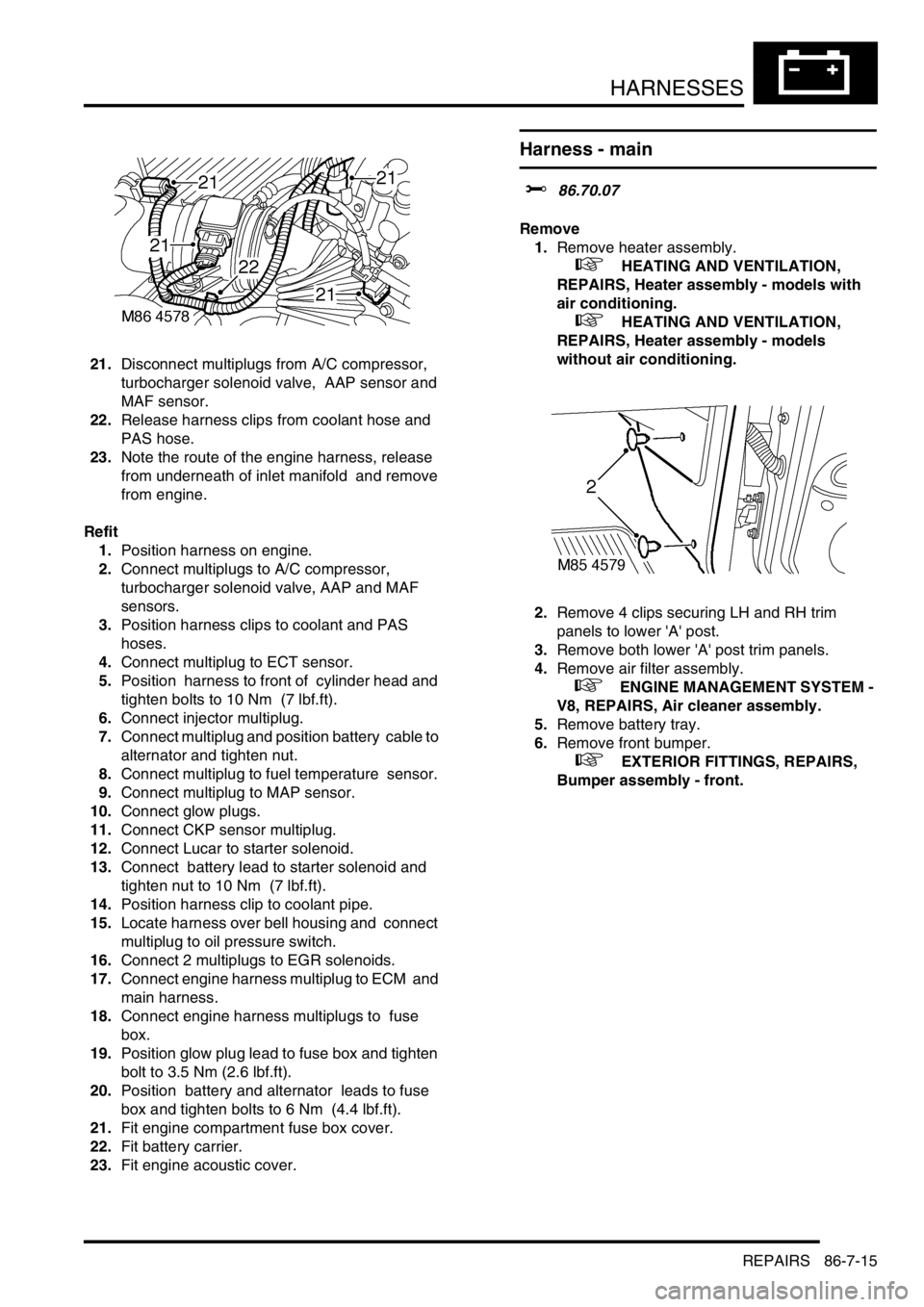
21.Disconnect multiplugs from A/C compressor,
turbocharger solenoid valve, AAP sensor and
MAF sensor.
22.Release harness clips from coolant hose and
PAS hose.
23.Note the route of the engine harness, release
from underneath of inlet manifold and remove
from engine.
Refit
1.Position harness on engine.
2.Connect multiplugs to A/C compressor,
turbocharger solenoid valve, AAP and MAF
sensors.
3.Position harness clips to coolant and PAS
hoses.
4.Connect multiplug to ECT sensor.
5.Position harness to front of cylinder head and
tighten bolts to 10 Nm (7 lbf.ft).
6.Connect injector multiplug.
7.Connect multiplug and position battery cable to
alternator and tighten nut.
8.Connect multiplug to fuel temperature sensor.
9.Connect multiplug to MAP sensor.
10.Connect glow plugs.
11.Connect CKP sensor multiplug.
12.Connect Lucar to starter solenoid.
13.Connect battery lead to starter solenoid and
tighten nut to 10 Nm (7 lbf.ft).
14.Position harness clip to coolant pipe.
15.Locate harness over bell housing and connect
multiplug to oil pressure switch.
16.Connect 2 multiplugs to EGR solenoids.
17.Connect engine harness multiplug to ECM and
main harness.
18.Connect engine harness multiplugs to fuse
box.
19.Position glow plug lead to fuse box and tighten
bolt to 3.5 Nm (2.6 lbf.ft).
20.Position battery and alternator leads to fuse
box and tighten bolts to 6 Nm (4.4 lbf.ft).
21.Fit engine compartment fuse box cover.
22.Fit battery carrier.
23.Fit engine acoustic cover.
Harness - main
$% 86.70.07
Remove
1.Remove heater assembly.
+ HEATING AND VENTILATION,
REPAIRS, Heater assembly - models with
air conditioning.
+ HEATING AND VENTILATION,
REPAIRS, Heater assembly - models
without air conditioning.
2.Remove 4 clips securing LH and RH trim
panels to lower 'A' post.
3.Remove both lower 'A' post trim panels.
4.Remove air filter assembly.
+ ENGINE MANAGEMENT SYSTEM -
V8, REPAIRS, Air cleaner assembly.
5.Remove battery tray.
6.Remove front bumper.
+ EXTERIOR FITTINGS, REPAIRS,
Bumper assembly - front.
Page 1426 of 1529
HARNESSES
REPAIRS 86-7-21
48.Disconnect multiplug from bonnet switch.
49.Disconnect 3 multiplugs from ABS modulator
and multiplug from ABS sensor. 50.Release LH indicator repeater lamp.
51.Disconnect multiplug from repeater lamp.
52.Remove repeater lamp.
53.Attach draw string to repeater lamp harness.
54.Pull harness into engine bay, remove draw
string and secure.
55.Disconnect multiplug from fuel cut-off switch.
56.Remove plenum moulding.
+ HEATING AND VENTILATION,
REPAIRS, Plenum Air Intake.
Page 1432 of 1529

HARNESSES
REPAIRS 86-7-27
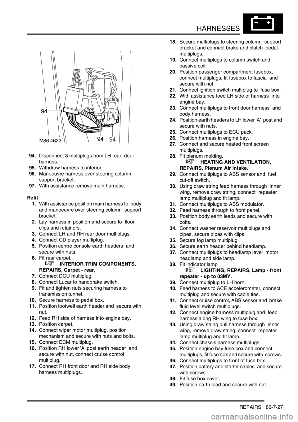
94.Disconnect 3 multiplugs from LH rear door
harness.
95.Withdraw harness to interior.
96.Manoeuvre harness over steering column
support bracket.
97.With assistance remove main harness.
Refit
1.With assistance position main harness to body
and manoeuvre over steering column support
bracket.
2.Lay harness in position and secure to floor
clips and retainers.
3.Connect LH and RH rear door multiplugs.
4.Connect CD player multiplug.
5.Position centre console earth headers and
secure with nuts.
6.Fit rear carpet.
+ INTERIOR TRIM COMPONENTS,
REPAIRS, Carpet - rear.
7.Connect DCU multiplug.
8.Connect Lucar to handbrake switch.
9.Fit and tighten nuts securing harness to
transmission tunnel.
10.Secure harness to pedal box.
11.Position footwell earth header and secure with
nut.
12.Feed RH side of harness into engine bay.
13.Position carpet.
14.Connect wiper motor multiplug, position
mechanism and secure with nuts and bolts.
15.Connect ECM multiplug.
16.Position RH lower 'A' post earth header and
secure with nut, connect cruise control
multiplug.
17.Connect RH front door and RH side body
harness multiplugs. 18.Secure multiplugs to steering column support
bracket and connect brake and clutch pedal
multiplugs.
19.Connect multiplugs to column switch and
passive coil.
20.Position passenger compartment fusebox,
connect multiplugs, fit fusebox to fascia and
secure with nut.
21.Connect ignition switch multiplug to fuse box.
22.With assistance feed LH side of harness into
engine bay.
23.Connect multiplugs to front door harness and
body harness.
24.Position earth headers to LH lower 'A' post and
secure with nuts.
25.Connect multiplugs to ECU pack.
26.Position harness in engine bay.
27.Connect and secure heated front screen
multiplugs.
28.Fit plenum molding.
+ HEATING AND VENTILATION,
REPAIRS, Plenum Air Intake.
29.Connect multiplugs to ABS sensor and fuel
cut-off switch.
30.Using draw string feed harness through inner
wing, remove draw string, connect repeater
lamp multiplug and fit lamp.
31.Connect multiplugs to ABS modulator.
32.Feed harness through to front panel.
33.Position body earth leads and secure with
bolts.
34.Connect washer reservoir multiplugs and
pipes, secure pipes with clips.
35.Secure fog lamp multiplug.
36.Secure earth header behind headlamp.
37.Connect multiplugs to headlamp level motor,
headlamp and side lamp.
38.Fit indicator lamp
+ LIGHTING, REPAIRS, Lamp - front
repeater - up to 03MY.
39.Connect multiplug to LH horn.
40.Feed harness to ACE accelerometer, connect
multiplug and secure with cable ties.
41.Connect cruise control, ABS sensor and brake
fluid level switch multiplugs.
42.Connect engine harness multiplug and feed
harness along RH wing to fuse box.
43.Using draw string pull harness through inner
wing, remove draw string, connect repeater
lamp multiplug and fit lamp.
44.Connect chassis harness multiplugs.
45.Position engine bay fuse box and connect
multiplugs, fit fuse box and secure with screws.
46.Connect multiplugs to front of fuse box.
47.Position battery and starter cables and secure
with screws.
48.Fit fuse box cover.
49.Position earth lead and secure with nut.
Page 1446 of 1529

DRIVING AIDS
DESCRIPTION AND OPERATION 86-8-9
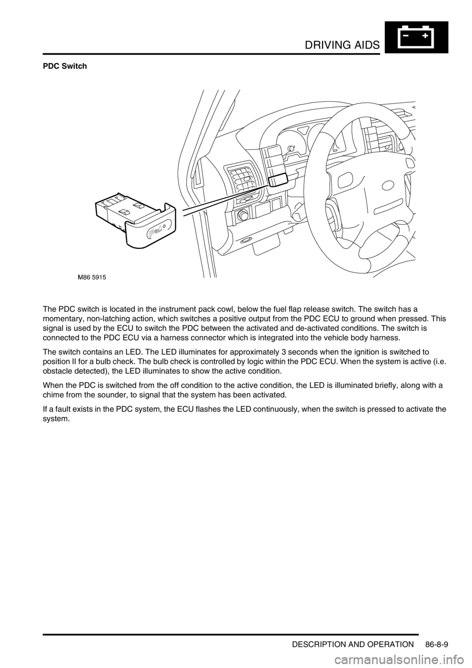
PDC Switch
The PDC switch is located in the instrument pack cowl, below the fuel flap release switch. The switch has a
momentary, non-latching action, which switches a positive output from the PDC ECU to ground when pressed. This
signal is used by the ECU to switch the PDC between the activated and de-activated conditions. The switch is
connected to the PDC ECU via a harness connector which is integrated into the vehicle body harness.
The switch contains an LED. The LED illuminates for approximately 3 seconds when the ignition is switched to
position II for a bulb check. The bulb check is controlled by logic within the PDC ECU. When the system is active (i.e.
obstacle detected), the LED illuminates to show the active condition.
When the PDC is switched from the off condition to the active condition, the LED is illuminated briefly, along with a
chime from the sounder, to signal that the system has been activated.
If a fault exists in the PDC system, the ECU flashes the LED continuously, when the switch is pressed to activate the
system.