1999 LAND ROVER DISCOVERY fuel
[x] Cancel search: fuelPage 1326 of 1529

ALARM SYSTEM AND HORN
DESCRIPTION AND OPERATION 86-4-3
1Theft deterrent LED
2Receiver
3Volumetric sensors
4Central door locking switch
5Body Control Unit (BCU)
6Bonnet activated alarm switch
7Vehicle horn
8Alarm sounder
9Fuel cut off switch
10Fuel flap release switch
11Door latch switches, drivers door key lock/
unlock switches
12Battery Backed Up Sounder (BBUS)
13Passive remobilisation exciter coil
Page 1327 of 1529

ALARM SYSTEM AND HORN
86-4-4 DESCRIPTION AND OPERATION
Alarm system block diagram
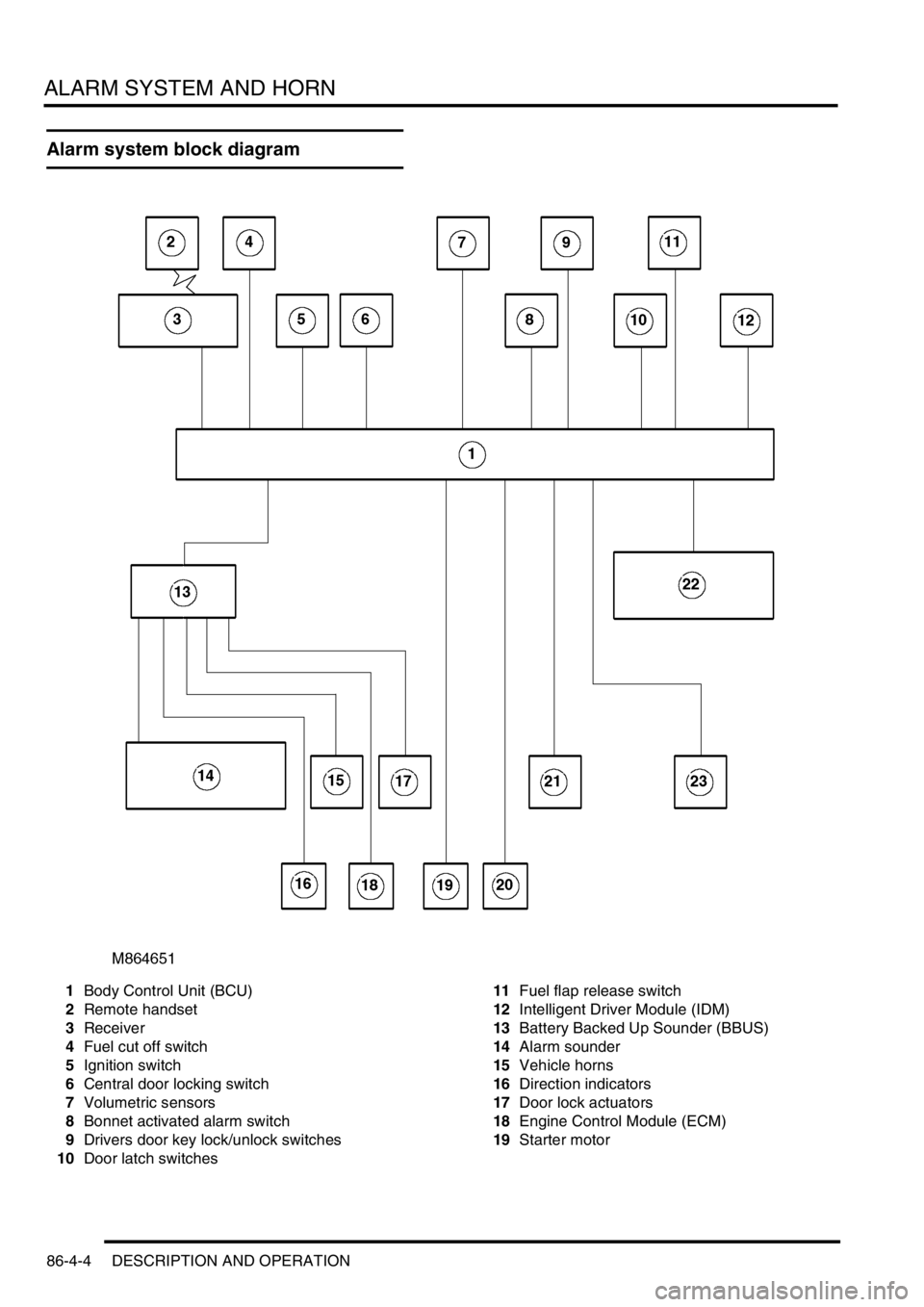
1Body Control Unit (BCU)
2Remote handset
3Receiver
4Fuel cut off switch
5Ignition switch
6Central door locking switch
7Volumetric sensors
8Bonnet activated alarm switch
9Drivers door key lock/unlock switches
10Door latch switches 11Fuel flap release switch
12Intelligent Driver Module (IDM)
13Battery Backed Up Sounder (BBUS)
14Alarm sounder
15Vehicle horns
16Direction indicators
17Door lock actuators
18Engine Control Module (ECM)
19Starter motor
Page 1328 of 1529

ALARM SYSTEM AND HORN
DESCRIPTION AND OPERATION 86-4-5
Description
General
The anti-theft system deters the theft of the vehicle with both active and passive systems. The active systems monitor
the vehicle perimeter and, in some markets the vehicle interior, for intrusion. If the system detects intrusion, an alarm
sounds. The passive systems include a vehicle immobiliser as well as protection against intrusion through super
locking the doors. The vehicle is immobilised whenever the ignition key is removed from the ignition switch. Super
locking prevents the interior door handles from opening the doors. In addition, there are many features and functions
that enhance system operation.
It is possible to perform the various functions associated with the anti-theft system remotely. To accomplish this, the
handset generates a radio frequency when the lock button or unlock button is depressed. This signal is transmitted
to the Body Control Unit (BCU) via a receiver located in front of rear sunroof beneath the headlining. Precise alignment
of the handset to the receiver is not necessary. The approximate operating range between the handset and the
receiver is 10 metres (33 feet).
It is important to understand the configuration of the system on each particular vehicle. There are many
different combinations of features with dedicated operating modes. System configuration for each vehicle
can be determined using TestBook.
The anti-theft system is controlled centrally by the BCU, which is located below and behind the passenger glovebox.
A serial communication link communicates between the Intelligent Driver Module (IDM) located within the fusebox,
the BCU and the LED located in the instrument panel.
The state of the alarm is stored in the BCU. If the battery is disconnected while the alarm is armed, the alarm will be
triggered when the battery is reconnected.
NOTE: Disconnecting the battery while the alarm is armed triggers the alarm. Always disarm the alarm system before
disconnecting the battery.
The BCU also receives inputs from the following components:
lIgnition key in sensor.
lIgnition switch.
lFuel cut off switch.
lFuel flap release switch.
The BCU also interacts with the following components:
lStarter relay.
lVehicle horns.
lDirection indicators.
lFuel flap release actuator.
lCourtesy lamps.
Page 1340 of 1529

ALARM SYSTEM AND HORN
DESCRIPTION AND OPERATION 86-4-17
Operation
Standard system functions
All vehicles have the following functions as standard.
lLocking.
lUnlocking.
lFuel cut off switch unlocking.
lInternal locking.
lElectric fuel flap release.
Locking
The doors are locked by pressing the lock button on the handset or by locking the vehicle from the driver's door with
the key.
In order to lock the vehicle, the following conditions must be met:
lThe driver's door is closed.
lThe ignition is off.
lThe fuel cut off switch is not tripped.
lThe bonnet is closed.
lThe vehicle is not super locked.
Depending on system configuration a mislock occurs if these conditions are not met. The doors may lock (depending
on condition not met) and the system may not fully arm, depending on configuration of the system. If a mislock occurs
an audible warning is emitted and the vehicle becomes partially armed.
Unlocking
The doors are unlocked by pressing the unlock button on the handset or by unlocking the vehicle from the driver's
door with the key. This may unlock only the driver's door or it may unlock all doors depending on system configuration.
Fuel cut off switch unlocking
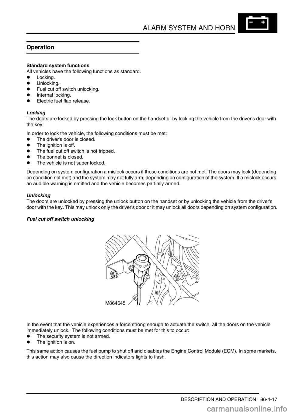
In the event that the vehicle experiences a force strong enough to actuate the switch, all the doors on the vehicle
immediately unlock. The following conditions must be met for this to occur:
lThe security system is not armed.
lThe ignition is on.
This same action causes the fuel pump to shut off and disables the Engine Control Module (ECM). In some markets,
this action may also cause the direction indicators lights to flash.
Page 1341 of 1529

ALARM SYSTEM AND HORN
86-4-18 DESCRIPTION AND OPERATION
Internal locking
Internal locking allows the doors to be locked / unlocked from a central position using switches on the instrument
panel. The internal unlock switch will not operate if the vehicle is super locked.
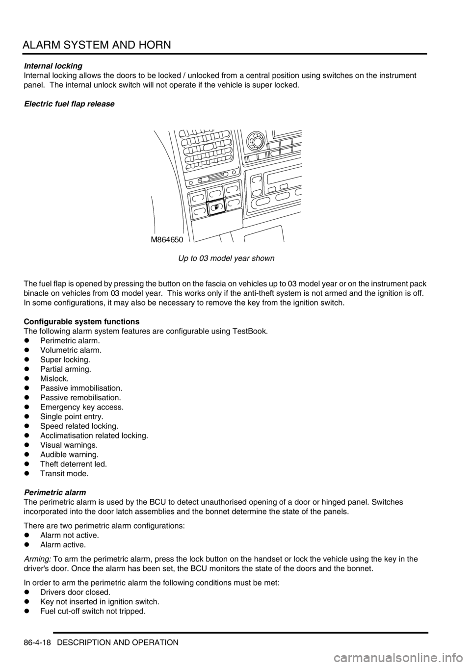
Electric fuel flap release
Up to 03 model year shown
The fuel flap is opened by pressing the button on the fascia on vehicles up to 03 model year or on the instrument pack
binacle on vehicles from 03 model year. This works only if the anti-theft system is not armed and the ignition is off.
In some configurations, it may also be necessary to remove the key from the ignition switch.
Configurable system functions
The following alarm system features are configurable using TestBook.
lPerimetric alarm.
lVolumetric alarm.
lSuper locking.
lPartial arming.
lMislock.
lPassive immobilisation.
lPassive remobilisation.
lEmergency key access.
lSingle point entry.
lSpeed related locking.
lAcclimatisation related locking.
lVisual warnings.
lAudible warning.
lTheft deterrent led.
lTransit mode.
Perimetric alarm
The perimetric alarm is used by the BCU to detect unauthorised opening of a door or hinged panel. Switches
incorporated into the door latch assemblies and the bonnet determine the state of the panels.
There are two perimetric alarm configurations:
lAlarm not active.
lAlarm active.
Arming: To arm the perimetric alarm, press the lock button on the handset or lock the vehicle using the key in the
driver's door. Once the alarm has been set, the BCU monitors the state of the doors and the bonnet.
In order to arm the perimetric alarm the following conditions must be met:
lDrivers door closed.
lKey not inserted in ignition switch.
lFuel cut-off switch not tripped.
Page 1342 of 1529

ALARM SYSTEM AND HORN
DESCRIPTION AND OPERATION 86-4-19
Disarming: To prevent the alarm from triggering when entering the vehicle, the alarm system must be disarmed with
the key or the handset.
There are two perimetric alarm disarming configurations:
lAlways disarm with key.
lOnly disarm with key if locked with key.
The perimetric alarm can be disarmed by unlocking the vehicle with the handset or by using the key in the driver's
door lock, depending on system configuration.
NOTE: The “only disarm with key if locked with key” configuration prevents the alarm from being disarmed by
unlocking the vehicle with the handset if the vehicle has been locked by the key. In this situation the Emergency Key
Access (EKA) code must be entered to disarm the alarm.
In order for the alarm to trigger, the following conditions must be met:
lPerimetric alarm armed.
lBonnet or door opened.
Once triggered, the alarm will remain triggered for 30 seconds before resetting.
Volumetric alarm
The volumetric alarm is used by the BCU to detect movement within the vehicle. This allows the alarm to be triggered
if a window is smashed in an attempt to gain access to the vehicle.
There are two volumetric alarm configurations:
lVolumetric alarm not active.
lVolumetric alarm active.
Two sensors, which transmit and receive ultrasonic signals, detect movement within the vehicle. Theses sensors
detect any change in air movement within the vehicle and then supply the BCU a signal to activate the alarm. Fifteen
seconds after the vehicle is locked with the handset or the key the volumetric alarm is armed. This delay is
incorporated into the BCU software to prevent accidental or nuisance triggering of the alarm.
In order to arm the volumetric alarm, the following conditions must be met:
lDriver's door closed.
lKey not inserted in ignition.
lFuel cut-off switch not tripped.
To prevent the alarm from triggering when entering the vehicle, the alarm system must be disarmed with the key or
the handset.
There are two volumetric alarm disarming configurations:
lAlways disarm with key.
lOnly disarm with key if locked with key.
The volumetric alarm can be disarmed by unlocking the driver's door with the key or the handset, depending on
system configuration.
NOTE: The “only disarm with key if locked with key” configuration prevents the alarm from being disarmed by
unlocking the vehicle with the handset if the vehicle has been locked by the key. In this situation the EKA code must
be entered to disarm the alarm.
In order for the alarm to trigger, the following conditions must be met:
lVolumetric alarm armed.
lVolumetric sensors triggered.
Once triggered, the alarm will remain triggered for 30 seconds before resetting.
Page 1343 of 1529

ALARM SYSTEM AND HORN
86-4-20 DESCRIPTION AND OPERATION
Super locking
Super locking prevents the use of the interior door handles to unlock and open the vehicle doors. This prevents the
doors from being opened if the window be smashed in an attempt to gain access to the vehicle.
There are four configurations for super locking:
lNo super locking.
lSuper locking on single handset press only (no key activated super locking).
lSuper locking on single handset press or single key turn.
lSuper locking on double handset press or double key turn.
To super lock, press the lock button on the handset once or twice within one second depending on system
configuration. In some configurations, it is also possible to super lock the vehicle using the key in the driver's door.
This also may require one or two turns of the key in the lock direction. If two turns of the key are required to activate
super locking, the two turns must occur within one second of each other.
In order to super lock the vehicle, the following conditions must be met:
lAll door are closed.
lThe ignition is off.
lThe fuel cut-off switch is not tripped.
Partial arming
Partial arming allows protection of as much of the vehicle as possible if the alarm is armed with one or more doors or
the bonnet open.
Partial arming allows the vehicle alarm to be armed even if the following conditions exist. When the bonnet or door is
closed, the BCU activates the perimetric alarm and the volumetric alarm after 15 seconds have elapsed:
lThe bonnet is not closed: If the bonnet is open when the alarm is armed, the BCU activates super locking and
volumetric sensing. In this condition, the alarm enters a partially armed state. All other functions of the alarm are
active and the BCU monitors the bonnet for a change of state. If the bonnet closes, the system is completely
armed.
lThe passenger door, a rear door or the tail door is not closed: If a door is open when the alarm is armed, the BCU
does not activate super locking or volumetric sensing. In this condition the alarm enters a partially armed state.
All other alarm functions are armed and the BCU monitors the open door. If the door closes volumetric sensing
and super locking become active.
lFailure of a door latch switch: If a short circuit in the door latch switch occurs, the BCU presumes the door is not
closed. In this situation the BCU does not activate super locking or volumetric sensing. All other alarm functions
are armed.
lDamaged wiring harness: If a short circuit in the wiring harness for the door latch switch occurs, the BCU
presumes the door is not closed and does not activate super locking or volumetric sensing; all other alarm
functions are armed. If an open circuit in the wiring harness for the door latch switch occurs, the BCU presumes
the door is closed and arms the alarm as normal.
Mislock
Mislock alerts the driver that a failed attempt has been made to lock the vehicle because of the doors or the bonnet
not being fully closed.
There are six audible configurations for mislock:
lNo audible warning.
lAlarm sounder.
lVehicle horn.
lAlarm sounder and vehicle horn.
lBBUS.
lAlarm sounder, vehicle horn and BBUS.
When a failed attempt has been made to lock the vehicle, the audible warning device is switched on for 50 ms and
off for 200 ms. The BCU allows the audible warning device to operate 3 times.
Page 1344 of 1529

ALARM SYSTEM AND HORN
DESCRIPTION AND OPERATION 86-4-21
Passive immobilisation
Passive immobilisation prevents the vehicle from being started unless the authorised key is used to start the vehicle.
There are only two configurations for passive immobilisation:
lpassive immobilisation not active
lpassive immobilisation active
When the ignition is switched off, the vehicle remains mobilised for up to a maximum of 5 minutes. If however the
driver's door is opened, after 2 minutes 30 seconds, the vehicle remains in a mobilised state for a further 30 seconds.
When the timer in the BCU has expired, the vehicle is immobilised.
Once the ignition is switched on, the BCU transmits a coded signal to the ECM. If the coded signal does not
correspond to the programmed code in the ECM, the ECM is inhibited and the BCU inhibits the starting circuit.
In order for passive immobilisation to occur, the following conditions must be met:
lDriver's door closed.
lFuel cut-off switch not tripped.
lKey not inserted in ignition.
Passive remobilisation
Whenever the vehicle is immobilised, passive remobilisation of the engine occurs when the ignition is switched on,
allowing the vehicle to be started.
There are three configurations for passive remobilisation:
lPassive immobilisation not active.
lPassive immobilisation active.
lEKA with super locking on receiving good passive remobilisation exciter coil signal.
The BCU controls the passive remobilisation exciter coil (located around the ignition barrel) to generate a magnetic
field which causes the handset to transmit a remobilisation signal. The BCU receives the signal and allows the vehicle
to be started. If a valid signal from the handset is not received within one minute of the ignition being switched to
position II, the BCU stops the passive coil from generating the magnetic field.
Emergency key access
If the handset fails to operate, the engine can be remobilised by using the key to enter a unique four digit Emergency
Key Access (EKA) code.
There are three configurations for emergency key access:
lEKA not active (no immobiliser fitted).
lEKA active.
lEKA with super locking on receiving good passive remobilisation exciter coil signal.