1999 LAND ROVER DISCOVERY window
[x] Cancel search: windowPage 942 of 1529

DOORS
REPAIRS 76-1-9
Trim casing - rear door
$% 76.34.04.99
Remove
1.Remove screw securing door handle
escutcheon to door.
2.Disconnect multiplug from window switch.
3.Remove door handle escutcheon.
4.Remove 2 screws securing hand rail to door.
5.Carefully release 11 clips securing trim casing
to door.6.If fitted, disconnect multiplug from upper door
speaker.
7.Disconnect multiplug from lower door speaker.
8.Remove trim casing from door.
Refit
1.Position trim casing to door and connect door
speaker multiplug(s).
2.Secure trim casing to door with clips.
3.Fit hand rail to door and secure with screws.
4.Connect multiplug to window switch.
5.Fit escutcheon to door handle and secure with
screw.
Page 990 of 1529

SCREENS
REPAIRS 76-4-1
SCREENS REPAIRS
Glass/sealing rubber - tail door
$% 76.31.22
Remove
1.Remove spare wheel from rear door.
2.Remove centre high mounted stop lamp.
+ LIGHTING, REPAIRS, Lamp - stop -
centre high mounted (CHMSL).
3.Pull the rear wiper arm away from the glass.
4.Disconnect leads from rear window heater.
5.Ease glass sealing rubber from tail door flange
and with assistance, from inside push the glass
and sealing rubber out.
6.Remove sealing rubber from glass. Refit
1.Thoroughly clean the tail door glass mounting
flange.
2.Clean glass and fit sealing rubber. Ensure
sealing rubber is fully located onto glass.
3.Fit a draw cord into the outside groove of the
sealing rubber with cord ends situated on top
corner of bend at bottom of glass.
4.To aid assembly, lubricate the tail door glass
mounting flange with liquid soap.
5.Position the assembled glass and rubber to
outside of flange.
6.With assistance from second operator pushing
glass into door, hold one end of cord and pull
the other end carefully around the aperture,
easing the rubber seal over the flange.
7.Connect leads to rear window heater.
8.Fit centre high mounted stop lamp.
+ LIGHTING, REPAIRS, Lamp - stop -
centre high mounted (CHMSL).
9.Fit rear wiper onto glass.
10.Fit spare wheel.
Page 993 of 1529

SCREENS
76-4-4 REPAIRS
15.Apply a continuous bead of sealant to sealant
face on screen as shown.
16.With assistance, lift screen into place and align
to screen supports and tape. Ensure top
finisher is located into correct position. Lightly
press glass to fully seat sealer.
CAUTION: Do not apply heavy pressure to
the sides of the windscreen. Lightly press
windscreen from centre outwards until
edges are to required gap. Pushing sides
into position can bend windscreen and lead
to cracking in service.
17.Remove protective covers and tape.
18.Test sealer for leaks, apply additional sealer if
necessary. If water is used, allow sealer to dry
before testing. Spray water around glass and
check for leaks. Mark any area that leaks. Dry
glass and sealer then apply additional sealer.
19.Fit interior mirror to slug.
20.If applicable, connect screen heater multiplugs.
21.Fit air intake plenum.
+ HEATING AND VENTILATION,
REPAIRS, Plenum Air Intake.
CAUTION: A curing time of 6 hours is
desirable. During this time leave a window
open to ventilate the vehicle interior. If the
vehicle must be used before the curing time
has elapsed, do not drive at speed or slam
the doors with the windows closed.
CAUTION: Vehicles fitted with a passenger
airbag should not be driven for 24 hours.
Glass - body side - rear
$% 76.81.18
Introduction
The following equipment is required:
lCutting wire and handles.
lKent cutting knife.
lGlazing knife.
lWindscreen repair kit.
lSealant applicator gun.
lSuction cups.
lA felt covered table or stand to support glass.
WARNING: Wear protective gloves when
handling glass, solvents and primers.
WARNING: Wear suitable eye protection when
removing and refitting glass.
Remove
1.If fitted, disconnect coaxial cable from terminal
on glass.
2.Fit protection to exterior body work adjacent to
glass.
3.Cover body panels adjacent to glass.
4.Fit protection to internal trim adjacent to glass.
5.Cover interior of vehicle with protective sheet.
Page 994 of 1529

SCREENS
REPAIRS 76-4-5
6.From outside of vehicle, use a Kent knife and
carefully cut through sealant to release glass
from body. Any remaining sealant not
accessible with Kent knife can be severed
using cutting wire or knife.
CAUTION: Hold the cutting wire as close to
the glass as possible to prevent damage to
the body and surrounding trim.
7.Remove glass.
CAUTION: Lay glass on felt covered
supports and be careful not to damage the
obscuration band. Do not stand on edge as
this can cause chips which subsequently
develop into cracks.
Refit
1.Carefully remove sealant from body to leave a
smooth surface.
2.With assistance, fit glass without sealant to
body and apply masking tape to establish
reference marks as an alignment aid.
3.Remove glass and place aside.
4.Clean body and sealant face on glass with
solvent.
CAUTION: Do not touch cleaned or primed
surfaces with fingers.5.Apply etch primer to any bare metal on body.
6.Apply glass primer to sealant face on glass and
allow to cure.
7.Apply primer over etch primer on body.
8.Apply activator over old sealant on body.
9.Allow activator to cure.
10.Fit pre-cut nozzle to sealant cartridge, remove
lid, shake out crystals, and fit cartridge to
applicator gun. If necessary modify the nozzle
to achieve required bead section.
11.Apply a continuous bead of sealant to sealant
face on glass as shown.
12.Position glass to body and align to reference
tape.
13.Lightly press glass to ensure correct profile.
14.Secure glass with tape until sealer has cured.
15.Remove protective covers and tape.
16.If applicable, connect coaxial cable to terminal
on glass
17.Test sealer for leaks, apply additional sealer if
necessary. If water is used, allow sealer to dry
before testing. Spray water around glass and
check for leaks. Mark any area that leaks. Dry
glass and sealer then apply additional sealer.
CAUTION: A curing time of 6 hours is
desirable. During this time leave a window
open to ventilate the vehicle interior. If the
vehicle must be used before the curing time
has elapsed, do not drive at speed or slam
the doors with the windows closed.
Page 996 of 1529

SCREENS
REPAIRS 76-4-7
12.Position glass to body and align to reference
tape.
13.Lightly press glass to ensure correct profile.
14.Secure glass with tape until sealer has cured.
15.Remove protective covers and tape.
16.Test sealer for leaks, apply additional sealer if
necessary. If water is used, allow sealer to dry
before testing. Spray water around glass and
check for leaks. Mark any area that leaks. Dry
glass and sealer then apply additional sealer.
CAUTION: A curing time of 6 hours is
desirable. During this time leave a window
open to ventilate the vehicle interior. If the
vehicle must be used before the curing time
has elapsed, do not drive at speed or slam
the doors with the windows closed.
Page 1140 of 1529

CORROSION PREVENTION AND SEALING
CORROSION PREVENTION 77-4-7
The checks described above are intended to be visual only. It is not intended that the operator should remove trim
panels, finishers, rubbing strips or sound-deadening materials when checking the vehicle for corrosion and paint
damage.
With the vehicle on a lift, and using an inspection or spot lamp, visually check for the following:
lCorrosion damage and damaged paintwork, condition of underbody sealer on front and rear lower panels, sills
and wheel arches;
lDamage to underbody sealer. Corrosion in areas adjacent to suspension mountings and fuel tank fixings.
NOTE: The presence of small blisters in the underbody sealer is acceptable, providing they do not expose bare metal.
Pay special attention to signs of damage caused to panels or corrosion protection material by incorrect jack
positioning.
WARNING: It is essential to follow the correct jacking and lifting procedures.
With the vehicle lowered, visually check for evidence of damage and corrosion on all visible painted areas, in
particular the following:
lFront edge of bonnet;
lVisible flanges in engine compartment;
lLower body and door panels.
Rectify any bodywork damage or evidence of corrosion found during inspection as soon as is practicable, both to
minimise the extent of the damage and to ensure the long term effectiveness of the factory-applied corrosion
prevention treatment. Where the cost of rectification work is the owner's responsibility, the Dealer must advise the
owner and endorse the relevant documentation accordingly.
Where corrosion has become evident and is emanating from beneath a removable component (e.g. trim panel,
window glass, seat etc.), remove the component as required to permit effective rectification.
Underbody protection repairs
Whenever body repairs are carried out, ensure that full sealing and corrosion protection treatments are reinstated.
This applies both to the damaged areas and also to areas where protection has been indirectly impaired, as a result
either of accident damage or repair operations.
Remove corrosion protection from the damaged area before straightening or panel beating. This applies in particular
to panels coated with wax, PVC underbody sealer, sound deadening pads etc.
WARNING: DO NOT use oxy-acetylene gas equipment to remove corrosion prevention materials. Large
volumes of fumes and gases are liberated by these materials when they burn.
NOTE: Equipment for the removal of tough anti-corrosion sealers offers varying degrees of speed and effectiveness.
The compressed air-operated scraper (NOT an air chisel) offers a relatively quiet mechanical method using an
extremely rapid reciprocating action. Move the operating end of the tool along the work surface to remove the material.
The most common method of removal is by means of a hot air blower with integral scraper.
Another tool, and one of the most efficient methods, is the rapid-cutting 'hot knife'. This tool uses a wide blade and is
quick and versatile, able to be used easily in profiled sections where access is otherwise difficult.
Use the following procedure when repairing underbody coatings:
1Remove existing underbody coatings
2After panel repair, clean the affected area with a solvent wipe, and treat bare metal with an etch phosphate
material
3Re-prime the affected area
CAUTION: DO NOT, under any circumstances, apply underbody sealer directly to bare metal surfaces.
4Replace all heat-fusible plugs which have been disturbed. Where such plugs are not available use rubber
grommets of equivalent size, ensuring that they are embedded in sealer
5Mask off all mounting faces from which mechanical components, hoses and pipe clips, have been removed.
Underbody sealer must be applied before such components are refitted
6Brush sealer into all exposed seams
7Spray the affected area with an approved service underbody sealer
8Remove masking from component mounting faces, and touch-in where necessary. Allow adequate drying time
before applying underbody wax
Page 1162 of 1529

HEATING AND VENTILATION
DESCRIPTION AND OPERATION 80-5
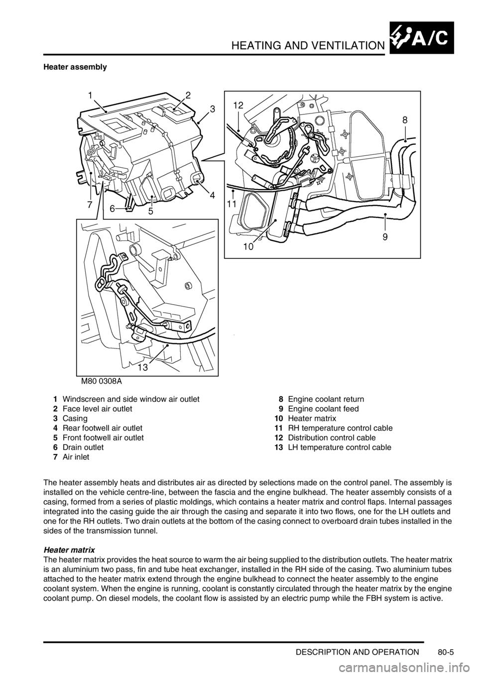
Heater assembly
1Windscreen and side window air outlet
2Face level air outlet
3Casing
4Rear footwell air outlet
5Front footwell air outlet
6Drain outlet
7Air inlet8Engine coolant return
9Engine coolant feed
10Heater matrix
11RH temperature control cable
12Distribution control cable
13LH temperature control cable
The heater assembly heats and distributes air as directed by selections made on the control panel. The assembly is
installed on the vehicle centre-line, between the fascia and the engine bulkhead. The heater assembly consists of a
casing, formed from a series of plastic moldings, which contains a heater matrix and control flaps. Internal passages
integrated into the casing guide the air through the casing and separate it into two flows, one for the LH outlets and
one for the RH outlets. Two drain outlets at the bottom of the casing connect to overboard drain tubes installed in the
sides of the transmission tunnel.
Heater matrix
The heater matrix provides the heat source to warm the air being supplied to the distribution outlets. The heater matrix
is an aluminium two pass, fin and tube heat exchanger, installed in the RH side of the casing. Two aluminium tubes
attached to the heater matrix extend through the engine bulkhead to connect the heater assembly to the engine
coolant system. When the engine is running, coolant is constantly circulated through the heater matrix by the engine
coolant pump. On diesel models, the coolant flow is assisted by an electric pump while the FBH system is active.
Page 1163 of 1529

HEATING AND VENTILATION
80-6DESCRIPTION AND OPERATION
Control flaps
Control flaps are installed in the heater assembly to control the temperature and distribution of air. Blend flaps control
the temperature and distribution flaps control the distribution.
Temperature and distribution control
Figure shows flaps set for medium heat to face level and footwell outlets
1Windscreen/Side windows outlet
2Heater assembly casing
3Air inlet
4Heater matrix5Front footwells outlet
6Rear footwells outlet
7Face level outlet
Blend flaps:Two sets of three blend flaps, one LH and one RH, regulate the flow of air through the heater matrix and
a heater matrix bypass, to control the temperature of the air leaving the heater assembly. The two sets of blend flaps
operate independently to allow different temperatures to be set for the LH and RH outlets.
Each blend flap is attached to a spindle. The end of each spindle extends through the side of the heater casing and
is attached to a common lever mechanism on the related side of the casing. A control cable is installed between the
lever mechanism and the related temperature knob on the control panel. When the flow is split between the bypass
and the heater matrix, the two flows mix downstream of the heater matrix to produce an even air temperature at the
individual outlets.
Distribution flaps: Separate distribution flaps are installed to control the flow of air to the footwells, windscreen/side
windows and the LH and RH face level outlets. The distribution flaps are attached to spindles that extend through the
RH side of the heater casing and are attached to a common lever mechanism. A control cable is installed between
the lever mechanism and the distribution knob on the control panel.