Page 989 of 1529

INTERIOR TRIM COMPONENTS
76-3-24 REPAIRS
Stowage pocket - front
$% 76.67.26
Remove
1.Remove access panel from front edge of front
stowage pocket.
2.Remove screw securing front stowage pocket
to headlining.
3.Remove lense from front interior lamp.
4.Remove 2 nuts securing front interior lamp to
headlining.
5.Disconnect multiplug from front interior lamp.
6.Remove front interior lamp.
7.Remove 10 screws securing front stowage
pocket to headlining.
8.Disconnect 3 multiplugs from sunroof
switches.
9.Remove front stowage pocket. 10.Release clips securing sunroof switch pack.
11.Remove switch pack.
Refit
1.Fit sunroof switch pack to front stowage pocket
and secure with clips.
2.Position front stowage pocket to headlining
and connect multiplugs to sunroof switches.
3.Fit and tighten 10 screws securing front
stowage pocket to headlining.
4.Connect multiplug to front interior lamp.
5.Fit front interior lamp to headlining and secure
with nuts.
6.Fit lense to front interior lamp.
7.Fit and tighten screw securing front of front
stowage pocket to headlining.
8.Fit access panel to front stowage pocket.
Page 1032 of 1529
SUNROOF
DESCRIPTION AND OPERATION 76-6-1
SUNROOF DESCRIPTION AND OPERAT ION
Electric sunroof component location
RHD shown, LHD similar
1Sunroof front switches
2Front sunroof motor and microswitch
3Rear sunroof - rear switch4Sunroof ECU
5BCU
Page 1033 of 1529
SUNROOF
76-6-2 DESCRIPTION AND OPERATION
Sunroof components
Page 1034 of 1529
SUNROOF
DESCRIPTION AND OPERATION 76-6-3
1Glass panel
2Nut - glass panel
3Frame - glass panel
4Bolt - glass panel
5Drive cables and lifting assembly
6Screw - glass panel frame
7Sunroof frame
8Sunroof blind
9Screw - sunroof frame10Drain tubes
11Screw - motor
12Motor and gearbox
13Spacer - manual sunroof regulator
14Regulator - manual sunroof
15Handle - manual sunroof
16Screw - manual sunroof regulator
17Screw - manual sunroof handle
Page 1035 of 1529
SUNROOF
76-6-4 DESCRIPTION AND OPERATION
System block diagram
1Passenger compartment fuse box
2BCU
3Sunroof ECU
4Front sunroof switch
5Front sunroof motor and microswitch6Rear sunroof - front switch
7Rear sunroof isolation switch
8Rear sunroof - rear switch
9Rear sunroof motor and microswitch
Page 1036 of 1529
SUNROOF
DESCRIPTION AND OPERATION 76-6-5
Description
General
The sunroof system consists of a front and a rear sunroof assembly. Both sunroof assemblies slide and tilt to open.
The sunroof system consists of the following components:
lSunroof ECU.
lBCU.
lFront sunroof switch.
lFront sunroof motor and microswitch.
lRear sunroof - front switch.
lRear sunroof - rear switch.
lRear sunroof isolation switch.
lRear sunroof motor and microswitch.
The BCU enables operation of the sunroof ECU. If the sunroof ECU does not receive an enable signal from the BCU,
neither sunroof assembly operates. The BCU is located behind the glovebox. The sunroof ECU is located above the
headlining next to the front sunroof assembly.
TestBook diagnoses the sunroof ECU.
Page 1037 of 1529
SUNROOF
76-6-6 DESCRIPTION AND OPERATION
Front sunroof switch
The front sunroof switch is located in the roof console above the windscreen in front of the front sunroof. It controls
the front sunroof motor via the sunroof ECU.
The front sunroof switch supplies an earth signal to the sunroof ECU. The pin at the ECU that receives the earth
signal determines whether ECU causes the sunroof to open or close.
TestBook cannot monitor the state of the front sunroof switch.
The following table lists the values which can be measured at the listed ECU pins when the conditions outlined are
met:
Signal values (connector connected)
Connector/Pin
No.Condition Resistance, ohms
C0784-2 Ignition in position II, front sunroof switch released > 10,000
C0784-2 Ignition in position II, front sunroof switch open < 0.5
C0785-7 Ignition in position II, front sunroof switch released > 10,000
C0785-7 Ignition in position II, front sunroof switch closed < 0.5
Page 1038 of 1529

SUNROOF
DESCRIPTION AND OPERATION 76-6-7
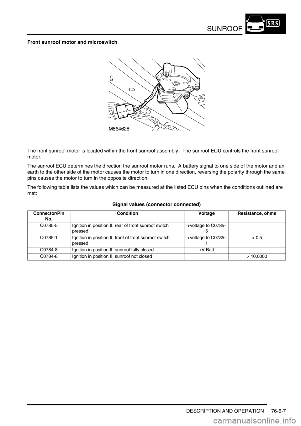
Front sunroof motor and microswitch
The front sunroof motor is located within the front sunroof assembly. The sunroof ECU controls the front sunroof
motor.
The sunroof ECU determines the direction the sunroof motor runs. A battery signal to one side of the motor and an
earth to the other side of the motor causes the motor to turn in one direction, reversing the polarity through the same
pins causes the motor to turn in the opposite direction.
The following table lists the values which can be measured at the listed ECU pins when the conditions outlined are
met:
Signal values (connector connected)
Connector/Pin
No.Condition Voltage Resistance, ohms
C0785-5 Ignition in position II, rear of front sunroof switch
pressed+voltage to C0785-
5
C0785-1 Ignition in position II, front of front sunroof switch
pressed+voltage to C0785-
1< 0.5
C0784-8 Ignition in position II, sunroof fully closed +V Batt
C0784-8 Ignition in position II, sunroof not closed > 10,0000