Page 1335 of 1529
ALARM SYSTEM AND HORN
86-4-12 DESCRIPTION AND OPERATION
Handset and receiver
The handset is incorporated in the key. It uses coded radio frequency signals to lock, unlock and super lock the vehicle
remotely with a range of up to 10 metres (33 ft). The handset also mobilises the vehicle by transmitting a
remobilisation signal when the handset is within range of the passive remobilisation exciter coil.
The receiver is located in front of the rear sunroof beneath the headlining. Signals transmitted by the handset are
distributed to the BCU via the receiver.
Input/Output
The BCU supplies the receiver with a 12 volts power supply. On receiving a valid signal from the handset, the receiver
transmits a 1000 baud signal to the BCU to allow locking/unlocking of the vehicle.
TestBook provides the ability to monitor the real time state of the remote receiver.
Page 1351 of 1529

ALARM SYSTEM AND HORN
86-4-28 REPAIR
Receiver - alarm system - models with
sunroof
$% 86.77.31
Remove
1.Remove trim seal from rear sunroof.
2.Release sunroof switch and remove screw
securing headlining.
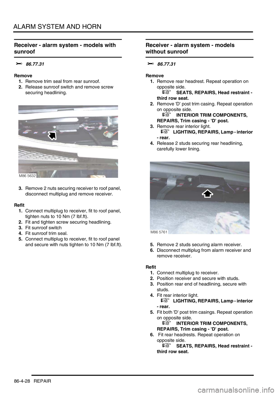
3.Remove 2 nuts securing receiver to roof panel,
disconnect multiplug and remove receiver.
Refit
1.Connect multiplug to receiver, fit to roof panel,
tighten nuts to 10 Nm (7 lbf.ft).
2.Fit and tighten screw securing headlining.
3.Fit sunroof switch
4.Fit sunroof trim seal.
5.Connect multiplug to receiver, fit to roof panel
and secure with nuts tighten to 10 Nm (7 lbf.ft).
Receiver - alarm system - models
without sunroof
$% 86.77.31
Remove
1.Remove rear headrest. Repeat operation on
opposite side.
+ SEATS, REPAIRS, Head restraint -
third row seat.
2.Remove 'D' post trim casing. Repeat operation
on opposite side.
+ INTERIOR TRIM COMPONENTS,
REPAIRS, Trim casing - 'D' post.
3.Remove rear interior light.
+ LIGHTING, REPAIRS, Lamp - interior
- rear.
4.Release 2 studs securing rear headlining,
carefully lower lining.
5.Remove 2 studs securing alarm receiver.
6.Disconnect multiplug from alarm receiver and
remove receiver.
Refit
1.Connect multiplug to receiver.
2.Position receiver and secure with studs.
3.Position rear end of headlining, secure with
studs.
4.Fit rear interior light.
+ LIGHTING, REPAIRS, Lamp - interior
- rear.
5.Fit both 'D' post trim casings. Repeat operation
on opposite side.
+ INTERIOR TRIM COMPONENTS,
REPAIRS, Trim casing - 'D' post.
6. Fit rear headrests. Repeat operation on
opposite side.
+ SEATS, REPAIRS, Head restraint -
third row seat.
M86 5632
M86 5761
Page 1384 of 1529

IN CAR ENTERTAINMENT
DESCRIPTION AND OPERATION 86-6-17
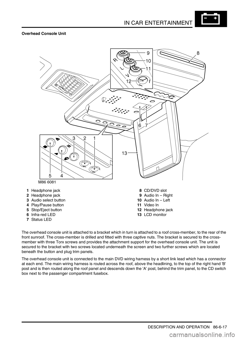
Overhead Console Unit
1Headphone jack
2Headphone jack
3Audio select button
4Play/Pause button
5Stop/Eject button
6Infra-red LED
7Status LED8CD/DVD slot
9Audio In – Right
10Audio In – Left
11Video In
12Headphone jack
13LCD monitor
The overhead console unit is attached to a bracket which in turn is attached to a roof cross-member, to the rear of the
front sunroof. The cross-member is drilled and fitted with three captive nuts. The bracket is secured to the cross-
member with three Torx screws and provides the attachment support for the overhead console unit. The unit is
secured to the bracket with two screws located underneath the screen and two further screws which are located
beneath the button and plug trim panels.
The overhead console unit is connected to the main DVD wiring harness by a short link lead which has a connector
at each end. The main wiring harness is routed across the roof, above the headlining, to the top of the right hand 'B'
post and is then routed along the roof panel and descends down the 'A' post, behind the trim panel, to the CD switch
box next to the passenger compartment fusebox.
Page 1407 of 1529
HARNESSES
86-7-2 REPAIRS
5.Release and disconnect 4 multiplugs from LH
lower 'A' post.
6.Release clip and disconnect rear washer pipe
from LH lower 'A' post.
7.Release harness from behind bonnet release
cable.
8.Release harness from 4 retainers in LH upper
'A' post and collect protective sleeves. 9.Release 4 clips securing harness to centre of
roof.
10.Disconnect multiplug from ACE accelerometer.
11.Disconnect multiplug from interior mirror.
12.Feed harness through roof to upper 'A' post.
13.Release 3 retainers securing harness to RH
roof panel.
14.Release 2 cable clips securing body harness to
sunroof harness.
Page 1412 of 1529

HARNESSES
REPAIRS 86-7-7
Refit
1.With assistance, position harness to air
conditioning ducting and secure with cable ties.
2.Secure harness to sunroof harness with cable
clips.
3.Connect multiplug to RF receiver.
4.Feed harness to LH and RH upper 'E' posts.
5.Feed harness through 'E' post to tail lamp and
rear bumper and secure with grommet.
6.Connect multiplug to fuel flap solenoid and
alarm sounder.
7.Position alarm sounder to rear quarter and
secure with nut to 9 Nm (7 lbf.ft).
8.Position both RH earth header to 'E' post and
tighten nut to 10 Nm (7 lbf.ft).
9.Feed tail door harness through 'E' post and
secure with grommet.
10.Position harness sleeve to outer edge of door
and pull harness through door.
11.Secure harness to tail door with clips.
12.Connect washer tube to rear of wiper arm.
13.Remove tape from draw string and secure to
CHMSL harness.
14.Draw harness through tail door and connect
Lucars to CHMSL.
15.Fit CHMSL cover and secure with screws.
16.Connect multiplug to door lock switch.
17.Connect Lucars to HRW.
18.Connect multiplug to rear wiper motor.
19.Connect multiplug to door latch.
20.Fit plastic sheet to tail door, ensuring it aligns
with witness marks.
21.Fit tail door trim casing.
+ DOORS, REPAIRS, Trim casing - tail
door.
22.Connect Lucar to radio aerial RH amplifier.
23.Secure harness to RH side of body with clips
and retainers.
24.Position both LH earth header to 'E' post and
tighten nut to 10 Nm (7 lbf.ft).
25.Connect multiplugs to both tail/flasher lamps
and secure harness to bumper with clips.
26.Fit both rear tail lamps.
+ LIGHTING, REPAIRS, Lamp - tail.
27.Secure harness to rear LH side of body with 6
cable clips.
28.Connect 2 Lucars to rear air conditioning unit.
29.Fit both luggage compartment trim casings.
+ INTERIOR TRIM COMPONENTS,
REPAIRS, Trim casing - side - loadspace.
30.Feed harness into position for rear interior light.
31.Connect Lucar to radio aerial LH amplifier.
32.Secure harness to body with cable ties clips
and retainers.
33.Secure air conditioning ducting to body with
rivets.
34.Feed harness to LH lower 'A' post. 35.Secure harness to LH side of body with cable
tie clips and retainers.
36.Connect and secure multiplugs to lower LH 'A'
post.
37.Feed harness through roof to centre.
38.Secure harness behind bonnet release cable.
39.Connect rear washer pipe at lower 'A' post and
secure with clip.
40.Secure harness to roof with clips.
41.Connect multiplug to interior mirror, ARC
accelerometer.
42.Position sound deadening panels and secure
with clips.
43.Fit headlining.
+ INTERIOR TRIM COMPONENTS,
REPAIRS, Headlining.
44.Fit fascia panel.
+ INTERIOR TRIM COMPONENTS,
REPAIRS, Fascia.