1999 LAND ROVER DISCOVERY navigation system
[x] Cancel search: navigation systemPage 1460 of 1529
NAVIGATION SYSTEM
DESCRIPTION AND OPERATION 87-7
Calibration
Calibration is required after initial installation or replacement of the navigation computer. It may also be necessary
after repairs to system wiring and if route navigation becomes inaccurate or fails to operate. If the navigation computer
contains an existing calibration, this must be deleted, using the garage menu, prior to running the new calibration
routine. The sensor inputs should also be checked before running the calibration routine.
Sensor Check
1Call up the SENSORS screen on the LCD:
lIf the navigation CD-ROM has not been installed before, press and hold multifunction button 1 then press
multifunction button 10.
lIf the navigation CD-ROM has been installed before, use the garage menu as detailed above.
2Drive the vehicle forwards a short distance at a speed greater than 2.5 mph (4 km/h) and ensure the road speed
counter on the SENSORS screen starts to increment.
3Select reverse gear and ensure the direction arrows on the SENSORS screen point rearwards.
4Ensure the GPS data on the SENSORS screen is displayed and updated.
NOTE: The GPS data will randomly display a GPS MODULE FAILURE message. This is not a fault condition, and
no action need be taken, provided the GPS data switches between the GPS MODULE FAILURE message and
actual GPS data.
5Exit the SENSORS screen:
lIf the navigation CD-ROM has not been installed before, press and hold multifunction button 1 then press
multifunction button 10.
lIf the navigation CD-ROM has been installed before, press the Nav button.
Page 1461 of 1529
NAVIGATION SYSTEM
87-8 DESCRIPTION AND OPERATION
Calibration Routine
1Park the vehicle outside in an area clear of high buildings, trees etc.
NOTE: The more open the surrounding area is, the faster the system will acquire sufficient GPS satellite signals to
begin calibration. To minimise the calibration time, the vehicle should not be moved again until the calibration
ride.
2Turn the ignition switch to position II. If the navigation computer does not come on, press the navigation
computer ON button.
3If necessary, use the navigation computer multifunction buttons to enter the security code.
4Turn the ignition switch to position 0 and remove the ignition key.
5Press the navigation computer ON button.
6Call up the SENSORS screen on the LCD:
lIf the navigation CD-ROM has not been installed before, press and hold multifunction button 1 then press
multifunction button 10.
lIf the navigation CD-ROM has been installed before, use the garage menu as detailed above.
7Turn the LH rotary control to minimum volume.
8Wait for 30 minutes. If necessary, the vehicle can be left unattended and locked.
NOTE: Land Rover recommend a minimum of 30 minutes be allowed to elapse in order to ensure that only a short
distance need be driven to achieve calibration.
9After the 30 minutes have elapsed, ensure the navigation computer LCD shows a GPS almanac figure of 27 or
higher.
10Start the vehicle engine and allow to idle.
11Install the navigation CD-ROM.
12Wait until the navigation computer LCD prompts for a language to be selected. Turn the RH rotary control to
scroll through the options, highlight the required language and press the RH rotary control to select.
13The navigation computer LCD will prompt for a voice to be selected. Turn the RH rotary control to scroll through
the options, highlight the required voice and press the RH rotary control to select.
14Wait until the navigation computer LCD advises "language has been loaded OK". Press the RH rotary control to
confirm the language and voice selections.
15The navigation computer LCD will default to the CALIBRATION RIDE screen and should show the
CALIBRATION RIDE CAN START message. The GPS data and the road speed counter will also be shown.
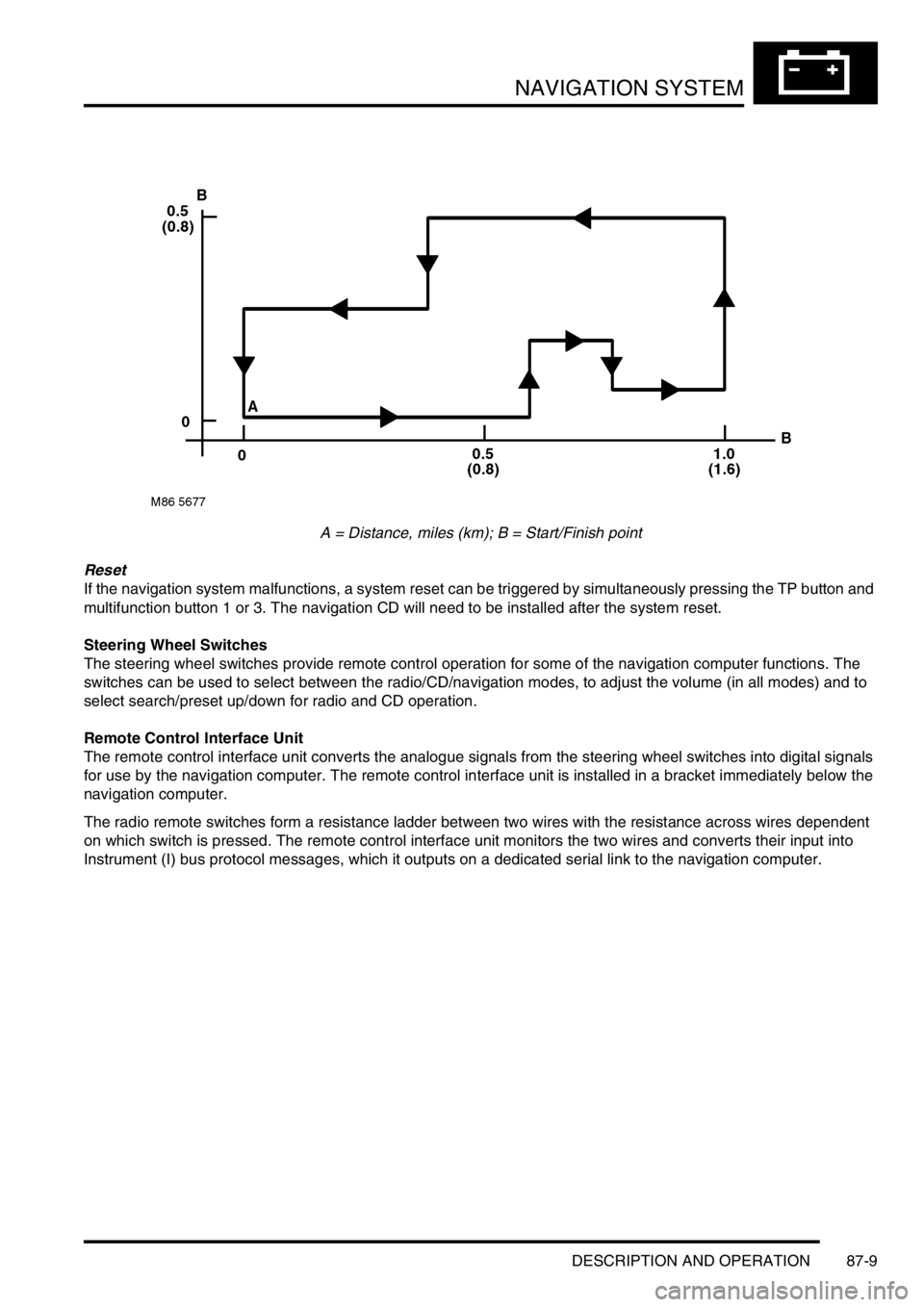
16Drive the vehicle over a road route approximating that shown below (it is not necessary to copy the route
exactly). Calibration is complete when the navigation computer LCD switches to show DESTINATION & POI
and the satellite graphic. If all the pre calibration ride conditions were complied with, calibration is typically
achieved within 3 miles (5 km) and usually occurs when the vehicle returns to the start point. However,
calibration may be achieved earlier in the journey and, if it is, there is no need to complete the remainder of the
calibration route.
17After calibration is achieved, return to the dealership, park the vehicle and stop the engine.
18Turn the ignition switch to position I.
19Use the system settings menu to set the navigation computer to local time and the required units of measure:
aPress the Nav button.
bTurn the RH rotary control to scroll through the displayed menu, highlight TIME and press the RH rotary
control to select. Press the + or – multifunction button to adjust the time in 30 minute steps. Select the 24
hour clock and confirm by pressing the OK multifunction button.
cIf metric units of measure are required, go to step e) (the navigation computer defaults to metric units of
measure).
dIf Imperial units of measure are required, turn the RH rotary control to scroll through the displayed menu,
highlight MEASURING UNIT and press the RH rotary control to select. Turn the RH rotary control to
highlight IMPERIAL and press the RH rotary control to select.
ePress the Nav button to return to the destination menu.
20Calibration is complete. The navigation system is ready for use.
NOTE: The accuracy of the system will automatically be fine tuned when a further journey is made, but this is not
required as part of the calibration procedure.
NOTE: In European countries, the territory will have to be set the first time the navigation system is used, and the
first time a destination in another country is selected. The first time the navigation system is used or a destination
in another country is selected, a map is displayed with the default/current territory highlighted. To change the
territory: Press the RH rotary control to display the territory list; turn the RH rotary control to scroll through the
list and highlight the required territory; press the RH rotary control to confirm the selection.
Page 1462 of 1529
NAVIGATION SYSTEM
DESCRIPTION AND OPERATION 87-9
A = Distance, miles (km); B = Start/Finish point
Reset
If the navigation system malfunctions, a system reset can be triggered by simultaneously pressing the TP button and
multifunction button 1 or 3. The navigation CD will need to be installed after the system reset.
Steering Wheel Switches
The steering wheel switches provide remote control operation for some of the navigation computer functions. The
switches can be used to select between the radio/CD/navigation modes, to adjust the volume (in all modes) and to
select search/preset up/down for radio and CD operation.
Remote Control Interface Unit
The remote control interface unit converts the analogue signals from the steering wheel switches into digital signals
for use by the navigation computer. The remote control interface unit is installed in a bracket immediately below the
navigation computer.
The radio remote switches form a resistance ladder between two wires with the resistance across wires dependent
on which switch is pressed. The remote control interface unit monitors the two wires and converts their input into
Instrument (I) bus protocol messages, which it outputs on a dedicated serial link to the navigation computer.
Page 1464 of 1529

NAVIGATION SYSTEM
DESCRIPTION AND OPERATION 87-11
Deze pagina werd opzettelijk niet gebruikt
Cette page est intentionnellement vierge
Questa pagina è stata lasciata in bianco di proposito Diese Seite ist leer
Esta página foi deixada intencionalmente em branco
Esta página fue dejada en blanco intencionalmente This page is intentionally left blank
DESCRIPTION AND OPERAT ION
Page 1465 of 1529
NAVIGATION SYSTEM
87-12 DESCRIPTION AND OPERATION
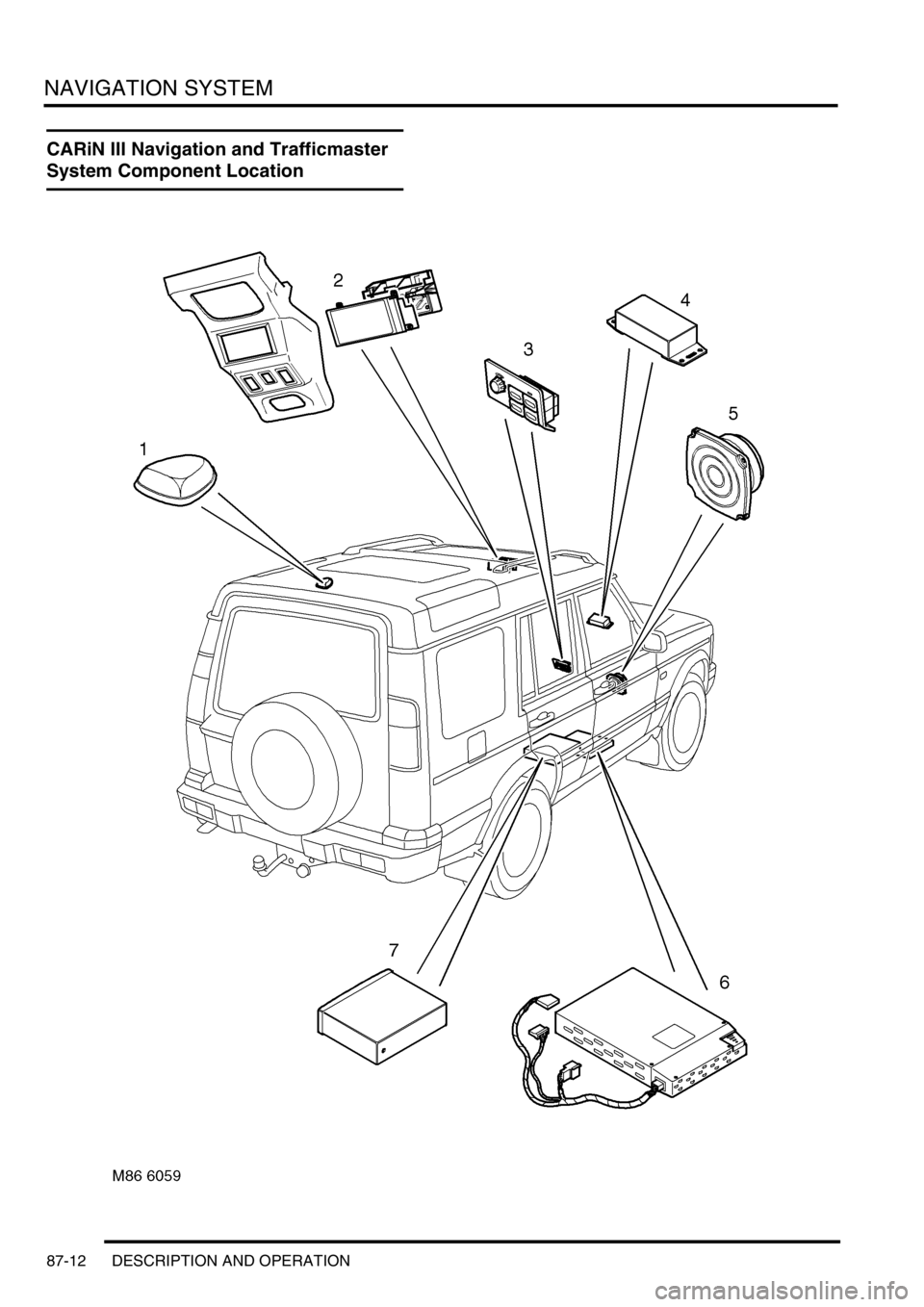
CARiN III Navigation and Trafficmaster
System Component Location
Page 1466 of 1529

NAVIGATION SYSTEM
DESCRIPTION AND OPERATION 87-13
1GPS antenna
2Display unit
3Switch pack
4Trafficmaster antenna
5Navigation speaker
6Trafficmaster monitor unit
7Navigation computer
Page 1467 of 1529

NAVIGATION SYSTEM
87-14 DESCRIPTION AND OPERATION
Description
General
Where fitted, the CARiN III and Trafficmaster system combines a satellite navigation system (CARiN III) with a real-
time traffic information system (Trafficmaster).
The satellite navigation system provides computer generated audible and visual route guidance information to enable
the driver to reach a desired destination. The system allows the driver to choose between road navigation and off-
road navigation, and to incorporate waypoints. Road navigation also allows the driver to choose between using minor
or major roads and the quickest or shortest route. Directions to hospitals, museums, monuments, hotels etc. are also
available. The computer uses map information stored on a CD-ROM to determine the best route for the journey and
provide the driver with details of directions and approaching junctions. The current position of the vehicle is
determined using a combination of vehicle sensor inputs and the Global Positioning System (GPS).
The Trafficmaster system displays live traffic flow information on the road navigation map screens. Traffic speed is
indicated on the maps by colour coded roads and arrows. The traffic flow information is relayed from a network of
sensors covering motorways and trunk roads. Data from the sensors is updated on a three minute cycle, 24 hours a
day, 365 days a year.
The navigation system consists of the following components:
lNavigation computer
lGPS antenna
lDisplay unit
lSwitch pack
lNavigation speaker
lTrafficmaster monitor ECU
lTrafficmaster antenna
Navigation Computer
The navigation computer is located in a bracket under the RH front seat, immediately behind the CD autochanger.
The navigation computer contains all the hardware and software required for control of the navigation system,
including the GPS receiver and a solid state piezo gyro. Using the gyro, and inputs from the GPS antenna and the
vehicle K bus, the navigation computer determines the vehicle’s current position, direction and speed.
The navigation computer also houses a CD-ROM drive. The drive is used to read map data from country specific CD’s
and also to load software into the computer. A button, adjacent to the CD slot, is provided to eject the CD from the
unit. If the ignition is on, one press of the button will eject the CD. If the ignition is off, two presses are required, one
to wake up the system and the second to eject the CD. Access to the CD-ROM drive is from the rear of the RH front
seat.
Page 1468 of 1529
NAVIGATION SYSTEM
DESCRIPTION AND OPERATION 87-15
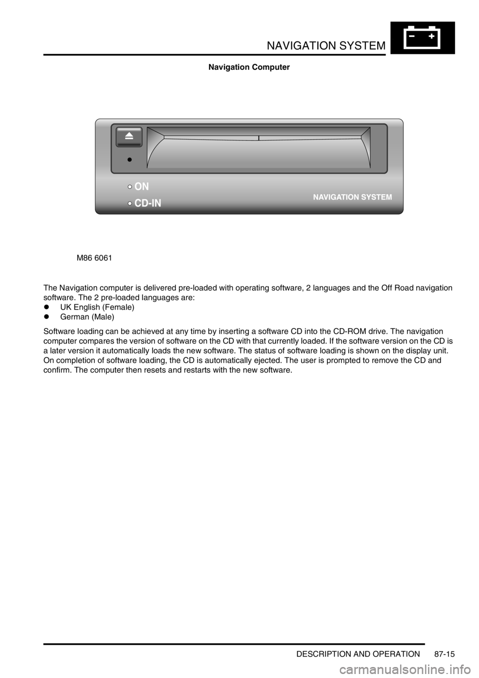
Navigation Computer
The Navigation computer is delivered pre-loaded with operating software, 2 languages and the Off Road navigation
software. The 2 pre-loaded languages are:
lUK English (Female)
lGerman (Male)
Software loading can be achieved at any time by inserting a software CD into the CD-ROM drive. The navigation
computer compares the version of software on the CD with that currently loaded. If the software version on the CD is
a later version it automatically loads the new software. The status of software loading is shown on the display unit.
On completion of software loading, the CD is automatically ejected. The user is prompted to remove the CD and
confirm. The computer then resets and restarts with the new software.
M86 6061
ON
CD-IN