Page 1469 of 1529
NAVIGATION SYSTEM
87-16 DESCRIPTION AND OPERATION
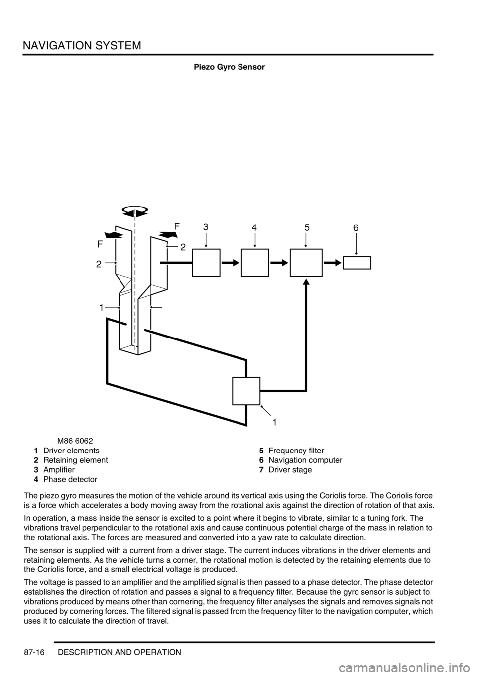
Piezo Gyro Sensor
1Driver elements
2Retaining element
3Amplifier
4Phase detector5Frequency filter
6Navigation computer
7Driver stage
The piezo gyro measures the motion of the vehicle around its vertical axis using the Coriolis force. The Coriolis force
is a force which accelerates a body moving away from the rotational axis against the direction of rotation of that axis.
In operation, a mass inside the sensor is excited to a point where it begins to vibrate, similar to a tuning fork. The
vibrations travel perpendicular to the rotational axis and cause continuous potential charge of the mass in relation to
the rotational axis. The forces are measured and converted into a yaw rate to calculate direction.
The sensor is supplied with a current from a driver stage. The current induces vibrations in the driver elements and
retaining elements. As the vehicle turns a corner, the rotational motion is detected by the retaining elements due to
the Coriolis force, and a small electrical voltage is produced.
The voltage is passed to an amplifier and the amplified signal is then passed to a phase detector. The phase detector
establishes the direction of rotation and passes a signal to a frequency filter. Because the gyro sensor is subject to
vibrations produced by means other than cornering, the frequency filter analyses the signals and removes signals not
produced by cornering forces. The filtered signal is passed from the frequency filter to the navigation computer, which
uses it to calculate the direction of travel.
Page 1470 of 1529
NAVIGATION SYSTEM
DESCRIPTION AND OPERATION 87-17
GPS Antenna
The GPS antenna is installed on the rear of the roof, on the vehicle centreline. A diplexer unit on the underside of the
GPS antenna amplifies the radio signals received from the GPS satellites and transmits them through a co-axial cable
to the navigation computer for processing.
Display Unit
The display unit is integrated into the front stowage pocket, above the rear view mirror. The display unit is a colour
Liquid Crystal Display (LCD) that shows the programming menus, route guidance and traffic information. The display
illumination level automatically dims for night time viewing when the exterior lights are switched on.
Page 1471 of 1529
NAVIGATION SYSTEM
87-18 DESCRIPTION AND OPERATION
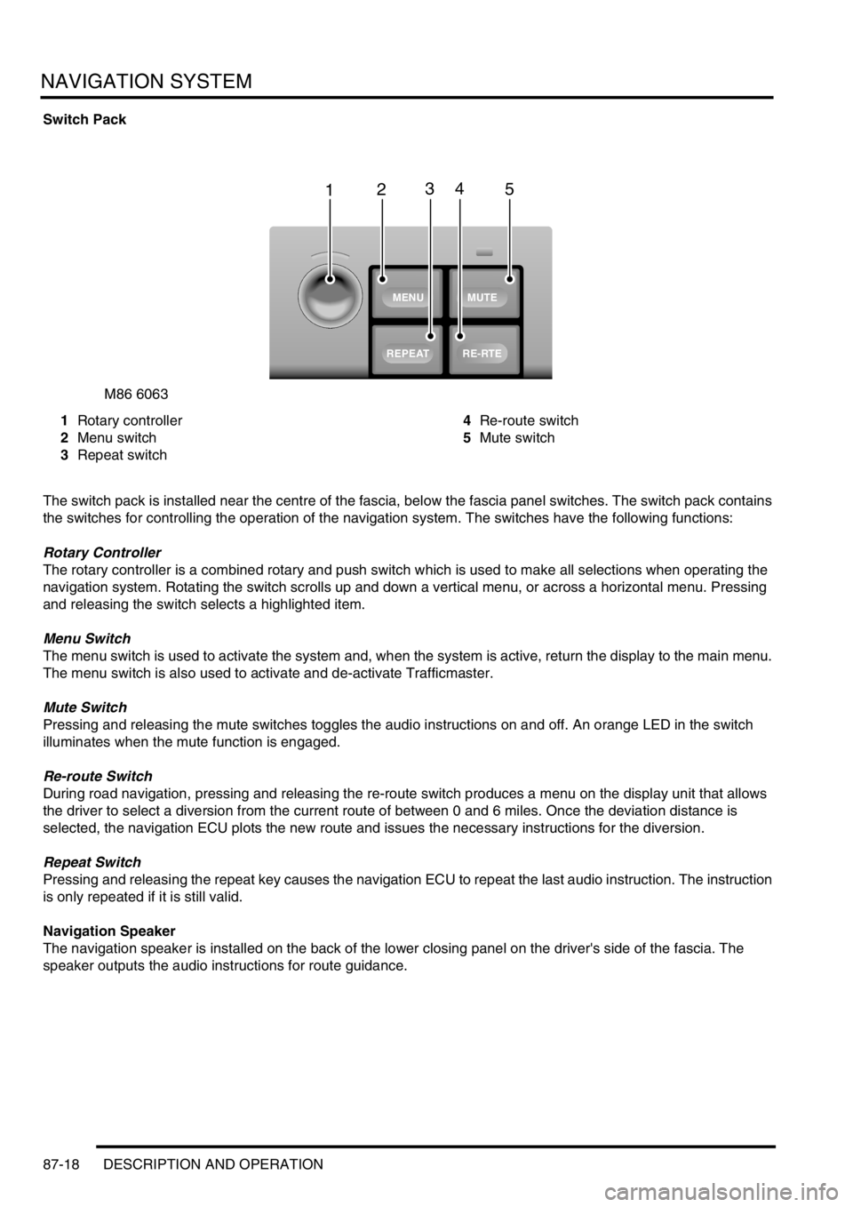
Switch Pack
1Rotary controller
2Menu switch
3Repeat switch4Re-route switch
5Mute switch
The switch pack is installed near the centre of the fascia, below the fascia panel switches. The switch pack contains
the switches for controlling the operation of the navigation system. The switches have the following functions:
Rotary Controller
The rotary controller is a combined rotary and push switch which is used to make all selections when operating the
navigation system. Rotating the switch scrolls up and down a vertical menu, or across a horizontal menu. Pressing
and releasing the switch selects a highlighted item.
Menu Switch
The menu switch is used to activate the system and, when the system is active, return the display to the main menu.
The menu switch is also used to activate and de-activate Trafficmaster.
Mute Switch
Pressing and releasing the mute switches toggles the audio instructions on and off. An orange LED in the switch
illuminates when the mute function is engaged.
Re-route Switch
During road navigation, pressing and releasing the re-route switch produces a menu on the display unit that allows
the driver to select a diversion from the current route of between 0 and 6 miles. Once the deviation distance is
selected, the navigation ECU plots the new route and issues the necessary instructions for the diversion.
Repeat Switch
Pressing and releasing the repeat key causes the navigation ECU to repeat the last audio instruction. The instruction
is only repeated if it is still valid.
Navigation Speaker
The navigation speaker is installed on the back of the lower closing panel on the driver's side of the fascia. The
speaker outputs the audio instructions for route guidance.
M86 6063
1
MUTE
RE-RTE
REPEAT
MENU
2345
Page 1472 of 1529
NAVIGATION SYSTEM
DESCRIPTION AND OPERATION 87-19
Trafficmaster Monitor ECU
The Trafficmaster monitor ECU is installed underneath the CD autochanger, below the RH front seat. The
Trafficmaster monitor ECU processes the traffic flow data from the Trafficmaster antenna and combines it with data
from the navigation computer to display on the display unit.
Trafficmaster Antenna
The Trafficmaster antenna is installed in the fascia, on the rear of the instrument pack. The antenna receives radio
signals containing the data relayed from the traffic flow sensors, and transmits the information on a hardwired
connection to the Trafficmaster monitor ECU.
Page 1473 of 1529
NAVIGATION SYSTEM
87-20 DESCRIPTION AND OPERATION
Operation
General
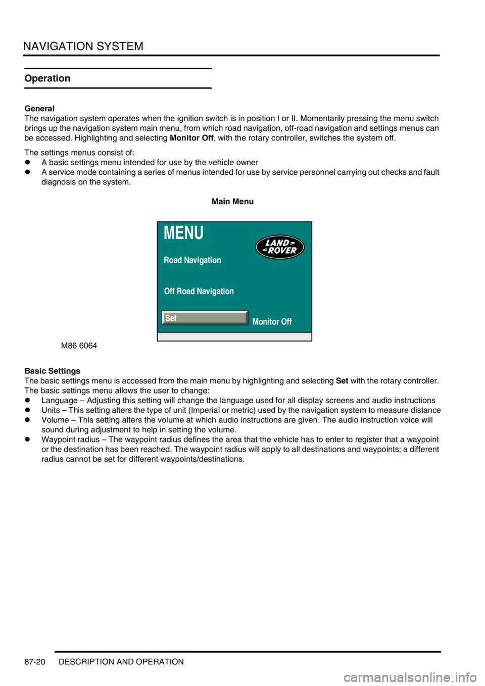
The navigation system operates when the ignition switch is in position I or II. Momentarily pressing the menu switch
brings up the navigation system main menu, from which road navigation, off-road navigation and settings menus can
be accessed. Highlighting and selecting Monitor Off, with the rotary controller, switches the system off.
The settings menus consist of:
lA basic settings menu intended for use by the vehicle owner
lA service mode containing a series of menus intended for use by service personnel carrying out checks and fault
diagnosis on the system.
Main Menu
Basic Settings
The basic settings menu is accessed from the main menu by highlighting and selecting Set with the rotary controller.
The basic settings menu allows the user to change:
lLanguage – Adjusting this setting will change the language used for all display screens and audio instructions
lUnits – This setting alters the type of unit (Imperial or metric) used by the navigation system to measure distance
lVolume – This setting alters the volume at which audio instructions are given. The audio instruction voice will
sound during adjustment to help in setting the volume.
lWaypoint radius – The waypoint radius defines the area that the vehicle has to enter to register that a waypoint
or the destination has been reached. The waypoint radius will apply to all destinations and waypoints; a different
radius cannot be set for different waypoints/destinations.
MENU
Road Navigation
Off Road Navigation
Monitor Off
M86 6064
Set
Page 1474 of 1529
NAVIGATION SYSTEM
DESCRIPTION AND OPERATION 87-21
Basic Settings Menu
Service Mode
The service mode is accessed from the basic settings menu, by pushing and holding the menu switch until the service
mode menu is displayed. On the service mode menu, various checks can be selected using the rotary controller.
Pushing the menu switch again returns the system to the main menu.
The service mode has four main functions:
lTo check that components are fitted and to determine their hardware/software levels
lTo perform a quick 'health check' of the major input signals to the system
lTo check for correct operation of the control switches
lTo check the status of the GPS reception.
Service Mode Menu
SET
Units Language
D
km
110y 220y 550ymilesGB Other
Volume
Wp. radius
- 2
M86 6065
M86 6066
ON-BOARD MONITOR
NAVIGATION / GRAPHIC
ELEMENT
VIDEO MODULE
GPS
Service Mode
SENSOR TEST
Page 1475 of 1529
NAVIGATION SYSTEM
87-22 DESCRIPTION AND OPERATION
On-Board Monitor (Display Unit)
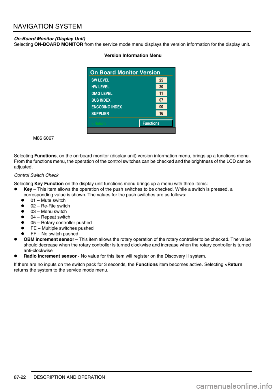
Selecting ON-BOARD MONITOR from the service mode menu displays the version information for the display unit.
Version Information Menu
Selecting Functions, on the on-board monitor (display unit) version information menu, brings up a functions menu.
From the functions menu, the operation of the control switches can be checked and the brightness of the LCD can be
adjusted.
Control Switch Check
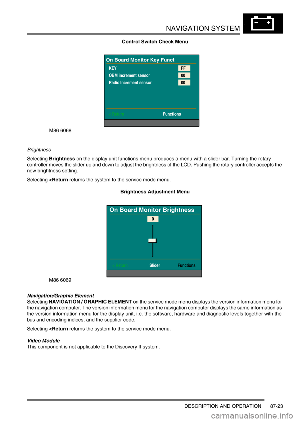
Selecting Key Function on the display unit functions menu brings up a menu with three items:
lKey – This item allows the operation of the push switches to be checked. While a switch is pressed, a
corresponding value is shown. The values for the push switches are as follows:
l01 – Mute switch
l02 – Re-Rte switch
l03 – Menu switch
l04 – Repeat switch
l05 – Rotary controller pushed
lFE – Multiple switches pushed
lFF – No switch pushed
lOBM increment sensor – This item allows the rotary operation of the rotary controller to be checked. The value
should decrease when the rotary controller is turned clockwise and increase when the rotary controller is turned
anti-clockwise
lRadio increment sensor - No value for this item will register on the Discovery II system.
If there are no inputs on the switch pack for 3 seconds, the Functions item becomes active. Selecting
returns the system to the service mode menu.
M86 6067
On Board Monitor Version
SW LEVEL
HW LEVEL
DIAG LEVEL
BUS INDEX
ENCODING INDEX
SUPPLIER
< Return25
20
11
07
00
16
Functions
Page 1476 of 1529
NAVIGATION SYSTEM
DESCRIPTION AND OPERATION 87-23
Control Switch Check Menu
Brightness
Selecting Brightness on the display unit functions menu produces a menu with a slider bar. Turning the rotary
controller moves the slider up and down to adjust the brightness of the LCD. Pushing the rotary controller accepts the
new brightness setting.
Selecting
Brightness Adjustment Menu
Navigation/Graphic Element
Selecting NAVIGATION / GRAPHIC ELEMENT on the service mode menu displays the version information menu for
the navigation computer. The version information menu for the navigation computer displays the same information as
the version information menu for the display unit, i.e. the software, hardware and diagnostic levels together with the
bus and encoding indices, and the supplier code.
Selecting
Video Module
This component is not applicable to the Discovery II system.
M86 6068
On Board Monitor Key Funct
KEY
OBM increment sensor
Radio Increment sensor
< ReturnFF
00
00
Functions
M86 6069
On Board Monitor Brightness
< Return SliderFunctions
0