Page 1140 of 1529

CORROSION PREVENTION AND SEALING
CORROSION PREVENTION 77-4-7
The checks described above are intended to be visual only. It is not intended that the operator should remove trim
panels, finishers, rubbing strips or sound-deadening materials when checking the vehicle for corrosion and paint
damage.
With the vehicle on a lift, and using an inspection or spot lamp, visually check for the following:
lCorrosion damage and damaged paintwork, condition of underbody sealer on front and rear lower panels, sills
and wheel arches;
lDamage to underbody sealer. Corrosion in areas adjacent to suspension mountings and fuel tank fixings.
NOTE: The presence of small blisters in the underbody sealer is acceptable, providing they do not expose bare metal.
Pay special attention to signs of damage caused to panels or corrosion protection material by incorrect jack
positioning.
WARNING: It is essential to follow the correct jacking and lifting procedures.
With the vehicle lowered, visually check for evidence of damage and corrosion on all visible painted areas, in
particular the following:
lFront edge of bonnet;
lVisible flanges in engine compartment;
lLower body and door panels.
Rectify any bodywork damage or evidence of corrosion found during inspection as soon as is practicable, both to
minimise the extent of the damage and to ensure the long term effectiveness of the factory-applied corrosion
prevention treatment. Where the cost of rectification work is the owner's responsibility, the Dealer must advise the
owner and endorse the relevant documentation accordingly.
Where corrosion has become evident and is emanating from beneath a removable component (e.g. trim panel,
window glass, seat etc.), remove the component as required to permit effective rectification.
Underbody protection repairs
Whenever body repairs are carried out, ensure that full sealing and corrosion protection treatments are reinstated.
This applies both to the damaged areas and also to areas where protection has been indirectly impaired, as a result
either of accident damage or repair operations.
Remove corrosion protection from the damaged area before straightening or panel beating. This applies in particular
to panels coated with wax, PVC underbody sealer, sound deadening pads etc.
WARNING: DO NOT use oxy-acetylene gas equipment to remove corrosion prevention materials. Large
volumes of fumes and gases are liberated by these materials when they burn.
NOTE: Equipment for the removal of tough anti-corrosion sealers offers varying degrees of speed and effectiveness.
The compressed air-operated scraper (NOT an air chisel) offers a relatively quiet mechanical method using an
extremely rapid reciprocating action. Move the operating end of the tool along the work surface to remove the material.
The most common method of removal is by means of a hot air blower with integral scraper.
Another tool, and one of the most efficient methods, is the rapid-cutting 'hot knife'. This tool uses a wide blade and is
quick and versatile, able to be used easily in profiled sections where access is otherwise difficult.
Use the following procedure when repairing underbody coatings:
1Remove existing underbody coatings
2After panel repair, clean the affected area with a solvent wipe, and treat bare metal with an etch phosphate
material
3Re-prime the affected area
CAUTION: DO NOT, under any circumstances, apply underbody sealer directly to bare metal surfaces.
4Replace all heat-fusible plugs which have been disturbed. Where such plugs are not available use rubber
grommets of equivalent size, ensuring that they are embedded in sealer
5Mask off all mounting faces from which mechanical components, hoses and pipe clips, have been removed.
Underbody sealer must be applied before such components are refitted
6Brush sealer into all exposed seams
7Spray the affected area with an approved service underbody sealer
8Remove masking from component mounting faces, and touch-in where necessary. Allow adequate drying time
before applying underbody wax
Page 1176 of 1529

HEATING AND VENTILATION
REPAIRS 80-19
Servo - air distribution control
$% 80.10.30
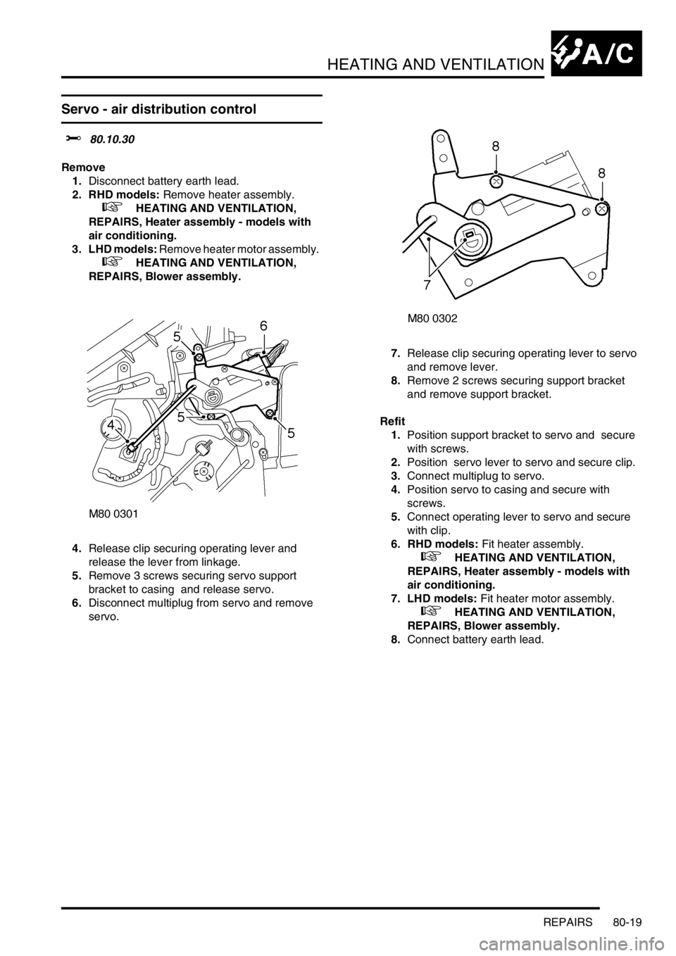
Remove
1.Disconnect battery earth lead.
2. RHD models: Remove heater assembly.
+ HEATING AND VENTILATION,
REPAIRS, Heater assembly - models with
air conditioning.
3. LHD models: Remove heater motor assembly.
+ HEATING AND VENTILATION,
REPAIRS, Blower assembly.
4.Release clip securing operating lever and
release the lever from linkage.
5.Remove 3 screws securing servo support
bracket to casing and release servo.
6.Disconnect multiplug from servo and remove
servo. 7.Release clip securing operating lever to servo
and remove lever.
8.Remove 2 screws securing support bracket
and remove support bracket.
Refit
1.Position support bracket to servo and secure
with screws.
2.Position servo lever to servo and secure clip.
3.Connect multiplug to servo.
4.Position servo to casing and secure with
screws.
5.Connect operating lever to servo and secure
with clip.
6. RHD models: Fit heater assembly.
+ HEATING AND VENTILATION,
REPAIRS, Heater assembly - models with
air conditioning.
7. LHD models: Fit heater motor assembly.
+ HEATING AND VENTILATION,
REPAIRS, Blower assembly.
8.Connect battery earth lead.
Page 1177 of 1529
HEATING AND VENTILATION
80-20REPAIRS
Servo - air temperature control
$% 80.10.42
Remove
1.Disconnect battery earth lead.
2. Driver side: Remove heater assembly.
+ HEATING AND VENTILATION,
REPAIRS, Heater assembly - models with
air conditioning.
3. Passenger side: Remove blower assembly.
+ HEATING AND VENTILATION,
REPAIRS, Blower assembly.
4.Disconnect multiplug from servo.
5.Remove 3 screws securing servo to casing and
release servo.
6.Release clip securing operating lever, release
the lever and remove servo. lever. Refit
1.Connect operating lever to servo and secure
with clip.
2.Position servo to casing, engage locating pegs
and secure with screws.
3.Connect multiplug to servo.
4. Driver side: Fit heater assembly.
+ HEATING AND VENTILATION,
REPAIRS, Heater assembly - models with
air conditioning.
5. Passenger side: Fit blower assembly.
+ HEATING AND VENTILATION,
REPAIRS, Blower assembly.
6.Connect battery earth lead.
Page 1179 of 1529
HEATING AND VENTILATION
80-22REPAIRS
Heater assembly - models without air
conditioning
$% 80.20.01.99
Remove
1.Drain cooling system.
l
+ COOLING SYSTEM - Td5,
ADJUSTMENTS, Drain and refill.
l
+ COOLING SYSTEM - V8,
ADJUSTMENTS, Drain and refill.
2. Diesel models: Remove 3 bolts and remove
engine cover.
3.Release clips and disconnect coolant hoses
from heater pipes.
CAUTION: Always fit plugs to open
connections to prevent contamination.
4.Remove facia assembly.
+ INTERIOR TRIM COMPONENTS,
REPAIRS, Fascia.5.Disconnect harness multiplug from heater
blower motor.
6.Remove bolt and 2 nuts securing heater
blower housing assembly to body and remove
blower.
7.Disconnect 2 drain tubes from base of heater.
Page 1181 of 1529
HEATING AND VENTILATION
80-24REPAIRS
Heater assembly - models with air
conditioning
$% 80.20.01.98
Remove
1.Drain cooling system.
l
+ COOLING SYSTEM - V8,
ADJUSTMENTS, Drain and refill.
l
+ COOLING SYSTEM - Td5,
ADJUSTMENTS, Drain and refill.
2.Evacuate air conditioning system.
+ AIR CONDITIONING, REFRIGERANT
RECOVERY, RECYCLING AND
RECHARGING, Refrigerant recovery,
recycling and recharging.
3.Release 2 clips securing heater hoses to
heater and release hoses.
4.Remove 2 bolts securing air conditioning pipes
to evaporator, release pipes and discard 'O'
rings.
CAUTION: Always fit plugs to open
connections to prevent contamination.
5.Remove fascia.
+ INTERIOR TRIM COMPONENTS,
REPAIRS, Fascia.6.Remove screws securing rear heater ducting
and remove ducting.
7.Disconnect multiplug from heater motor.
8.Remove 2 nuts and bolt securing heater motor
assembly and remove motor assembly from
heater casing.
Page 1182 of 1529

HEATING AND VENTILATION
REPAIRS 80-25
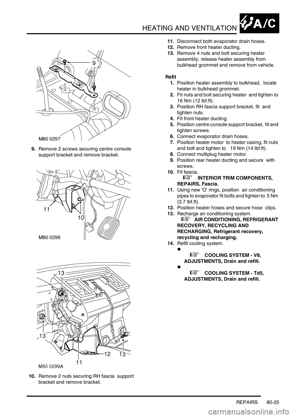
9.Remove 2 screws securing centre console
support bracket and remove bracket.
10.Remove 2 nuts securing RH fascia support
bracket and remove bracket. 11.Disconnect both evaporator drain hoses.
12.Remove front heater ducting.
13.Remove 4 nuts and bolt securing heater
assembly, release heater assembly from
bulkhead grommet and remove from vehicle.
Refit
1.Position heater assembly to bulkhead, locate
heater in bulkhead grommet.
2.Fit nuts and bolt securing heater and tighten to
16 Nm (12 lbf.ft).
3.Position RH fascia support bracket, fit and
tighten nuts.
4.Fit front heater ducting.
5.Position centre console support bracket, fit and
tighten screws.
6.Connect evaporator drain hoses.
7.Position heater motor to heater casing, fit nuts
and bolt and tighten to 19 Nm (14 lbf.ft).
8.Connect multiplug heater motor.
9.Position rear heater ducting and secure with
screws.
10.Fit fascia.
+ INTERIOR TRIM COMPONENTS,
REPAIRS, Fascia.
11.Using new 'O' rings, position air conditioning
pipes to evaporator fit bolts and tighten to 5 Nm
(3.7 lbf.ft).
12.Position heater hoses and secure hose clips.
13.Recharge air conditioning system.
+ AIR CONDITIONING, REFRIGERANT
RECOVERY, RECYCLING AND
RECHARGING, Refrigerant recovery,
recycling and recharging.
14.Refill cooling system.
l
+ COOLING SYSTEM - V8,
ADJUSTMENTS, Drain and refill.
l
+ COOLING SYSTEM - Td5,
ADJUSTMENTS, Drain and refill.
Page 1186 of 1529

HEATING AND VENTILATION
REPAIRS 80-29
Heater matrix
$% 80.20.29
Remove
1.Remove heater assembly.
+ HEATING AND VENTILATION,
REPAIRS, Heater assembly - models with
air conditioning.
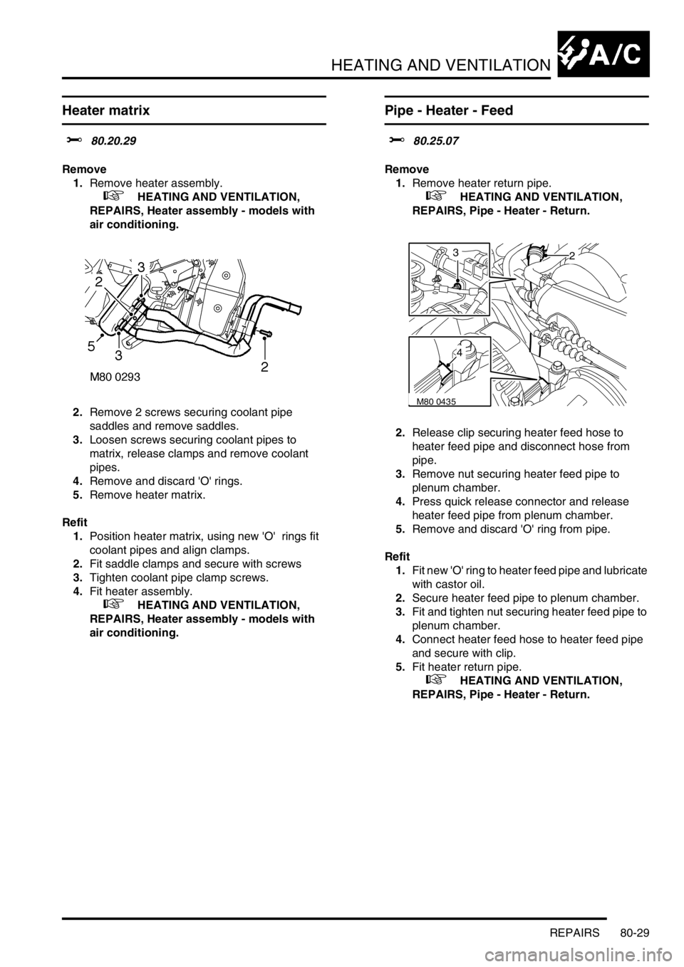
2.Remove 2 screws securing coolant pipe
saddles and remove saddles.
3.Loosen screws securing coolant pipes to
matrix, release clamps and remove coolant
pipes.
4.Remove and discard 'O' rings.
5.Remove heater matrix.
Refit
1.Position heater matrix, using new 'O' rings fit
coolant pipes and align clamps.
2.Fit saddle clamps and secure with screws
3.Tighten coolant pipe clamp screws.
4.Fit heater assembly.
+ HEATING AND VENTILATION,
REPAIRS, Heater assembly - models with
air conditioning.
Pipe - Heater - Feed
$% 80.25.07
Remove
1.Remove heater return pipe.
+ HEATING AND VENTILATION,
REPAIRS, Pipe - Heater - Return.
2.Release clip securing heater feed hose to
heater feed pipe and disconnect hose from
pipe.
3.Remove nut securing heater feed pipe to
plenum chamber.
4.Press quick release connector and release
heater feed pipe from plenum chamber.
5.Remove and discard 'O' ring from pipe.
Refit
1.Fit new 'O' ring to heater feed pipe and lubricate
with castor oil.
2.Secure heater feed pipe to plenum chamber.
3.Fit and tighten nut securing heater feed pipe to
plenum chamber.
4.Connect heater feed hose to heater feed pipe
and secure with clip.
5.Fit heater return pipe.
+ HEATING AND VENTILATION,
REPAIRS, Pipe - Heater - Return.
M80 0435
23
4
Page 1190 of 1529
AIR CONDITIONING
DESCRIPTION AND OPERATION 82-1
AIR CONDITIONING DESCRIPTION AND OPERAT ION
A/C refrigerant system component
layout
Diesel installation shown, V8 similar
1Evaporator and thermostatic expansion valve
2High pressure servicing connection
3To rear A/C system (where fitted)
4Low pressure servicing connection5Refrigerant lines
6Receiver drier
7Condenser
8Compressor