1999 LAND ROVER DISCOVERY air condition
[x] Cancel search: air conditionPage 929 of 1529

RESTRAINT SYSTEMS
75-26 REPAIRS
Air bag - fascia - passenger - deployment
- in vehicle
$% 76.74.17
These guidelines are written to aid authorised
personnel to carry out the safe disposal of air bag
modules when removed from the vehicle.
Deploy
It is imperative that before any work is
undertaken on the SRS system, the
appropriate information is read thoroughly.
1.Make the SRS system safe.
+ GENERAL INFORMATION,
Supplementary Restraint System
Precautions.
2.Release both guides supporting glove box to
fascia.
3.Lower glove box to gain access to air bag
module multiplug.4.Disconnect multiplug from air bag module.
5.Check condition of deployment tool LRT-86-
003 and associated fly leads.
Page 930 of 1529

RESTRAINT SYSTEMS
REPAIRS 75-27
6.Connect deployment tool fly lead LRT-86-003/
04 to air bag.
7.Connect deployment tool LRT-86-003 to
deployment tool fly lead LRT-86-003/04.
8.Connect deployment tool LRT-86-003 to
battery.
WARNING: Ensure all personnel are at least
15 metres (50 feet) away from the air bag
module.
9.Press deployment tool operating button to
deploy air bag module.
10.Disconnect deployment tool from battery.
WARNING: During deployment parts of the
air bag module become hot enough to burn
you. Wait 30 minutes after deployment
before touching the air bag module.
11.Disconnect deployment tool fly lead from air
bag.
12. Do not re-use or salvage any parts of the
SRS system.
NOTE: Do not transport deployed SRS
components in the vehicle passenger
compartment.
Air bag - fascia - passenger - deployment
- off vehicle
$% 76.74.18
These guidelines are written to aid authorised
personnel to carry out the safe disposal of air bag
modules when removed from the vehicle.
Deploy
It is imperative that before any work is
undertaken on the SRS system, the
appropriate information is read thoroughly.
1.Check condition of deployment tool LRT-86-
003 and associated fly leads.
2.Position LRT-86-007/03 in vice, ensuring that
vice jaws grip tool above the bottom flange to
prevent possibility of tool being forced upwards
during detonation. Tighten vice.
3.Fit and secure 2 off LRT-86-007/04 to LRT-86-
007/03.
Page 1005 of 1529
SEATS
76-5-8 DESCRIPTION AND OPERATION
Operation - electric seats
Seat power relay enable line
The BCU provides the seat power relays with an earth supply to the relay coil that enables the relay operation. When
this seat power relay enable line is active, the seat power relay energises allowing seat operation.
In order for the seat power relay to be active the BCU must detect either of the following condition options:
lIgnition switch in position II.
lIgnition switch in position II or driver's door within 45 seconds of opening.
Seat fore/ aft movement
When the cushion switch is operated and the seat power relay enable line is operating, power and earth are supplied
to the motor in the seat, allowing the seat to move forward or backward depending on switch position. The motor
drives a gear wheel along a gear rack connected to the seat base. Sliding the cushion switch forward causes the motor
to drive the seat forward. Sliding the cushion switch rearward reverses polarity of the voltage at the seat motor, driving
the seat rearward.
Seat cushion front up/ down movement
When the cushion switch is operated and the seat power relay enable line is operating, power and earth are supplied
to the motor in the seat, allowing the front of the seat cushion to move upward or downward depending on switch
position. The motor drives a gear wheel along a gear rack connected to the seat base. Sliding the front of the cushion
switch upward causes the motor to drive the seat upward. Sliding the front of the cushion switch downward reverses
polarity of the voltage at the seat motor driving the seat downward.
Seat cushion rear up/ down movement
When the cushion switch is operated and the seat power relay enable line is operating, power and earth are supplied
to the motor in the seat, allowing the seat to move upwards or downwards depending on switch position. The motor
drives a gear wheel along a gear rack connected to the seat base. Sliding the rear of the cushion switch upward
causes the motor to drive the seat upward. Sliding the rear of the cushion switch downward reverses polarity of the
voltage at the seat motor driving the seat downward.
Squab fore/ aft movement
When the squab switch is operated and the seat power relay enable line is operating, power and earth is supplied to
the motor in the squab, allowing the squab to move forward or backward depending on switch position. The motor
drives a gear wheel along a rotary gear rack connected to the squab. Sliding the squab switch forward causes the
motor to drive the squab forward. Sliding the squab switch rearward reverses polarity of the voltage at the seat motor
driving the squab rearward.
Lumbar inflate/ deflate
Sliding the squab switch upwards when the seat power relay enable line is operating applies voltage to the lumbar
pump. The lumbar pump inflates the lumbar bladder, increasing lumbar support. The lumbar pump and the normally
closed lumbar deflate solenoid hold the air in the bladder. Sliding the squab switch downwards applies voltage to the
deflate solenoid, venting the air in the lumbar bladder to atmosphere, decreasing lumbar support.
Diagnostics
TestBook can only verify that the seat power relay line is enabled. It cannot determine the status of the system or any
of the components.
Page 1081 of 1529
PANEL REPAIRS
77-2-14 PROCEDURES
Electronic control units
The electronic control units (ECU) fitted to vehicles make it advisable to follow suitable precautions prior to carrying
out welding repair operations. Harsh conditions of heat and vibration may be generated during these operations which
could cause damage to the units.
In particular, it is essential to follow the appropriate precautions when disconnecting or removing the airbag DCU.
Supplementary Restraint System Precautions
Any work undertaken which involves the removal or replacement of any item of the Supplementary Restraint System
(SRS), requires extreme caution and the appropriate precautions must be followed.
+ GENERAL INFORMATION, Supplementary Restraint System Precautions.
Equipment
Prior to commencing any test procedure on the vehicle, ensure that the relevant test equipment is working correctly
and any harness or connectors are in good condition. This particularly applies to electronic control units.
Page 1088 of 1529
PANEL REPAIRS
REPAIRS 77-2-21
REPAIRS
Front bulkhead assembly
Remove
1.Disconnect both battery leads, negative lead
first.
2.Disconnect leads/multiplug from alternator.
3.Remove front wing.
+ EXTERIOR FITTINGS, REPAIRS,
Wing - front - up to 03MY.
4.Remove washer reservoir.
+ WIPERS AND WASHERS, REPAIRS,
Reservoir - washer - up to 03MY.
5. Models with A/C: Remove condensor.
+ AIR CONDITIONING, REPAIRS,
Condenser.
6. Diesel models: Remove gearbox fluid cooler.
7.Remove RH and LH headlamps.
+ LIGHTING, REPAIRS, Headlamp - up
to 03MY.
8.Release headlamp levelling motors and
position aside.
9.Release headlamp wiring and position aside.
10.Remove battery.
+ CHARGING AND STARTING,
REPAIRS, Battery.
11.Remove battery tray.
12.Remove air filter assembly.
+ ENGINE MANAGEMENT SYSTEM -
Td5, REPAIRS, Air filter assembly.
+ ENGINE MANAGEMENT SYSTEM -
V8, REPAIRS, Air cleaner assembly.
13.Remove 2 earth leads from LH of front
bulkhead.
14.Remove RH horn.
+ ALARM SYSTEM AND HORN,
REPAIR, Vehicle horn.
15. Models with A/C: Release and remove A/C
pipes.
16.Remove RH and LH crush cans.
17.Remove bonnet release cable.
18.Support bonnet in open position
19.Remove bonnet locking mechanism.
20.Remove VIN plate.
21.Remove 2 bolts securing front bulkhead
assembly to chassis.
22.Remove centre braces.Repair
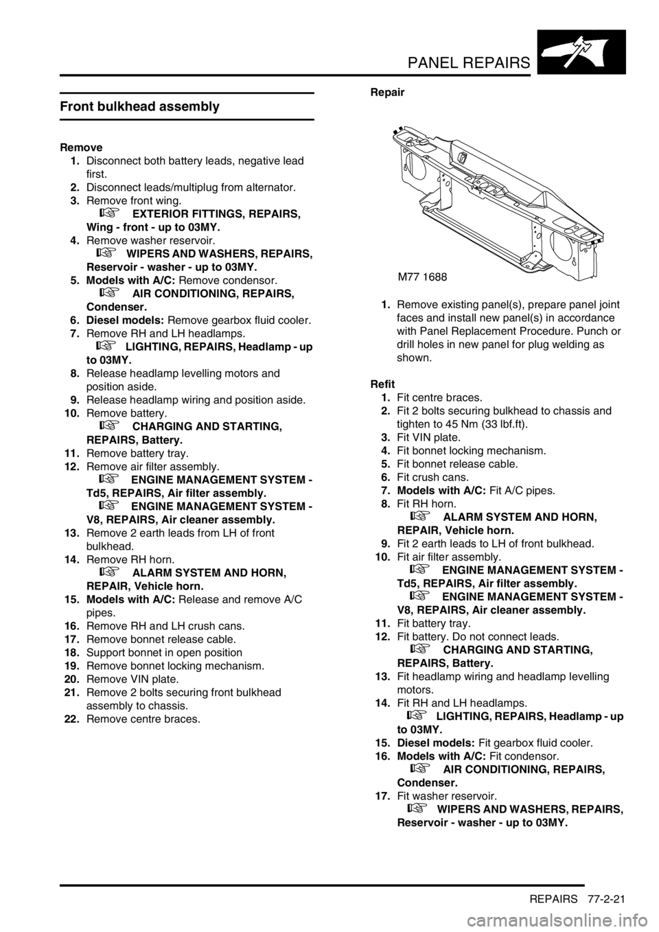
1.Remove existing panel(s), prepare panel joint
faces and install new panel(s) in accordance
with Panel Replacement Procedure. Punch or
drill holes in new panel for plug welding as
shown.
Refit
1.Fit centre braces.
2.Fit 2 bolts securing bulkhead to chassis and
tighten to 45 Nm (33 lbf.ft).
3.Fit VIN plate.
4.Fit bonnet locking mechanism.
5.Fit bonnet release cable.
6.Fit crush cans.
7. Models with A/C: Fit A/C pipes.
8.Fit RH horn.
+ ALARM SYSTEM AND HORN,
REPAIR, Vehicle horn.
9.Fit 2 earth leads to LH of front bulkhead.
10.Fit air filter assembly.
+ ENGINE MANAGEMENT SYSTEM -
Td5, REPAIRS, Air filter assembly.
+ ENGINE MANAGEMENT SYSTEM -
V8, REPAIRS, Air cleaner assembly.
11.Fit battery tray.
12.Fit battery. Do not connect leads.
+ CHARGING AND STARTING,
REPAIRS, Battery.
13.Fit headlamp wiring and headlamp levelling
motors.
14.Fit RH and LH headlamps.
+ LIGHTING, REPAIRS, Headlamp - up
to 03MY.
15. Diesel models: Fit gearbox fluid cooler.
16. Models with A/C: Fit condensor.
+ AIR CONDITIONING, REPAIRS,
Condenser.
17.Fit washer reservoir.
+ WIPERS AND WASHERS, REPAIRS,
Reservoir - washer - up to 03MY.
Page 1090 of 1529
PANEL REPAIRS
REPAIRS 77-2-23
Bonnet locking platform
Remove
1.Disconnect both battery leads, negative lead
first.
2.Disconnect leads/multiplug from alternator.
3.Remove front bumper assembly.
+ EXTERIOR FITTINGS, REPAIRS,
Bumper assembly - front.
4. Models with A/C: Remove condensor.
+ AIR CONDITIONING, REPAIRS,
Condenser.
5. Diesel models: Remove gearbox fluid cooler.
6.Remove RH and LH headlamps.
+ LIGHTING, REPAIRS, Headlamp - up
to 03MY.
7.Remove RH and LH repeater lamps.
+ LIGHTING, REPAIRS, Lamp - front
repeater - up to 03MY.
8.Release headlamp wiring and position aside.
9.Remove battery.
+ CHARGING AND STARTING,
REPAIRS, Battery.
10.Remove battery tray.
11.Remove air filter assembly.
+ ENGINE MANAGEMENT SYSTEM -
Td5, REPAIRS, Air filter assembly.
+ ENGINE MANAGEMENT SYSTEM -
V8, REPAIRS, Air cleaner assembly.
12.Remove RH horn.
+ ALARM SYSTEM AND HORN,
REPAIR, Vehicle horn.
13.Remove bonnet release cable.
14.Support bonnet in open position
15.Remove bonnet locking mechanism.
16.Remove VIN plate.
17.Remove centre braces.Repair
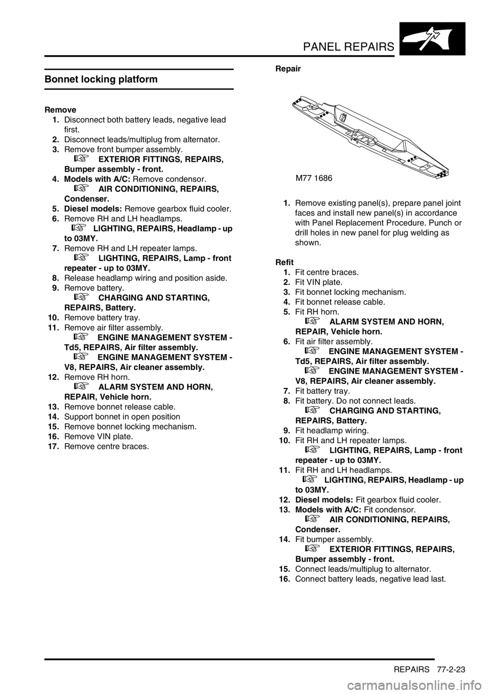
1.Remove existing panel(s), prepare panel joint
faces and install new panel(s) in accordance
with Panel Replacement Procedure. Punch or
drill holes in new panel for plug welding as
shown.
Refit
1.Fit centre braces.
2.Fit VIN plate.
3.Fit bonnet locking mechanism.
4.Fit bonnet release cable.
5.Fit RH horn.
+ ALARM SYSTEM AND HORN,
REPAIR, Vehicle horn.
6.Fit air filter assembly.
+ ENGINE MANAGEMENT SYSTEM -
Td5, REPAIRS, Air filter assembly.
+ ENGINE MANAGEMENT SYSTEM -
V8, REPAIRS, Air cleaner assembly.
7.Fit battery tray.
8.Fit battery. Do not connect leads.
+ CHARGING AND STARTING,
REPAIRS, Battery.
9.Fit headlamp wiring.
10.Fit RH and LH repeater lamps.
+ LIGHTING, REPAIRS, Lamp - front
repeater - up to 03MY.
11.Fit RH and LH headlamps.
+ LIGHTING, REPAIRS, Headlamp - up
to 03MY.
12. Diesel models: Fit gearbox fluid cooler.
13. Models with A/C: Fit condensor.
+ AIR CONDITIONING, REPAIRS,
Condenser.
14.Fit bumper assembly.
+ EXTERIOR FITTINGS, REPAIRS,
Bumper assembly - front.
15.Connect leads/multiplug to alternator.
16.Connect battery leads, negative lead last.
Page 1091 of 1529
PANEL REPAIRS
77-2-24 REPAIRS
Front cross member
Remove
1.Disconnect both battery leads, negative lead
first.
2.Disconnect leads/multiplug from alternator.
3.Remove washer reservoir.
+ WIPERS AND WASHERS, REPAIRS,
Reservoir - washer - up to 03MY.
4. Models with A/C: Remove condensor.
+ AIR CONDITIONING, REPAIRS,
Condenser.
5. Diesel models: Remove gearbox fluid cooler.
6.Remove RH and LH headlamps.
+ LIGHTING, REPAIRS, Headlamp - up
to 03MY.
7.Release headlamp levelling motors and
position aside.
8.Release headlamp wiring and position aside.
9.Remove RH horn.
+ ALARM SYSTEM AND HORN,
REPAIR, Vehicle horn.
10. Models with A/C: Release and remove A/C
pipes.
11.Remove RH and LH crush cans.
12.Remove 2 bolts securing front bulkhead
assembly to chassis.
13.Remove centre braces.
Repair
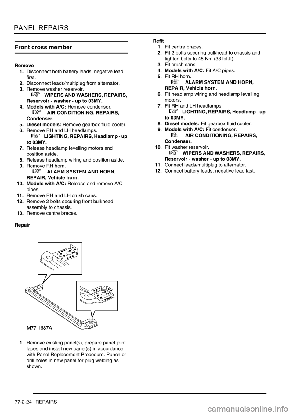
1.Remove existing panel(s), prepare panel joint
faces and install new panel(s) in accordance
with Panel Replacement Procedure. Punch or
drill holes in new panel for plug welding as
shown.Refit
1.Fit centre braces.
2.Fit 2 bolts securing bulkhead to chassis and
tighten bolts to 45 Nm (33 lbf.ft).
3.Fit crush cans.
4. Models with A/C: Fit A/C pipes.
5.Fit RH horn.
+ ALARM SYSTEM AND HORN,
REPAIR, Vehicle horn.
6.Fit headlamp wiring and headlamp levelling
motors.
7.Fit RH and LH headlamps.
+ LIGHTING, REPAIRS, Headlamp - up
to 03MY.
8. Diesel models: Fit gearbox fluid cooler.
9. Models with A/C: Fit condensor.
+ AIR CONDITIONING, REPAIRS,
Condenser.
10.Fit washer reservoir.
+ WIPERS AND WASHERS, REPAIRS,
Reservoir - washer - up to 03MY.
11.Connect leads/multiplug to alternator.
12.Connect battery leads, negative lead last.
Page 1092 of 1529
PANEL REPAIRS
REPAIRS 77-2-25
Headlamp mounting panel - RH
Remove
1.Disconnect both battery leads, negative lead
first.
2.Disconnect leads/multiplug from alternator.
3.Remove front bumper assembly.
+ EXTERIOR FITTINGS, REPAIRS,
Bumper assembly - front.
4. Models with A/C: Remove condensor.
+ AIR CONDITIONING, REPAIRS,
Condenser.
5. Diesel models: Remove gearbox fluid cooler.
6.Remove RH headlamp.
+ LIGHTING, REPAIRS, Headlamp - up
to 03MY.
7.Remove RH repeater lamp.
+ LIGHTING, REPAIRS, Lamp - front
repeater - up to 03MY.
8.Release headlamp levelling motor and position
aside.
9.Release headlamp wiring and position aside.
10.Remove battery and battery tray.
+ CHARGING AND STARTING,
REPAIRS, Battery.
11.Remove horn.
+ ALARM SYSTEM AND HORN,
REPAIR, Vehicle horn.
12.Remove RH crush can.
13.Remove 2 bolts securing front bulkhead
assembly to chassis.
14.Remove RH centre brace.Repair
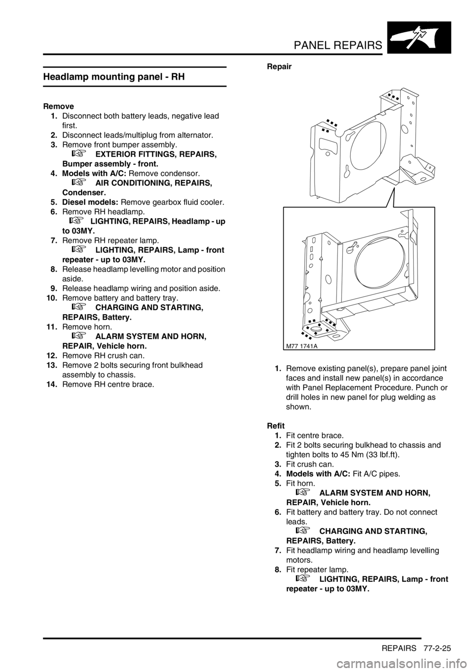
1.Remove existing panel(s), prepare panel joint
faces and install new panel(s) in accordance
with Panel Replacement Procedure. Punch or
drill holes in new panel for plug welding as
shown.
Refit
1.Fit centre brace.
2.Fit 2 bolts securing bulkhead to chassis and
tighten bolts to 45 Nm (33 lbf.ft).
3.Fit crush can.
4. Models with A/C: Fit A/C pipes.
5.Fit horn.
+ ALARM SYSTEM AND HORN,
REPAIR, Vehicle horn.
6.Fit battery and battery tray. Do not connect
leads.
+ CHARGING AND STARTING,
REPAIRS, Battery.
7.Fit headlamp wiring and headlamp levelling
motors.
8.Fit repeater lamp.
+ LIGHTING, REPAIRS, Lamp - front
repeater - up to 03MY.
M77 1741A