1999 LAND ROVER DISCOVERY air condition
[x] Cancel search: air conditionPage 1207 of 1529

AIR CONDITIONING
82-18DESCRIPTION AND OPERATION
Air distribution control
To control the air distribution within the cabin the ATC ECU signals the servo motor controlling the distribution flaps
in the heater assembly to move to the flaps to the appropriate position.
In the automatic and economy modes, if the LH or RH temperature selections are set to LO or HI, air distribution is
fixed as follows:
lIf one is set to LO and one is set to a specific temperature, to face level only.
lIf one is set to HI and one is set to a specific temperature, to footwells only.
lIf one is set to LO and one is set to HI, to face level and footwells.
When specific LH and RH temperature selections are set, air distribution is determined from the target air outlet
temperatures. For higher target air outlet temperatures, air distribution is set to footwells only. For lower target air
outlet temperatures, air distribution is set to face level only. For intermediate target air outlet temperatures, air
distribution is set to face level and footwells. When the air distribution is set to face level and footwells, the ATC ECU
varies the bias between the footwells and the face level outlets, in three stages, to provide a gradual transition of air
distribution from footwells only to face level only. The three stages of bias are also employed when the air distribution
is manually selected to face level and footwells.
During warm-up, the air distribution changes to face level and footwells for a period, then reverts to footwells only.
The period of air distribution at face level and footwells can be cancelled by pressing and holding the on/off and defrost
mode switches, then turning the ignition switch from off to on. Pressing and holding the AUTO and defrost switches,
then turning the ignition switch from off to on, restores the period of air distribution at face level and footwells.
Compressor control
To engage the compressor clutch, the ATC ECU outputs a compressor clutch request to the ECM, which then
energises the A/C compressor clutch relay. Compressor operation is governed by the evaporator outlet air
temperature, at one of two settings, dependent on the amount of cooling required. When more cooling is required, the
compressor clutch request is output if evaporator outlet air temperature increases to 4 °C (39 °F) and cancelled when
it decreases to 3 °C (37 °F). When less cooling is required, the compressor clutch request is output if evaporator outlet
air temperature increases to 11 °C (52 °F) and cancelled when it decreases to 10 °C (50 °F).
Engine cooling fan control
While the A/C system is on, operation of the electric engine cooling fan, to assist refrigerant condenser operation, is
determined by a combination of vehicle speed and external air temperature. When cooling fan operation is required,
the ATC ECU outputs a cooling fan request to the ECM, which then energises the cooling fan relay. The cooling fan
request is output if vehicle speed is 80 km/h or less while the external air temperature is 28 °C (82 °F) or more. The
request is cancelled, and the cooling fan switched off, if either the vehicle speed increases to 100 km/h, or the external
air temperature decreases to 25 °C (77 °F).
Default settings
If the battery power supply to the ATC ECU is disrupted for any reason, e.g. battery disconnected, the system reverts
to default settings when the battery power supply is restored. Default settings are:
lTemperature indications in °C (in some markets a conversion connector is fitted to the ATC ECU to change the
default temperature scale to °F).
lLH and RH outlet temperatures of 22 °C (72 °F).
laudible warning switched on.
lWarm-up air distribution (to face level and footwells) function switched on.
lIf the system is first switched on using the A/C on/off switch, the automatic mode is engaged, regardless of the
settings in use when the battery was disconnected.
Page 1208 of 1529

AIR CONDITIONING
DESCRIPTION AND OPERATION 82-19
Diagnostics
The ATC ECU performs a diagnostic check each time the ignition is switched on. To avoid nuisance fault indications
at low light levels, the sunlight sensor is omitted from the diagnostic check. If a fault is detected, the audible warning
sounds three times and the AUTO window on the control panel display flashes for 20 seconds. The ATC ECU then
reverts to normal control but uses a default value or strategy for the detected fault. Faults are identified by performing
a manual diagnostic check of the system.
A manual diagnostic check includes a check of the sunlight sensor, and is initiated by pressing and holding the AUTO
switch and the air distribution switch, then turning the ignition switch from off to on. The audible warning sounds once
and the indications on the control panel display illuminate. FC is shown in the LH temperature window and the results
of the check are shown as a two digit fault code in the RH temperature window. If a fault is detected, the audible
warning sounds three times and the AUTO window on the display flashes on and off for 20 seconds. If more than one
fault is detected, the fault codes cycle in numerical order, at 1 Hz. The audible warning sounds as each fault code is
shown. In low light conditions, to avoid false sunlight sensor fault indications, the sunlight sensor should be illuminated
with a strong light source.
Diagnostic fault codes and fault descriptions
Code Component Fault Default value/strategy
00 - No fault found -
11 In-car temperature sensor Open or short circuit 25°C (77°F)
12 Ambient temperature sensor Open or short circuit 10°C (50°F)
Cooling fan permanently on
Display shows "- -" if external air
temperature selected
13 Thermistor Open or short circuit 0°C (32°F)
14 Heater coolant temperature sensor Open or short circuit 70°C (158°F)
21 Sunlight sensor, left output Open or short circuit No solar heating correction
22 Sunlight sensor, right output Open or short circuit No solar heating correction
31 LH temperature servo motor Open or short circuit
Motor or flap mechanism seizedServo motor locked in position
32 RH temperature servo motor Open or short circuit
Motor or flap mechanism seizedServo motor locked in position
33 Distribution servo motor Open or short circuit
Motor or flap mechanism seizedServo motor locked in position
Page 1210 of 1529

AIR CONDITIONING
DESCRIPTION AND OPERATION 82-21
DESCRIPTION AND OPERAT ION
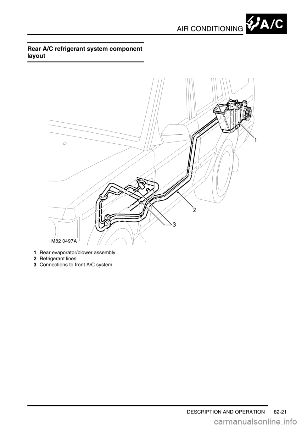
Rear A/C refrigerant system component
layout
1Rear evaporator/blower assembly
2Refrigerant lines
3Connections to front A/C system
Page 1211 of 1529

AIR CONDITIONING
82-22DESCRIPTION AND OPERATION
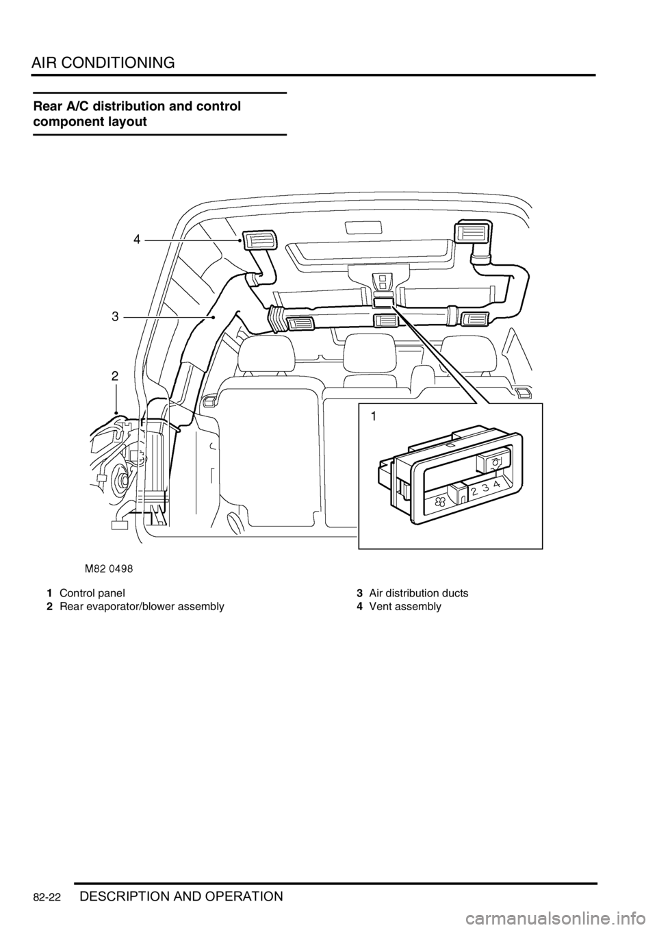
Rear A/C distribution and control
component layout
1Control panel
2Rear evaporator/blower assembly3Air distribution ducts
4Vent assembly
Page 1212 of 1529

AIR CONDITIONING
DESCRIPTION AND OPERATION 82-23
Description
The rear air conditioning system cools and recirculates air at the rear of the cabin. The system consists of refrigerant
lines, a rear evaporator/blower assembly, a distribution system and a control panel.
Cooled air from the rear evaporator/blower assembly is supplied by the distribution system to vent outlets above each
second and third row seat. The system is controlled by two switches on the control panel.
Refrigerant lines
Two refrigerant lines connect the rear evaporator/blower assembly to the front A/C refrigerant system. The lines are
routed along the LH underside of the vehicle and secured to a connector block in the floor. A heat shield protects the
lines where they pass above the rear silencer.
Page 1213 of 1529

AIR CONDITIONING
82-24DESCRIPTION AND OPERATION
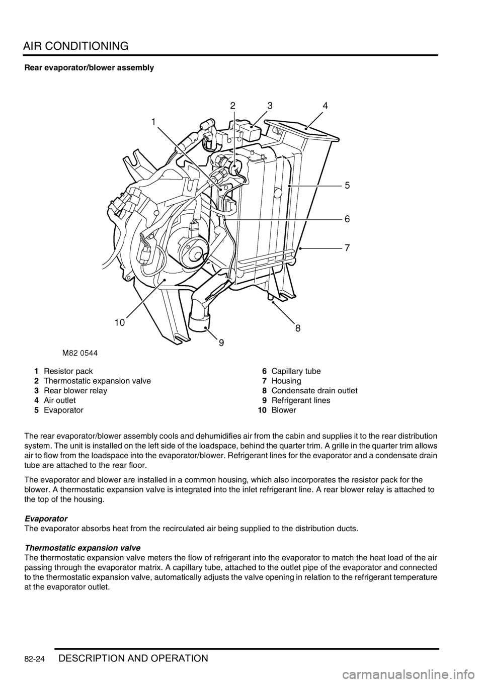
Rear evaporator/blower assembly
1Resistor pack
2Thermostatic expansion valve
3Rear blower relay
4Air outlet
5Evaporator6Capillary tube
7Housing
8Condensate drain outlet
9Refrigerant lines
10Blower
The rear evaporator/blower assembly cools and dehumidifies air from the cabin and supplies it to the rear distribution
system. The unit is installed on the left side of the loadspace, behind the quarter trim. A grille in the quarter trim allows
air to flow from the loadspace into the evaporator/blower. Refrigerant lines for the evaporator and a condensate drain
tube are attached to the rear floor.
The evaporator and blower are installed in a common housing, which also incorporates the resistor pack for the
blower. A thermostatic expansion valve is integrated into the inlet refrigerant line. A rear blower relay is attached to
the top of the housing.
Evaporator
The evaporator absorbs heat from the recirculated air being supplied to the distribution ducts.
Thermostatic expansion valve
The thermostatic expansion valve meters the flow of refrigerant into the evaporator to match the heat load of the air
passing through the evaporator matrix. A capillary tube, attached to the outlet pipe of the evaporator and connected
to the thermostatic expansion valve, automatically adjusts the valve opening in relation to the refrigerant temperature
at the evaporator outlet.
Page 1214 of 1529

AIR CONDITIONING
DESCRIPTION AND OPERATION 82-25
Blower
The blower controls the volume of air being supplied to the distribution outlets. The blower is an open hub, centrifugal
fan powered by an electric motor. A dust filter is installed over the fan inlet. The blower switch on the control panel
and the resistor pack control the operation of the blower, which can be selected to run at one of four speeds.
Resistor pack
The resistor pack supplies reduced voltages to the blower motor for blower speeds 1, 2 and 3. For blower speed 4,
the resistor pack is bypassed and battery voltage drives the motor at full speed. The pack is installed in the air outlet
from the blower fan, so that any heat generated is dissipated by the air flow.
Distribution system
Air ducts
Ducts connected to the rear evaporator/blower motor assembly distribute air to five vent assemblies in the roof.
Vent assemblies
The vent assemblies allow occupants to control the flow and direction of air. Each vent assembly incorporates a
thumbwheel to regulate flow and moveable vanes to control direction.
Rear control system
The control system operates the blower to control the operation of the rear A/C. The control system consists of two
control switches and a rear blower relay.
Control switches
A rear A/C switch and a blower speed switch are installed on a control panel in the roof lining. The A/C switch is a
latching pushswitch with an amber indicator lamp which illuminates when rear A/C is selected on. The blower speed
switch is a slide switch with a positive detent at each of four speed positions (there is no off position).
Rear blower relay
The rear blower relay controls the electrical supply to the blower.
Page 1215 of 1529

AIR CONDITIONING
82-26DESCRIPTION AND OPERATION
Operation
The rear A/C only operates if the front A/C is on to pump refrigerant through the rear evaporator/blower assembly.
When the rear A/C switch is selected on, the indicator lamp in the switch illuminates and the rear blower relay is
energised. The rear blower relay switches battery power to the blower motor, which runs at the speed selected on the
blower speed switch.
The air from the blower passes through the evaporator matrix, which absorbs heat from the air. The cooled air is then
supplied to the roof vents through the distribution ducts. The heat absorbed by the refrigerant in the evaporator is
sensed by the thermostatic expansion valve. The thermostatic expansion valve then opens and regulates the flow of
refrigerant through the evaporator in proportion to the amount of heat being absorbed from the air.
When the rear A/C switch is selected off, the blower stops. The thermostatic expansion valve senses the subsequent
decrease in temperature of the refrigerant in the evaporator. The thermostatic expansion valve then closes and stops
the flow of refrigerant, except for a minimal bleed flow.