1999 LAND ROVER DISCOVERY ECO mode
[x] Cancel search: ECO modePage 1394 of 1529
IN CAR ENTERTAINMENT
DESCRIPTION AND OPERATION 86-6-27
Operation
DVD Player Functionality
The following defines the functionality of the unit. Further details of system operation can found in the DVD System
Owner's Manual, Publication Part No. LRL0482, supplied with the system.
DVD Region Selection
The DVD player is capable of playing discs from any region. The DVD can only be set to play discs of one region at
a time. A code is entered using the remote control handset to set the unit to the required region. The unit is set to the
correct region on production and therefore this will not be required by either the dealer or the customer.
If the unit region is required to be changed for any reason, Land Rover Special Vehicles must be contacted for the
required code and procedure.
NOTE: The unit can be re-configured for region up to five times. After the fifth attempt to re-configure the region, the
unit will be locked in the fifth region that was programmed. This will require the unit to be returned to the manufacturer
to be reset. The manufacturer will charge a fee for this service.
DVD Player CD Audio Function
The DVD player can play audio CD's through the vehicle audio system. This allows the user to play additional CD's
without having to remove the CD autochanger cartridge.
The overhead console LCD monitor must be open to play audio CD's.. Normal audio CD functionality such as repeat,
random and track select etc. can be accessed using the remote control handset.
The DVD player in the overhead console will also function independently of the vehicle audio system, and operate as
an additional CD player. The rear seat passengers can listen to audio CD's via the three headphone sockets on the
overhead console and via the two radio/headphone amplifier units (if fitted), while the front seat passengers
simultaneously listen to CD's played on the vehicle audio system and CD autochanger.
DVD/CD Output using the Vehicle Audio System
To play the DVD/CD audio output from the overhead console through the vehicle audio speakers, the speaker button
on the overhead console or remote control handset must be pressed. 'Speaker On' appears on the LCD monitor and
the head unit CD functionality is suspended. The audio output from the overhead console will now be played from the
vehicle speaker system. The head unit volume control, tone control, Navigation announcements and mobile phone (if
fitted) will function as normal and override the DVD output. A second press of the speaker button will switch the audio
output back to the head unit. 'Speaker Off' will be displayed on the LCD monitor.
The overhead console will remember the selected speaker condition if the overhead console is switched off by closing
the monitor, the console switched off using the handset or accessory power removed from the overhead console.
Power Up Conditions
On application of accessory power, the overhead console will perform the following:
lIf no disc is in the DVD player, the LCD monitor will display a blue screen and enter 'AUX' input mode.
When a DVD or CD is inserted in the DVD player, the system will change to DVD input mode. The disc will
attempt to play but may be limited by the disc media. Some discs will play automatically, some will display a menu
and others require the user to start playback.
lIf a disc was in the DVD player and the system was in 'Play', 'Pause', 'FF' or 'Rew' when powered down, playback
will start when power is re-applied.
lIf a disc was in the DVD player and the system was in 'Stop' when powered down, the system will enter DVD
mode and a blue screen will be displayed on the LCD monitor.
lSpeaker selection will remain in the same state as when the accessory power was removed.
Engine Cranking
If the unit is playing a DVD or CD when the ignition switch is moved to position III (engine crank), the system will stop
playing while the engine is cranking. Playback will resume at the point the playback was stopped when the ignition
switch is returned to position I or II.
Page 1449 of 1529
DRIVING AIDS
86-8-12 DESCRIPTION AND OPERATION
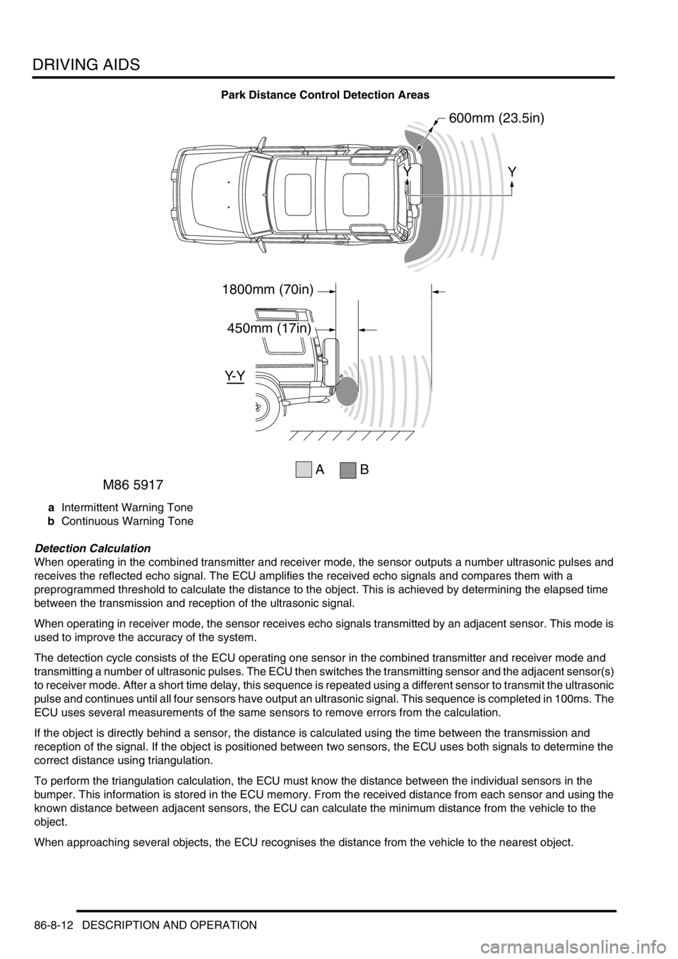
Park Distance Control Detection Areas
aIntermittent Warning Tone
bContinuous Warning Tone
Detection Calculation
When operating in the combined transmitter and receiver mode, the sensor outputs a number ultrasonic pulses and
receives the reflected echo signal. The ECU amplifies the received echo signals and compares them with a
preprogrammed threshold to calculate the distance to the object. This is achieved by determining the elapsed time
between the transmission and reception of the ultrasonic signal.
When operating in receiver mode, the sensor receives echo signals transmitted by an adjacent sensor. This mode is
used to improve the accuracy of the system.
The detection cycle consists of the ECU operating one sensor in the combined transmitter and receiver mode and
transmitting a number of ultrasonic pulses. The ECU then switches the transmitting sensor and the adjacent sensor(s)
to receiver mode. After a short time delay, this sequence is repeated using a different sensor to transmit the ultrasonic
pulse and continues until all four sensors have output an ultrasonic signal. This sequence is completed in 100ms. The
ECU uses several measurements of the same sensors to remove errors from the calculation.
If the object is directly behind a sensor, the distance is calculated using the time between the transmission and
reception of the signal. If the object is positioned between two sensors, the ECU uses both signals to determine the
correct distance using triangulation.
To perform the triangulation calculation, the ECU must know the distance between the individual sensors in the
bumper. This information is stored in the ECU memory. From the received distance from each sensor and using the
known distance between adjacent sensors, the ECU can calculate the minimum distance from the vehicle to the
object.
When approaching several objects, the ECU recognises the distance from the vehicle to the nearest object.
A
Y- Y
1800mm (70in)
450mm (17in)
600mm (23.5in)
YY
B
M86 5917
Page 1458 of 1529

NAVIGATION SYSTEM
DESCRIPTION AND OPERATION 87-5
System Settings Menu
The system settings menu provides access to features that can be changed to suit market and personal preferences
and to navigation system operating features. On European systems, the system settings menu also includes
computer games and a currency converter. While the navigation computer is in the navigation mode, the system
settings menu can be accessed by pressing the Nav button. Using the RH rotary control, the following features can
be selected and adjusted:
lTIME – Allows the navigation system clock to be set to local time as opposed to the Greenwich Mean Time (GMT)
transmitted from the GPS satellites. The local time setting is necessary for correct navigation on routes with time
restrictions and for Estimated Time of Arrival (ETA) calculations. The time can only be adjusted in 30 minute
steps.
lSAVE POSITION– Allows the current vehicle position to be saved and allocated a name in the navigation
destination memory.
lGAMES – Provides access to a selection of computer games.
lLANGUAGE– Allows the navigation system language and voice (where applicable) to be changed.
lANIMATIONS– Allows the LCD animations to be switched on and off.
lMEASURING UNIT – Allows the route guidance distances displayed on the LCD to be switched between metric
and Imperial units.
lANNOUNCEMENT ETA – Allows the route guidance ETA announcement to be switched on and off.
lCALCULATE EURO – Provides access to a currency converter.
User Menu
The user menu provides access to further features that can be changed to suit personal preferences. While the
navigation computer is in navigation, radio or CD modes, the user menu can be accessed by pressing and holding
the tone button for more than 2 seconds. The user menu is displayed over two screens, which can be toggled between
using the ⇒ multifunction button. Using the appropriate multifunction button or the RH rotary control, the following
settings can be selected and adjusted:
Screen 1
lGal – Automatic volume control setting (see above).
lTel – If a handsfree telephone system is connected to the navigation computer, allows either mute (telephone
mute mode) or audio signal (telephone conversation via the ICE speakers) to be selected.
lLcd – The LCD can be set to appear negative, positiveor automatic. In automatic, the display will be positive or
negative, depending on the setting of the exterior lamps.
lLed – A Light Emitting Diode (LED) in the display can be set to off or blinking. When set to blinking, the LED
flashes when the navigation computer is switched off.
lM/S – Radio reception can be set to Stereo, Mono or Auto, to suppress interference and reflections and so
optimise reception. Stereo is for exceptionally good reception conditions. Mono is for poor reception conditions.
In auto, the normal setting, the navigation computer automatically switches between stereo and mono depending
on reception conditions.
Screen 2
lNav – Sets how audio navigation instructions are delivered. In onl, other audio sources are suppressed and only
the navigation instruction is output to the speakers. In mixed, the volume of any other audio source is reduced
and the volume of the navigation announcement is the same as the original audio source +/– 6 dB (adjustable).
In independ, the audio source and navigation announcement can be set to independent volume levels.
lAux – Used to switch auxiliary CD AF connections between Aux mode on and Aux mode off. If no CD
autochanger is installed, an external cassette or CD player can be connected to the navigation computer and
powered by switching on the auxiliary CD AF connections.
lCmp – Allows a compass to be shown on the LCD when route guidance is not active.
lBeV – Used to adjust the signal tone volume. Signal tones sound to confirm storage confirmation etc. and can
be set between 0 (quiet) and +5 (loud).
Page 1475 of 1529
NAVIGATION SYSTEM
87-22 DESCRIPTION AND OPERATION
On-Board Monitor (Display Unit)
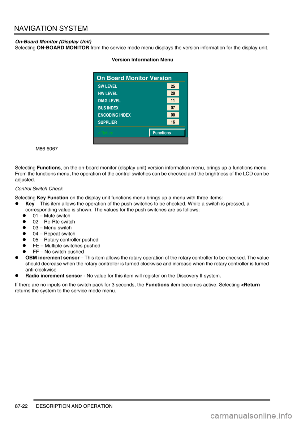
Selecting ON-BOARD MONITOR from the service mode menu displays the version information for the display unit.
Version Information Menu
Selecting Functions, on the on-board monitor (display unit) version information menu, brings up a functions menu.
From the functions menu, the operation of the control switches can be checked and the brightness of the LCD can be
adjusted.
Control Switch Check
Selecting Key Function on the display unit functions menu brings up a menu with three items:
lKey – This item allows the operation of the push switches to be checked. While a switch is pressed, a
corresponding value is shown. The values for the push switches are as follows:
l01 – Mute switch
l02 – Re-Rte switch
l03 – Menu switch
l04 – Repeat switch
l05 – Rotary controller pushed
lFE – Multiple switches pushed
lFF – No switch pushed
lOBM increment sensor – This item allows the rotary operation of the rotary controller to be checked. The value
should decrease when the rotary controller is turned clockwise and increase when the rotary controller is turned
anti-clockwise
lRadio increment sensor - No value for this item will register on the Discovery II system.
If there are no inputs on the switch pack for 3 seconds, the Functions item becomes active. Selecting
M86 6067
On Board Monitor Version
SW LEVEL
HW LEVEL
DIAG LEVEL
BUS INDEX
ENCODING INDEX
SUPPLIER
< Return25
20
11
07
00
16
Functions
Page 1480 of 1529
NAVIGATION SYSTEM
DESCRIPTION AND OPERATION 87-27
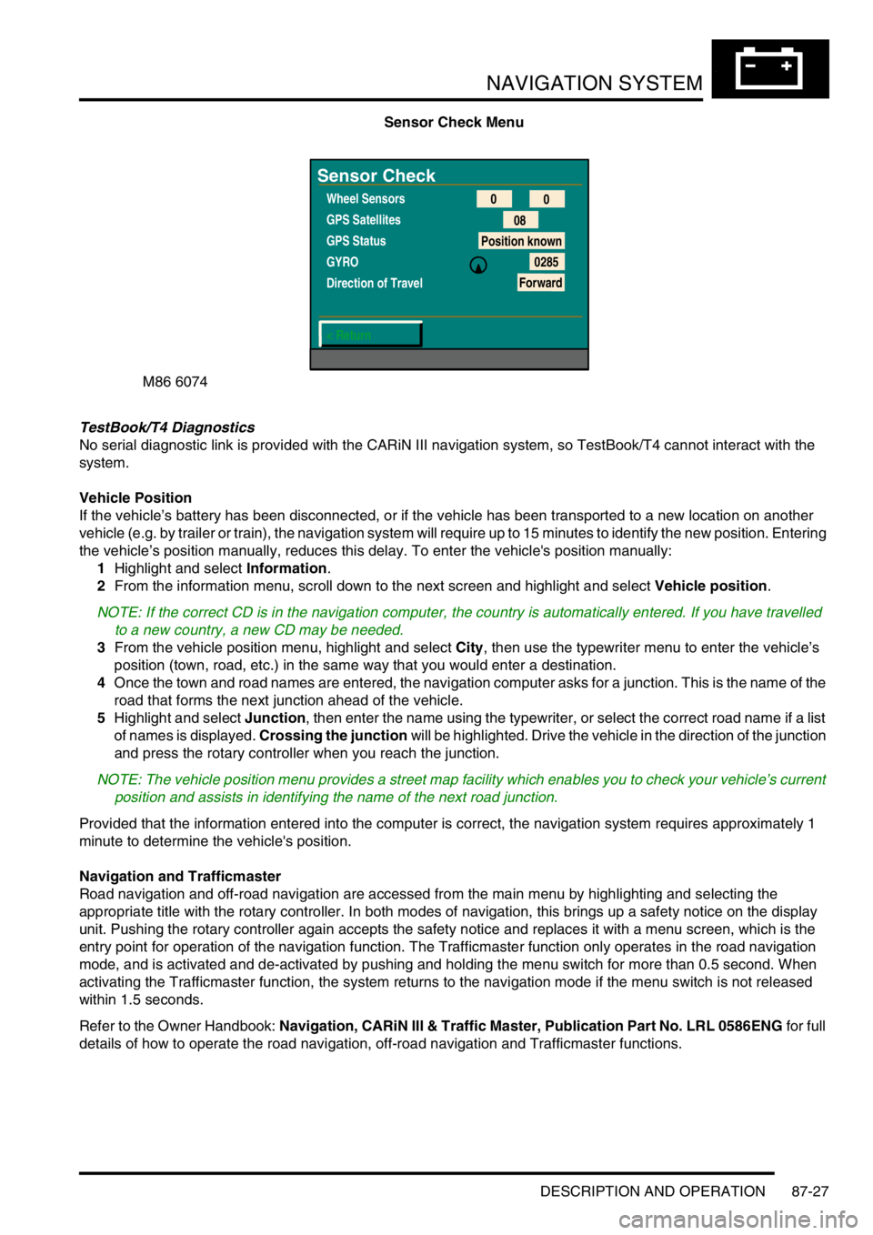
Sensor Check Menu
TestBook/T4 Diagnostics
No serial diagnostic link is provided with the CARiN III navigation system, so TestBook/T4 cannot interact with the
system.
Vehicle Position
If the vehicle’s battery has been disconnected, or if the vehicle has been transported to a new location on another
vehicle (e.g. by trailer or train), the navigation system will require up to 15 minutes to identify the new position. Entering
the vehicle’s position manually, reduces this delay. To enter the vehicle's position manually:
1Highlight and select Information.
2From the information menu, scroll down to the next screen and highlight and select Vehicle position.
NOTE: If the correct CD is in the navigation computer, the country is automatically entered. If you have travelled
to a new country, a new CD may be needed.
3From the vehicle position menu, highlight and select City, then use the typewriter menu to enter the vehicle’s
position (town, road, etc.) in the same way that you would enter a destination.
4Once the town and road names are entered, the navigation computer asks for a junction. This is the name of the
road that forms the next junction ahead of the vehicle.
5Highlight and select Junction, then enter the name using the typewriter, or select the correct road name if a list
of names is displayed. Crossing the junction will be highlighted. Drive the vehicle in the direction of the junction
and press the rotary controller when you reach the junction.
NOTE: The vehicle position menu provides a street map facility which enables you to check your vehicle’s current
position and assists in identifying the name of the next road junction.
Provided that the information entered into the computer is correct, the navigation system requires approximately 1
minute to determine the vehicle's position.
Navigation and Trafficmaster
Road navigation and off-road navigation are accessed from the main menu by highlighting and selecting the
appropriate title with the rotary controller. In both modes of navigation, this brings up a safety notice on the display
unit. Pushing the rotary controller again accepts the safety notice and replaces it with a menu screen, which is the
entry point for operation of the navigation function. The Trafficmaster function only operates in the road navigation
mode, and is activated and de-activated by pushing and holding the menu switch for more than 0.5 second. When
activating the Trafficmaster function, the system returns to the navigation mode if the menu switch is not released
within 1.5 seconds.
Refer to the Owner Handbook: Navigation, CARiN III & Traffic Master, Publication Part No. LRL 0586ENG for full
details of how to operate the road navigation, off-road navigation and Trafficmaster functions.
M86 6074
Sensor Check
Wheel Sensors
GPS Satellites
GPS Status
GYRO
Direction of Travel
< Return0
0
08
Position known
0285
Forward
Page 1495 of 1529
INSTRUMENTS
88-12 DESCRIPTION AND OPERATION
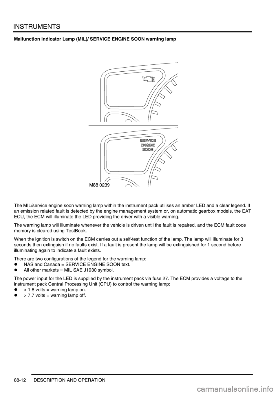
Malfunction Indicator Lamp (MIL)/ SERVICE ENGINE SOON warning lamp
The MIL/service engine soon warning lamp within the instrument pack utilises an amber LED and a clear legend. If
an emission related fault is detected by the engine management system or, on automatic gearbox models, the EAT
ECU, the ECM will illuminate the LED providing the driver with a visible warning.
The warning lamp will illuminate whenever the vehicle is driven until the fault is repaired, and the ECM fault code
memory is cleared using TestBook.
When the ignition is switch on the ECM carries out a self-test function of the lamp. The lamp will illuminate for 3
seconds then extinguish if no faults exist. If a fault is present the lamp will be extinguished for 1 second before
illuminating again to indicate a fault exists.
There are two configurations of the legend for the warning lamp:
lNAS and Canada = SERVICE ENGINE SOON text.
lAll other markets = MIL SAE J1930 symbol.
The power input for the LED is supplied by the instrument pack via fuse 27. The ECM provides a voltage to the
instrument pack Central Processing Unit (CPU) to control the warning lamp:
l< 1.8 volts = warning lamp on.
l> 7.7 volts = warning lamp off.
Page 1509 of 1529
INSTRUMENTS
88-26 DESCRIPTION AND OPERATION
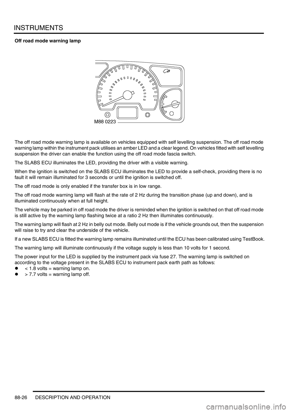
Off road mode warning lamp
The off road mode warning lamp is available on vehicles equipped with self levelling suspension. The off road mode
warning lamp within the instrument pack utilises an amber LED and a clear legend. On vehicles fitted with self levelling
suspension the driver can enable the function using the off road mode fascia switch.
The SLABS ECU illuminates the LED, providing the driver with a visible warning.
When the ignition is switched on the SLABS ECU illuminates the LED to provide a self-check, providing there is no
fault it will remain illuminated for 3 seconds or until the ignition is switched off.
The off road mode is only enabled if the transfer box is in low range.
The off road mode warning lamp will flash at the rate of 2 Hz during the transition phase (up and down), and is
illuminated continuously when at full height.
The vehicle may be parked in off road mode the driver is reminded when the ignition is switched on that off road mode
is still active by the warning lamp flashing twice at a ratio 2 Hz then illuminates continuously.
The warning lamp will flash at 2 Hz in belly out mode. Belly out mode is if the vehicle grounds out, then the suspension
will raise to try and clear the underside of the vehicle.
If a new SLABS ECU is fitted the warning lamp remains illuminated until the ECU has been calibrated using TestBook.
The warning lamp will illuminate continuously if the voltage supply is less than 10 volts for 1 second.
The power input for the LED is supplied by the instrument pack via fuse 27. The warning lamp is switched on
according to the voltage present in the SLABS ECU to instrument pack earth path as follows:
l< 1.8 volts = warning lamp on.
l> 7.7 volts = warning lamp off.
Page 1519 of 1529
INSTRUMENTS
88-36 DESCRIPTION AND OPERATION
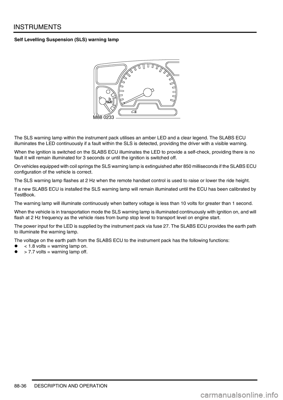
Self Levelling Suspension (SLS) warning lamp
The SLS warning lamp within the instrument pack utilises an amber LED and a clear legend. The SLABS ECU
illuminates the LED continuously if a fault within the SLS is detected, providing the driver with a visible warning.
When the ignition is switched on the SLABS ECU illuminates the LED to provide a self-check, providing there is no
fault it will remain illuminated for 3 seconds or until the ignition is switched off.
On vehicles equipped with coil springs the SLS warning lamp is extinguished after 850 milliseconds if the SLABS ECU
configuration of the vehicle is correct.
The SLS warning lamp flashes at 2 Hz when the remote handset control is used to raise or lower the ride height.
If a new SLABS ECU is installed the SLS warning lamp will remain illuminated until the ECU has been calibrated by
TestBook.
The warning lamp will illuminate continuously when battery voltage is less than 10 volts for greater than 1 second.
When the vehicle is in transportation mode the SLS warning lamp is illuminated continuously with ignition on, and will
flash at 2 Hz frequency as the vehicle rises from bump stop level to transport level on engine start.
The power input for the LED is supplied by the instrument pack via fuse 27. The SLABS ECU provides the earth path
to illuminate the warning lamp.
The voltage on the earth path from the SLABS ECU to the instrument pack has the following functions:
l< 1.8 volts = warning lamp on.
l> 7.7 volts = warning lamp off.