Page 294 of 1529

EMISSION CONTROL - V8
REPAIRS 17-2-61
Air Manifold - RH - Secondary Air
Injection (SAI)
$% 17.25.18
Remove
1.Remove SAI control valve.
+ EMISSION CONTROL - V8,
REPAIRS, Control Valve - Secondary Air
Injection (SAI).
2.Remove heater feed pipe.
+ HEATING AND VENTILATION,
REPAIRS, Pipe - Heater - Feed.
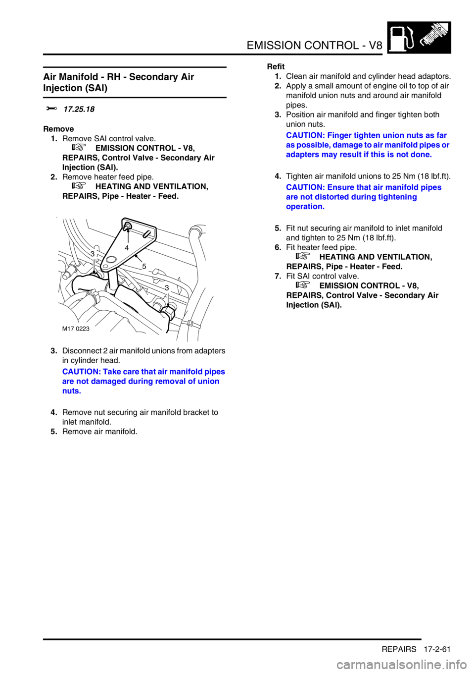
3.Disconnect 2 air manifold unions from adapters
in cylinder head.
CAUTION: Take care that air manifold pipes
are not damaged during removal of union
nuts.
4.Remove nut securing air manifold bracket to
inlet manifold.
5.Remove air manifold.Refit
1.Clean air manifold and cylinder head adaptors.
2.Apply a small amount of engine oil to top of air
manifold union nuts and around air manifold
pipes.
3.Position air manifold and finger tighten both
union nuts.
CAUTION: Finger tighten union nuts as far
as possible, damage to air manifold pipes or
adapters may result if this is not done.
4.Tighten air manifold unions to 25 Nm (18 lbf.ft).
CAUTION: Ensure that air manifold pipes
are not distorted during tightening
operation.
5.Fit nut securing air manifold to inlet manifold
and tighten to 25 Nm (18 lbf.ft).
6.Fit heater feed pipe.
+ HEATING AND VENTILATION,
REPAIRS, Pipe - Heater - Feed.
7.Fit SAI control valve.
+ EMISSION CONTROL - V8,
REPAIRS, Control Valve - Secondary Air
Injection (SAI).
M17 0223
43
3
5
Page 302 of 1529
ENGINE MANAGEMENT SYSTEM - V8
DESCRIPTION AND OPERATION 18-2-3
1Mass air flow/ inlet air temperature sensor
2Fuel injectors
3High tension leads/spark plugs
4Fuel pump relay
5ATC compressor clutch relay/ cooling fan relay
6Throttle position sensor
7Heated oxygen sensor
8Idle air control valve
9Ignition coils
10Engine coolant temperature sensor
11Crankshaft speed and position sensor
12Knock sensor
13Camshaft position sensor
Page 304 of 1529
ENGINE MANAGEMENT SYSTEM - V8
DESCRIPTION AND OPERATION 18-2-5
1Engine control module
2Crankshaft speed and position sensor
3Camshaft position sensor
4Engine coolant temperature sensor
5Mass air flow/ inlet air temperature sensor
6Throttle position sensor
7Heated oxygen sensors
8Fuel injectors
9Idle air control valve
10Fuel pump relay
11EVAP canister
12EVAP canister vent valve
13EVAP canister purge valve
14Fuel tank pressure sensor15Ignition coils
16Knock sensor
17Spark plugs
18High/ Low ratio switch
19Malfunction indication lamp
20Diagnostic connector
21Air temperature control clutch relay
22Air temperature control cooling fan relay
23ATC ECU
24CAN link to EAT
25SLABS ECU
26BCU
27Instrument cluster
28Thermostat monitoring sensor (where fitted)
Page 306 of 1529
ENGINE MANAGEMENT SYSTEM - V8
DESCRIPTION AND OPERATION 18-2-7
The ECM controls the following outputs:
lFuel injectors (1 per cylinder).
lIgnition coils/ high tension leads/ spark plugs.
lFuel pump relay.
lIdle air control valve.
lHeated oxygen sensors.
lEVAP canister purge valve.
lEVAP canister vent solenoid (CVS) valve (where fitted).
lMalfunction Indicator Lamp (MIL)/ service engine soon lamp (where fitted).
lHill descent control (via SLABS interface).
lEVAP system fuel leak detection pump (where fitted)
lSecondary air injection pump (where fitted)
The ECM also interfaces with the following:
lDiagnostics via diagnostic connector with TestBook.
lController Area Network (CAN) link to EAT ECU.
lAir conditioning system.
lSelf Levelling & Anti-lock Braking System (SLABS) ECU.
lImmobilisation system via the body control unit (BCU).
lInstrument cluster.
lCruise control ECU
lActive Cornering Enhancement (ACE) ECU
Page 312 of 1529
ENGINE MANAGEMENT SYSTEM - V8
DESCRIPTION AND OPERATION 18-2-13
Connector 5 (C0638): This connector contains 9 pins and is used to control the ignition system. The ignition coils are
supplied with power and a switching earth completes the circuit.
Pin out details connector C0638
Pin No. Function Signal type Reading
1 Not used - -
2 Ignition , Cylinders 2 and 3 Output Switch to earth
3 Not used - -
4 Not used - -
5 Ignition coil earth Earth 0V
6 Ignition , Cylinders 1 and 6 Output Switch to earth
7 Ignition , Cylinders 4 and 7 Output Switch to earth
8 Ignition , Cylinders 5 and 8 Output Switch to earth
9 Not used - -
Page 335 of 1529

ENGINE MANAGEMENT SYSTEM - V8
18-2-36 DESCRIPTION AND OPERATION
Idle Air Control Valve (IACV) (C0641)
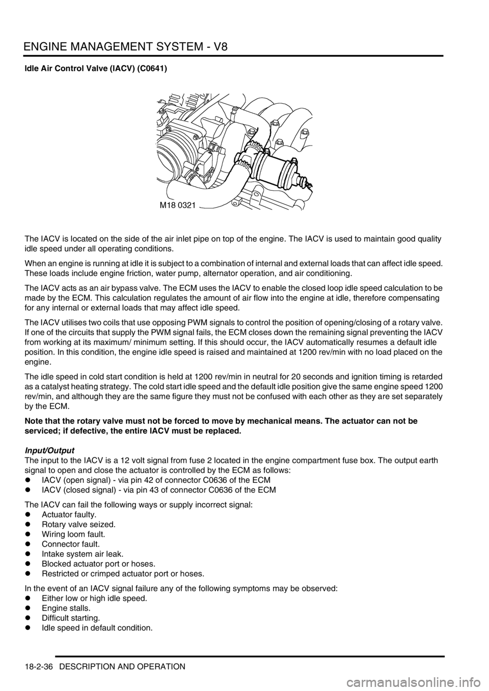
The IACV is located on the side of the air inlet pipe on top of the engine. The IACV is used to maintain good quality
idle speed under all operating conditions.
When an engine is running at idle it is subject to a combination of internal and external loads that can affect idle speed.
These loads include engine friction, water pump, alternator operation, and air conditioning.
The IACV acts as an air bypass valve. The ECM uses the IACV to enable the closed loop idle speed calculation to be
made by the ECM. This calculation regulates the amount of air flow into the engine at idle, therefore compensating
for any internal or external loads that may affect idle speed.
The IACV utilises two coils that use opposing PWM signals to control the position of opening/closing of a rotary valve.
If one of the circuits that supply the PWM signal fails, the ECM closes down the remaining signal preventing the IACV
from working at its maximum/ minimum setting. If this should occur, the IACV automatically resumes a default idle
position. In this condition, the engine idle speed is raised and maintained at 1200 rev/min with no load placed on the
engine.
The idle speed in cold start condition is held at 1200 rev/min in neutral for 20 seconds and ignition timing is retarded
as a catalyst heating strategy. The cold start idle speed and the default idle position give the same engine speed 1200
rev/min, and although they are the same figure they must not be confused with each other as they are set separately
by the ECM.
Note that the rotary valve must not be forced to move by mechanical means. The actuator can not be
serviced; if defective, the entire IACV must be replaced.
Input/Output
The input to the IACV is a 12 volt signal from fuse 2 located in the engine compartment fuse box. The output earth
signal to open and close the actuator is controlled by the ECM as follows:
lIACV (open signal) - via pin 42 of connector C0636 of the ECM
lIACV (closed signal) - via pin 43 of connector C0636 of the ECM
The IACV can fail the following ways or supply incorrect signal:
lActuator faulty.
lRotary valve seized.
lWiring loom fault.
lConnector fault.
lIntake system air leak.
lBlocked actuator port or hoses.
lRestricted or crimped actuator port or hoses.
In the event of an IACV signal failure any of the following symptoms may be observed:
lEither low or high idle speed.
lEngine stalls.
lDifficult starting.
lIdle speed in default condition.
Page 336 of 1529

ENGINE MANAGEMENT SYSTEM - V8
DESCRIPTION AND OPERATION 18-2-37
There are eight IACV diagnostic checks performed by the ECM:
lOutput short circuit to earth – opening coil
lOutput short circuit to battery supply – opening coil
lOutput open circuit – opening coil
lOutput short circuit to earth – closing coil
lOutput short circuit to battery voltage – closing coil
lOutput open circuit – closing coil
lBlocked IACV – rev/min error low (engine speed must be 100 rev/min less than the target speed, engine load
less than 2.5 and the measured air flow more than 10 kg/h less than the expected air flow for a fault condition to
be flagged).
lBlocked IACV – rev/min error high (the engine speed must be more than 180 rev/min greater than the target
speed and the measured air flow more than 10 kg/h greater than the expected air flow for a fault condition to be
flagged).
Should a malfunction of the component occur, the following fault codes may be evident and can be retrieved by
TestBook.
P Code J2012 Description Land Rover Description
P1510 IACV opening coil malfunction Short circuit to battery supply - opening winding
P1513 IACV opening coil malfunction Short circuit to earth - opening winding
P1514 IACV opening coil malfunction Open circuit - opening winding
P1553 IACV closing coil malfunction Short circuit to battery supply - closing winding
P1552 IACV closing coil malfunction Short circuit to earth - closing winding
P1551 IACV closing coil malfunction Open circuit - closing winding
P0505 Idle control system malfunction Blocked IACV - high or low rev/min error
Page 339 of 1529

ENGINE MANAGEMENT SYSTEM - V8
18-2-40 DESCRIPTION AND OPERATION
Ignition coils
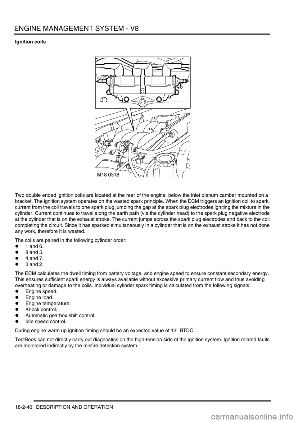
Two double ended ignition coils are located at the rear of the engine, below the inlet plenum camber mounted on a
bracket. The ignition system operates on the wasted spark principle. When the ECM triggers an ignition coil to spark,
current from the coil travels to one spark plug jumping the gap at the spark plug electrodes igniting the mixture in the
cylinder. Current continues to travel along the earth path (via the cylinder head) to the spark plug negative electrode
at the cylinder that is on the exhaust stroke. The current jumps across the spark plug electrodes and back to the coil
completing the circuit. Since it has sparked simultaneously in a cylinder that is on the exhaust stroke it has not done
any work, therefore it is wasted.
The coils are paired in the following cylinder order:
l1 and 6.
l8 and 5.
l4 and 7.
l3 and 2.
The ECM calculates the dwell timing from battery voltage, and engine speed to ensure constant secondary energy.
This ensures sufficient spark energy is always available without excessive primary current flow and thus avoiding
overheating or damage to the coils. Individual cylinder spark timing is calculated from the following signals:
lEngine speed.
lEngine load.
lEngine temperature.
lKnock control.
lAutomatic gearbox shift control.
lIdle speed control.
During engine warm up ignition timing should be an expected value of 12° BTDC.
TestBook can not directly carry out diagnostics on the high-tension side of the ignition system. Ignition related faults
are monitored indirectly by the misfire detection system.