1999 LAND ROVER DISCOVERY air conditioning
[x] Cancel search: air conditioningPage 1229 of 1529
AIR CONDITIONING
82-40REPAIRS
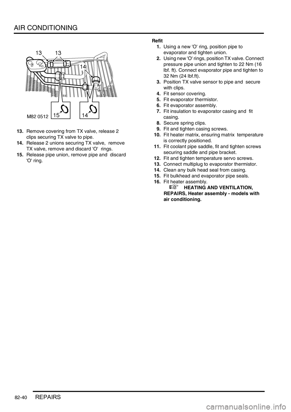
13.Remove covering from TX valve, release 2
clips securing TX valve to pipe.
14.Release 2 unions securing TX valve, remove
TX valve, remove and discard 'O' rings.
15.Release pipe union, remove pipe and discard
'O' ring. Refit
1.Using a new 'O' ring, position pipe to
evaporator and tighten union.
2.Using new 'O' rings, position TX valve. Connect
pressure pipe union and tighten to 22 Nm (16
lbf. ft). Connect evaporator pipe and tighten to
32 Nm (24 lbf.ft).
3.Position TX valve sensor to pipe and secure
with clips.
4.Fit sensor covering.
5.Fit evaporator thermistor.
6.Fit evaporator assembly.
7.Fit insulation to evaporator casing and fit
casing.
8.Secure spring clips.
9.Fit and tighten casing screws.
10.Fit heater matrix, ensuring matrix temperature
is correctly positioned.
11.Fit coolant pipe saddle, fit and tighten screws
securing saddle and pipe bracket.
12.Fit and tighten temperature servo screws.
13.Connect multiplug to evaporator thermistor.
14.Clean any bulk head seal from casing.
15.Fit bulkhead and evaporator pipe seals.
16.Fit heater assembly.
+ HEATING AND VENTILATION,
REPAIRS, Heater assembly - models with
air conditioning.
Page 1230 of 1529
AIR CONDITIONING
REPAIRS 82-41
Expansion valve - (TXV) - rear
$% 82.26.01
Remove
1.Depressurise air conditioning system.
+ AIR CONDITIONING, REFRIGERANT
RECOVERY, RECYCLING AND
RECHARGING, Refrigerant recovery,
recycling and recharging.
2.Remove rear lower trim casing.
+ INTERIOR TRIM COMPONENTS,
REPAIRS, Trim casing - side - loadspace.
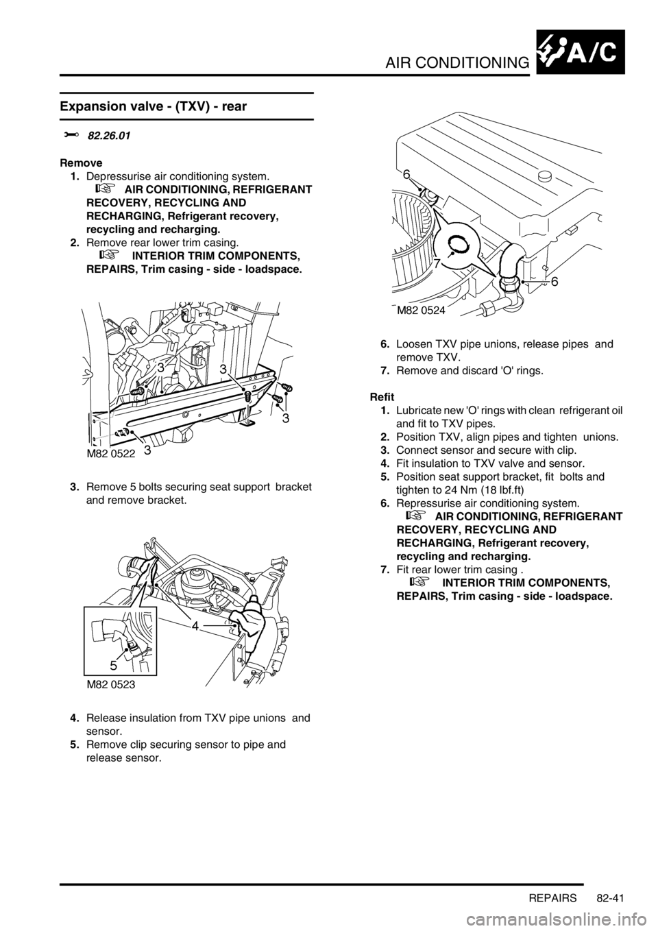
3.Remove 5 bolts securing seat support bracket
and remove bracket.
4.Release insulation from TXV pipe unions and
sensor.
5.Remove clip securing sensor to pipe and
release sensor. 6.Loosen TXV pipe unions, release pipes and
remove TXV.
7.Remove and discard 'O' rings.
Refit
1.Lubricate new 'O' rings with clean refrigerant oil
and fit to TXV pipes.
2.Position TXV, align pipes and tighten unions.
3.Connect sensor and secure with clip.
4.Fit insulation to TXV valve and sensor.
5.Position seat support bracket, fit bolts and
tighten to 24 Nm (18 lbf.ft)
6.Repressurise air conditioning system.
+ AIR CONDITIONING, REFRIGERANT
RECOVERY, RECYCLING AND
RECHARGING, Refrigerant recovery,
recycling and recharging.
7.Fit rear lower trim casing .
+ INTERIOR TRIM COMPONENTS,
REPAIRS, Trim casing - side - loadspace.
Page 1231 of 1529
AIR CONDITIONING
82-42REPAIRS
Evaporator - rear
$% 82.26.20
Remove
1.Remove evaporator assembly.
+ AIR CONDITIONING, REPAIRS,
Evaporator and motor assembly - rear.
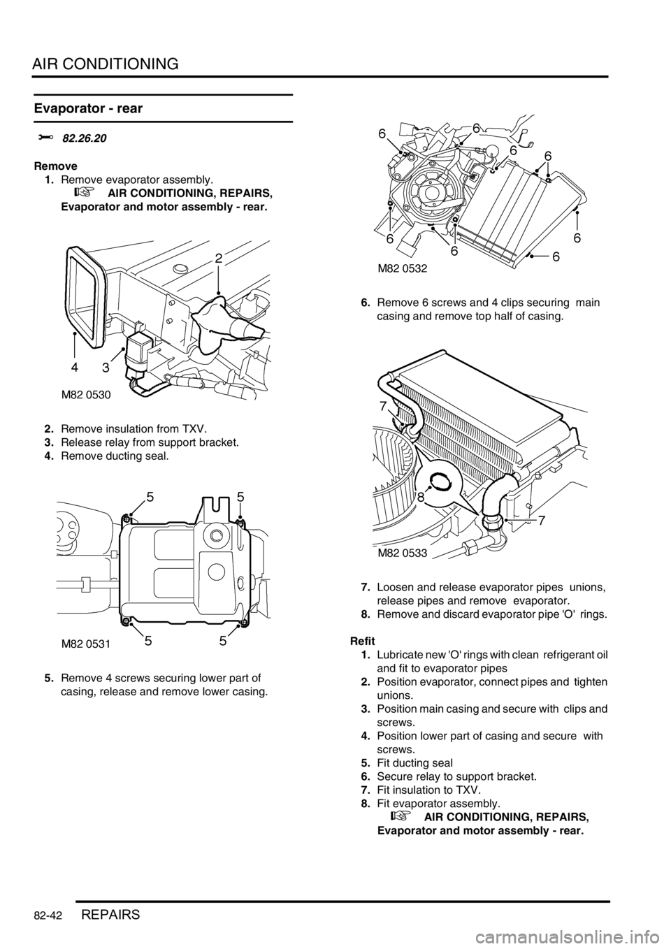
2.Remove insulation from TXV.
3.Release relay from support bracket.
4.Remove ducting seal.
5.Remove 4 screws securing lower part of
casing, release and remove lower casing. 6.Remove 6 screws and 4 clips securing main
casing and remove top half of casing.
7.Loosen and release evaporator pipes unions,
release pipes and remove evaporator.
8.Remove and discard evaporator pipe 'O' rings.
Refit
1.Lubricate new 'O' rings with clean refrigerant oil
and fit to evaporator pipes
2.Position evaporator, connect pipes and tighten
unions.
3.Position main casing and secure with clips and
screws.
4.Position lower part of casing and secure with
screws.
5.Fit ducting seal
6.Secure relay to support bracket.
7.Fit insulation to TXV.
8.Fit evaporator assembly.
+ AIR CONDITIONING, REPAIRS,
Evaporator and motor assembly - rear.
Page 1232 of 1529
AIR CONDITIONING
REPAIRS 82-43
Evaporator and motor assembly - rear
$% 82.26.21
Remove
1.Depressurise air conditioning system.
+ AIR CONDITIONING, REFRIGERANT
RECOVERY, RECYCLING AND
RECHARGING, Refrigerant recovery,
recycling and recharging.
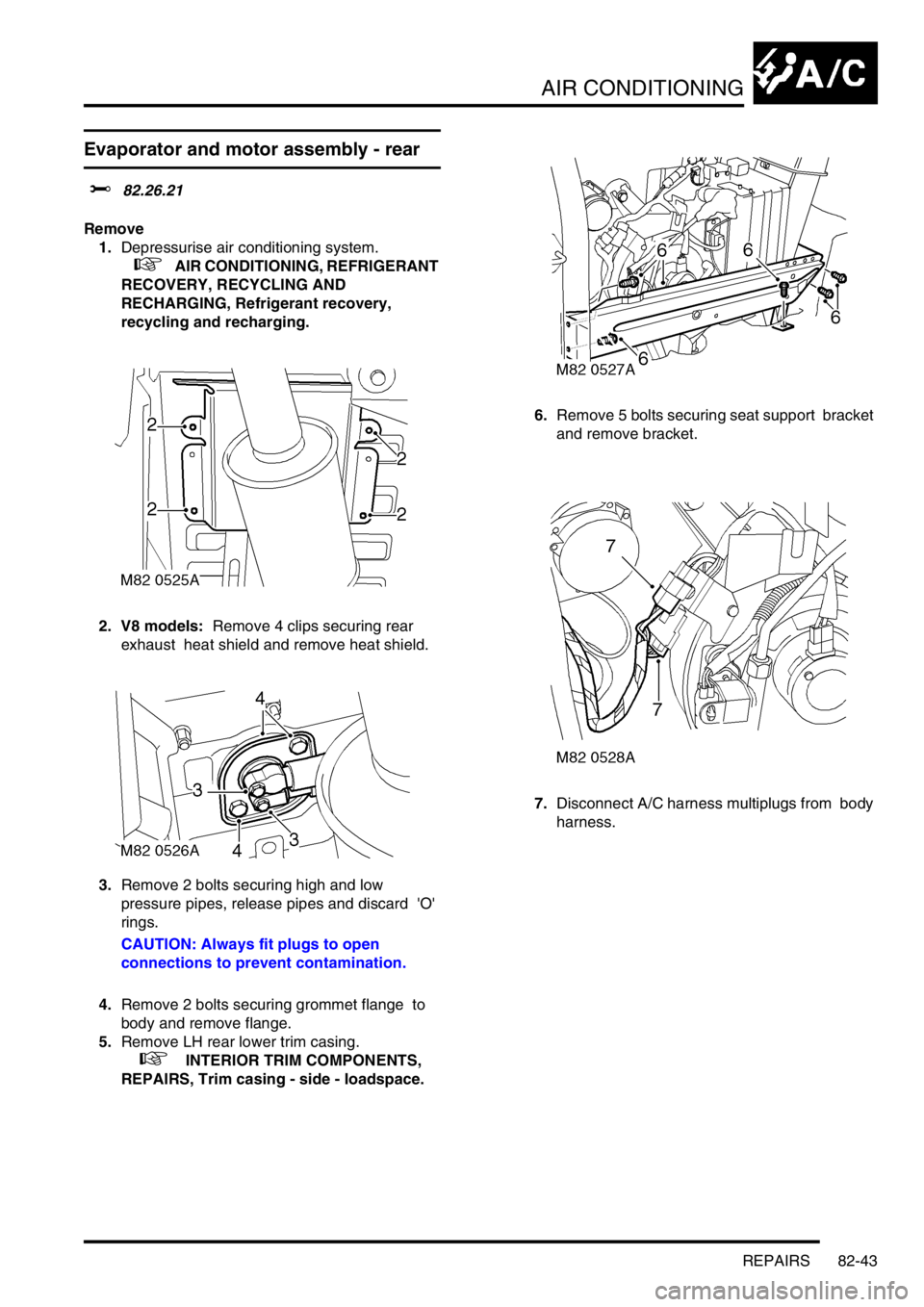
2. V8 models: Remove 4 clips securing rear
exhaust heat shield and remove heat shield.
3.Remove 2 bolts securing high and low
pressure pipes, release pipes and discard 'O'
rings.
CAUTION: Always fit plugs to open
connections to prevent contamination.
4.Remove 2 bolts securing grommet flange to
body and remove flange.
5.Remove LH rear lower trim casing.
+ INTERIOR TRIM COMPONENTS,
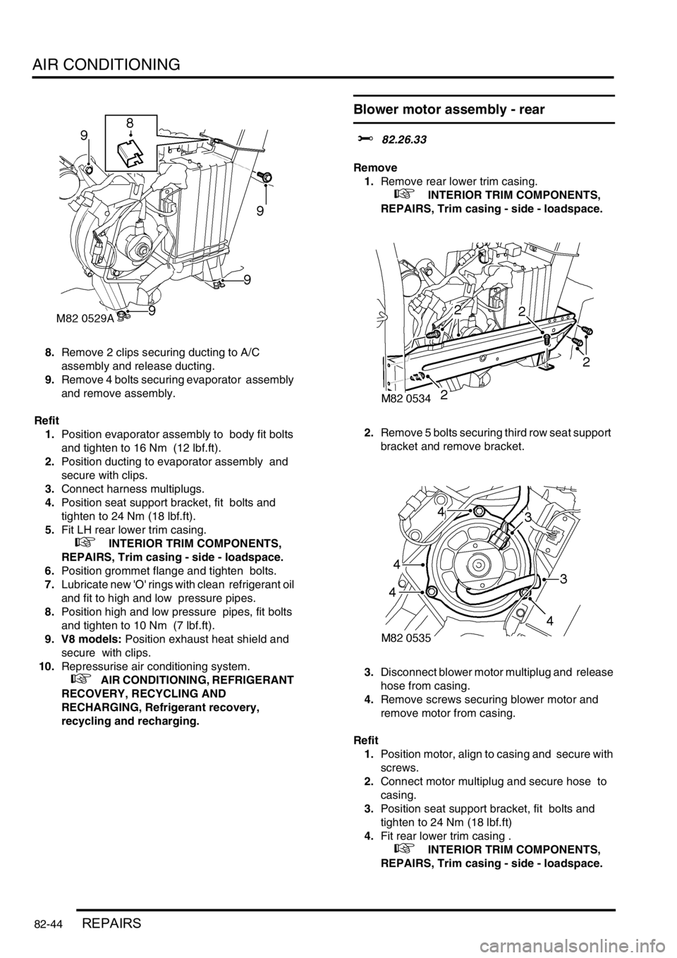
REPAIRS, Trim casing - side - loadspace.6.Remove 5 bolts securing seat support bracket
and remove bracket.
7.Disconnect A/C harness multiplugs from body
harness.
Page 1233 of 1529
AIR CONDITIONING
82-44REPAIRS
8.Remove 2 clips securing ducting to A/C
assembly and release ducting.
9.Remove 4 bolts securing evaporator assembly
and remove assembly.
Refit
1.Position evaporator assembly to body fit bolts
and tighten to 16 Nm (12 lbf.ft).
2.Position ducting to evaporator assembly and
secure with clips.
3.Connect harness multiplugs.
4.Position seat support bracket, fit bolts and
tighten to 24 Nm (18 lbf.ft).
5.Fit LH rear lower trim casing.
+ INTERIOR TRIM COMPONENTS,
REPAIRS, Trim casing - side - loadspace.
6.Position grommet flange and tighten bolts.
7.Lubricate new 'O' rings with clean refrigerant oil
and fit to high and low pressure pipes.
8.Position high and low pressure pipes, fit bolts
and tighten to 10 Nm (7 lbf.ft).
9. V8 models: Position exhaust heat shield and
secure with clips.
10.Repressurise air conditioning system.
+ AIR CONDITIONING, REFRIGERANT
RECOVERY, RECYCLING AND
RECHARGING, Refrigerant recovery,
recycling and recharging.
Blower motor assembly - rear
$% 82.26.33
Remove
1.Remove rear lower trim casing.
+ INTERIOR TRIM COMPONENTS,
REPAIRS, Trim casing - side - loadspace.
2.Remove 5 bolts securing third row seat support
bracket and remove bracket.
3.Disconnect blower motor multiplug and release
hose from casing.
4.Remove screws securing blower motor and
remove motor from casing.
Refit
1.Position motor, align to casing and secure with
screws.
2.Connect motor multiplug and secure hose to
casing.
3.Position seat support bracket, fit bolts and
tighten to 24 Nm (18 lbf.ft)
4.Fit rear lower trim casing .
+ INTERIOR TRIM COMPONENTS,
REPAIRS, Trim casing - side - loadspace.
Page 1234 of 1529
AIR CONDITIONING
REPAIRS 82-45
Resistor - blower motor
$% 82.26.48
Remove
1.Remove rear lower trim casing.
+ INTERIOR TRIM COMPONENTS,
REPAIRS, Trim casing - side - loadspace.
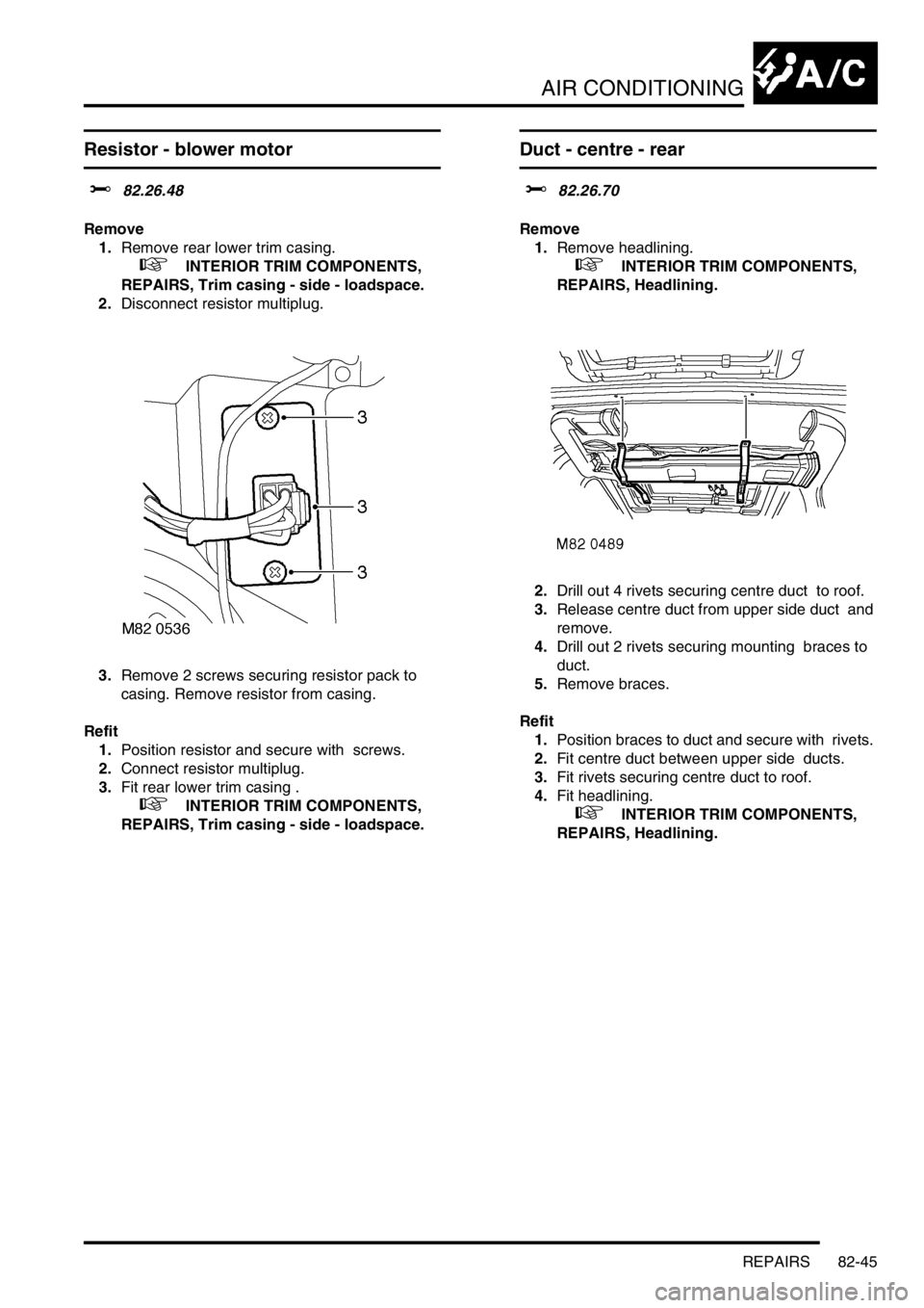
2.Disconnect resistor multiplug.
3.Remove 2 screws securing resistor pack to
casing. Remove resistor from casing.
Refit
1.Position resistor and secure with screws.
2.Connect resistor multiplug.
3.Fit rear lower trim casing .
+ INTERIOR TRIM COMPONENTS,
REPAIRS, Trim casing - side - loadspace.
Duct - centre - rear
$% 82.26.70
Remove
1.Remove headlining.
+ INTERIOR TRIM COMPONENTS,
REPAIRS, Headlining.
2.Drill out 4 rivets securing centre duct to roof.
3.Release centre duct from upper side duct and
remove.
4.Drill out 2 rivets securing mounting braces to
duct.
5.Remove braces.
Refit
1.Position braces to duct and secure with rivets.
2.Fit centre duct between upper side ducts.
3.Fit rivets securing centre duct to roof.
4.Fit headlining.
+ INTERIOR TRIM COMPONENTS,
REPAIRS, Headlining.
Page 1304 of 1529

BODY CONTROL UNIT
DESCRIPTION AND OPERATION 86-3-17
The existence of an intermediate state causes a fault code to be detected by the BCU. To reduce the chances of the
fault condition occurring while changing selector lever position, the inputs are debounced and only considered valid
when they have existed for at least 33 ms.
Transmission neutral selector
The transmission neutral sensor provides an earth signal to the BCU when the transfer box is in neutral. The earth
signal causes the BCU to operate an audible warning when the transfer box is in neutral with the ignition switched on.
+ TRANSFER BOX - LT230SE, DESCRIPTION AND OPERATION, Description.
Self levelling suspension and ABS
The BCU communicates with the SLABS ECU for several functions:
lAn output is provided from the SLABS ECU to the BCU to provide the logic conditions for issuing the SLS audible
warning.
lThe BCU receives an input from the SLABS ECU relating to the raise/ lower command from the remote handset.
+ REAR SUSPENSION, DESCRIPTION AND OPERATION, Description - SLS.
Hill descent control
The BCU provides an output signal to the SLABS ECU for automatic transmission in neutral for HDC control. The
BCU checks the status of the ignition and 'gearbox state' inputs and provides a 'Neutral selected' output. If the ignition
is on and 'gearbox state' is Neutral, the 'Neutral selected' output is on, otherwise 'Neutral selected' is off.
+ BRAKES, DESCRIPTION AND OPERATION, Description.
Heated screens
The Heated Front Screen (HFS) is fitted for some market destinations and is operated from a non-latching switch
located on the instrument pack cowl. The BCU will only allow the heated front screen to operate when the engine is
running and controls the time-out period for switching the circuit off.
The heated front screen operation can also be controlled from the Automatic Temperature Control (ATC) ECU on
vehicles fitted with air conditioning.
The heated rear window will only function when the engine is running, and is operated by a non-latching switch on the
instrument pack cowl. The heated rear window can also be operated by the ATC ECU on vehicles fitted with air
conditioning.
Interior courtesy lamps
The BCU controls the operation of the interior courtesy lamps. The courtesy lamps are situated in the front, mid and
rear areas of the headlining.
Fuel flap actuator
The BCU provides an earth path to the fuel flap release solenoid to allow the fuel filler flap to be opened. This is only
allowed if the alarm system is not set and all other conditions have been satisfied. The fuel flap release switch is
located in the fascia switch pack on vehicles up to 2003 model year or in the instrument pack binacle on vehicles from
2003 model year. The switch receives a voltage supply from the passenger compartment fuse box.
Page 1310 of 1529

BODY CONTROL UNIT
DESCRIPTION AND OPERATION 86-3-23
A timeout function is included which allows the windows and sunroofs to be operated for a period of 44 ± 1 seconds
after the ignition key has been removed from the ignition switch. The timeout function will be cancelled if the BCU
detects the following conditions:
lThe driver's door has been closed after the ignition has been switched off.
lAny door open after the ignition is switched off.
The preconditions are programmed into the BCU dependent on market specification.
The BCU does not directly control rear window operation, but it can request the IDM to remove the power feed to the
rear windows. The IDM enables power supply to be provided to the rear lift relay in the passenger fuse box. When the
relay coil is energised the relay contacts close and power is applied to the rear window motor. If the window lift
isolation switch located in the centre console is latched out, the earth path from the LH and RH rear door window
switches is broken and operation of the rear window motors through the use of the rear window switches is prevented.
Rear window operation using the console switches is not affected by the isolation switch.
In the event of a communications link failure occurring while rear window enable is on, the relay remains on until the
ignition switch is turned to the off position.
Heated screens
The heated screen time-outs and logical operations are controlled by the BCU.
Heated front screen
The BCU provides an output to the heated front screen relay and a 'heated front screen active signal' for the heated
front screen warning lamp. The BCU uses the status of the following inputs to determine the appropriate logical
operations for this feature:
lIgnition state.
lEngine running (link from instrument pack).
lHeated front screen selected (non-latched button pressed).
If the ignition switch is not in position II, or the engine running signal is OFF, the heated front screen will not be active.
The heated front screen operation period and voltage supply is controlled by the BCU. The BCU receives a voltage
supply feed from the engine compartment fuse box and an ignition switched supply through a fuse in the passenger
compartment fuse box. When the heated front screen switch is operated, it completes a path to earth, signalling a
request for heated screen operation to the BCU. The BCU then supplies a feed to the heated front screen switch to
light the switch indicator, and earths the supply from the coil of the heated screen relay to turn the heated front screen
on. The BCU maintains a supply for a predetermined time (5 minutes), then opens the earth path after the time out
period to turn the heated screen off. During the timeout period, if the heated front screen switch is pressed a second
time, the circuit is also interrupted to turn off the supply to the heated front screen.
On vehicles fitted with air conditioning, the heated front screen is also operated by the ATC ECU when DEF (defrost)
is selected. In this case the ATC ECU provides the trigger signal to the BCU to turn the heated front screen circuit on
or, if it is already on, to re-start the time out period.
+ AIR CONDITIONING, DESCRIPTION AND OPERATION, Description.
In the event of a communications link failure occurring while the heated front screen relay is on, the relay and lamp
will remain on until the ignition switch is turned off or the time-out period elapses or the heated front screen switch is
pressed.
Heated rear window
The heated rear window will only function when the engine is running, and is operated by a non-latching switch on the
instrument pack cowl.
The BCU provides a 'heated rear window enable output' and a 'heated rear window active warning lamp signal' based
on the logic status of the following inputs:
lIgnition state.
lEngine running (link from instrument pack).
lHeated rear window selected (non-latched button pressed).
If the ignition switch is not in position II, or the engine running signal is OFF, the heated rear window will not be active.