1999 LAND ROVER DISCOVERY air conditioning
[x] Cancel search: air conditioningPage 1311 of 1529

BODY CONTROL UNIT
86-3-24 DESCRIPTION AND OPERATION
The heated rear window operation period and voltage supply is controlled by the BCU. The BCU receives a voltage
supply feed from the engine compartment fuse box and an ignition switched supply through a fuse in the passenger
compartment fuse box. When the heated rear window switch is operated, it completes a path to earth, signalling a
request for heated rear window operation to the BCU. The BCU then supplies a feed to the heated rear window switch
to light the switch indicator, and earths the supply from the coil of the heated rear window relay via the IDM to turn the
heated rear window elements on. The BCU maintains a supply for a predetermined time (15 minutes), then opens the
earth path after the time-out period to turn the heated rear window operation off. If the heated rear window switch is
pressed a second time, the circuit is also interrupted to turn off the supply to the heated front screen.
On vehicles fitted with air conditioning, the heated rear window is also operated by the ATC ECU when DEF (defrost)
is selected. In this case the ATC ECU provides the trigger signal to the BCU to turn the heated rear window circuit on
or, if it is already on, to re-start the time out period.
+ AIR CONDITIONING, DESCRIPTION AND OPERATION, Description.
In the event of a communications link failure occurring while the heated rear window enable is on, the relay and lamp
will be de-activated.
Wipers and washers
Front and rear wash/ wipe operations are controlled by the BCU via the IDM.
Front wipers and washers
When front intermittent wipe is selected using the wiper switch on the column stalk, the BCU signals the IDM to
operate the wiper motor. The IDM then supplies a voltage to the normal speed winding of the wiper motor for a period
of no longer than 500 ms. The timed feed ensures the wiper motor operates, but does not complete more than a single
wipe of the screen. The BCU checks the position of the delay switch to determine the delay period which should be
utilised for the intermittent wipe operation. The delay period of the front intermittent wipe is maintained until the wiper
switch is moved to the off, normal or fast speed position, or the delay period is changed.
When front intermittent wipe is selected, a delay period of 500 ms will be incurred before the wipers operate. This
delay prevents the occurrence of a wipe action when the wiper switch is changed to the off position from the normal
or fast modes of operation.
To enable the front intermittent wipe facility, the BCU checks the state of the following inputs:
lIgnition state.
lFront intermittent wiper switch.
lFront intermittent wiper rate.
If the ignition switch is in the off or crank position, the front wipers are not active and the front wiper enable output is
switched off.
If the option to initiate a wipe action in addition to a front screen wash action has been configured in the BCU, the
wipers will operate 400 ms after the washer pump becomes active. If the washer switch is released within 400 ms,
the wipers will not be activated. If a washer switch is pressed for longer than 400 ms, the BCU will operate the wipers
after an initial delay of 400 ms, and will continue to operate for as long as the washer switch is depressed plus an
additional 4 seconds.
The front wash/ wipe programme can be configured to operate in one of two ways:
lOption 1 – normal.
lOption 2 – no wipe.
The BCU checks for the following inputs:
lIgnition state.
lFront washer pump switch.
The BCU can provide the following wash / wipe outputs depending on the logic states prevailing:
lFront wiper enable.
lFront wash/ wipe in progress flag.
In the event of a communications link failure occurring while the front wash/ wipe programme is in operation, the front
wiper enable output is switched off.
Page 1408 of 1529
HARNESSES
REPAIRS 86-7-3
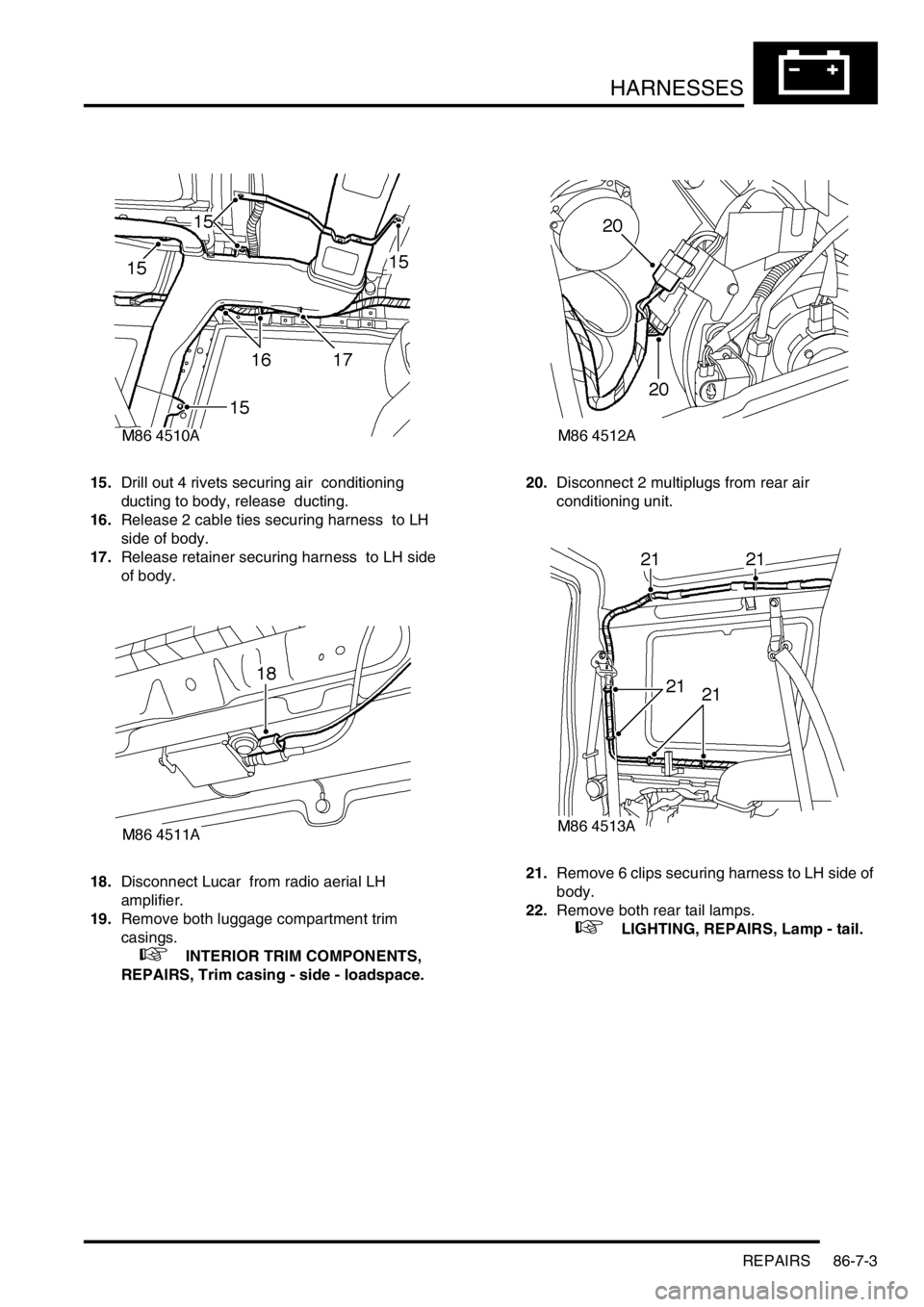
15.Drill out 4 rivets securing air conditioning
ducting to body, release ducting.
16.Release 2 cable ties securing harness to LH
side of body.
17.Release retainer securing harness to LH side
of body.
18.Disconnect Lucar from radio aerial LH
amplifier.
19.Remove both luggage compartment trim
casings.
+ INTERIOR TRIM COMPONENTS,
REPAIRS, Trim casing - side - loadspace.20.Disconnect 2 multiplugs from rear air
conditioning unit.
21.Remove 6 clips securing harness to LH side of
body.
22.Remove both rear tail lamps.
+ LIGHTING, REPAIRS, Lamp - tail.
Page 1409 of 1529
HARNESSES
86-7-4 REPAIRS
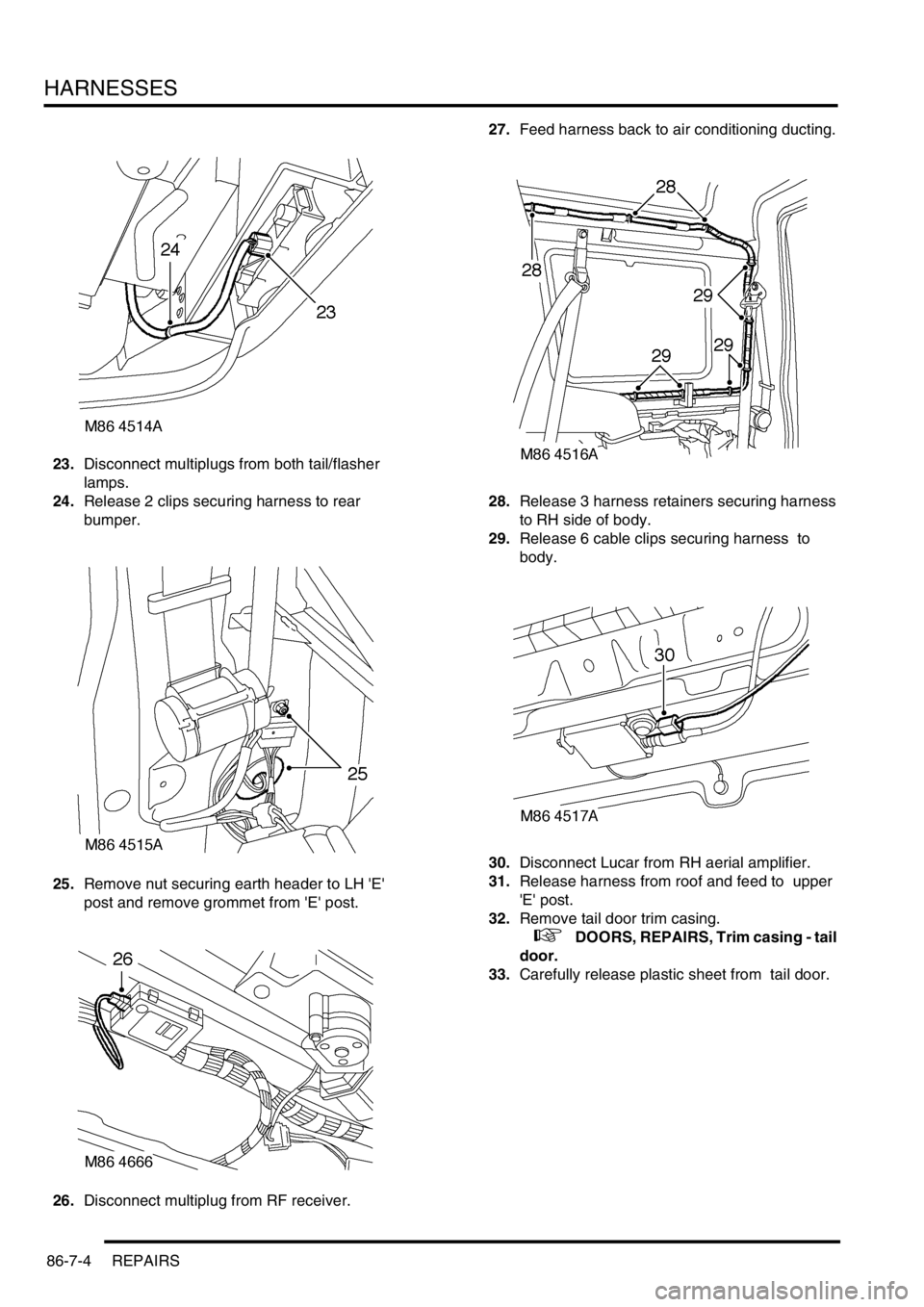
23.Disconnect multiplugs from both tail/flasher
lamps.
24.Release 2 clips securing harness to rear
bumper.
25.Remove nut securing earth header to LH 'E'
post and remove grommet from 'E' post.
26.Disconnect multiplug from RF receiver.27.Feed harness back to air conditioning ducting.
28.Release 3 harness retainers securing harness
to RH side of body.
29.Release 6 cable clips securing harness to
body.
30.Disconnect Lucar from RH aerial amplifier.
31.Release harness from roof and feed to upper
'E' post.
32.Remove tail door trim casing.
+ DOORS, REPAIRS, Trim casing - tail
door.
33.Carefully release plastic sheet from tail door.
Page 1411 of 1529
HARNESSES
86-7-6 REPAIRS
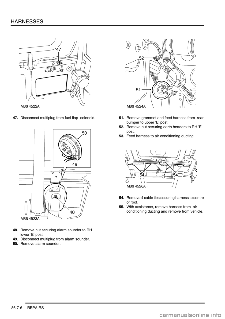
47.Disconnect multiplug from fuel flap solenoid.
48.Remove nut securing alarm sounder to RH
lower 'E' post.
49.Disconnect multiplug from alarm sounder.
50.Remove alarm sounder. 51.Remove grommet and feed harness from rear
bumper to upper 'E' post.
52.Remove nut securing earth headers to RH 'E'
post.
53.Feed harness to air conditioning ducting.
54.Remove 4 cable ties securing harness to centre
of roof.
55.With assistance, remove harness from air
conditioning ducting and remove from vehicle.
Page 1412 of 1529

HARNESSES
REPAIRS 86-7-7
Refit
1.With assistance, position harness to air
conditioning ducting and secure with cable ties.
2.Secure harness to sunroof harness with cable
clips.
3.Connect multiplug to RF receiver.
4.Feed harness to LH and RH upper 'E' posts.
5.Feed harness through 'E' post to tail lamp and
rear bumper and secure with grommet.
6.Connect multiplug to fuel flap solenoid and
alarm sounder.
7.Position alarm sounder to rear quarter and
secure with nut to 9 Nm (7 lbf.ft).
8.Position both RH earth header to 'E' post and
tighten nut to 10 Nm (7 lbf.ft).
9.Feed tail door harness through 'E' post and
secure with grommet.
10.Position harness sleeve to outer edge of door
and pull harness through door.
11.Secure harness to tail door with clips.
12.Connect washer tube to rear of wiper arm.
13.Remove tape from draw string and secure to
CHMSL harness.
14.Draw harness through tail door and connect
Lucars to CHMSL.
15.Fit CHMSL cover and secure with screws.
16.Connect multiplug to door lock switch.
17.Connect Lucars to HRW.
18.Connect multiplug to rear wiper motor.
19.Connect multiplug to door latch.
20.Fit plastic sheet to tail door, ensuring it aligns
with witness marks.
21.Fit tail door trim casing.
+ DOORS, REPAIRS, Trim casing - tail
door.
22.Connect Lucar to radio aerial RH amplifier.
23.Secure harness to RH side of body with clips
and retainers.
24.Position both LH earth header to 'E' post and
tighten nut to 10 Nm (7 lbf.ft).
25.Connect multiplugs to both tail/flasher lamps
and secure harness to bumper with clips.
26.Fit both rear tail lamps.
+ LIGHTING, REPAIRS, Lamp - tail.
27.Secure harness to rear LH side of body with 6
cable clips.
28.Connect 2 Lucars to rear air conditioning unit.
29.Fit both luggage compartment trim casings.
+ INTERIOR TRIM COMPONENTS,
REPAIRS, Trim casing - side - loadspace.
30.Feed harness into position for rear interior light.
31.Connect Lucar to radio aerial LH amplifier.
32.Secure harness to body with cable ties clips
and retainers.
33.Secure air conditioning ducting to body with
rivets.
34.Feed harness to LH lower 'A' post. 35.Secure harness to LH side of body with cable
tie clips and retainers.
36.Connect and secure multiplugs to lower LH 'A'
post.
37.Feed harness through roof to centre.
38.Secure harness behind bonnet release cable.
39.Connect rear washer pipe at lower 'A' post and
secure with clip.
40.Secure harness to roof with clips.
41.Connect multiplug to interior mirror, ARC
accelerometer.
42.Position sound deadening panels and secure
with clips.
43.Fit headlining.
+ INTERIOR TRIM COMPONENTS,
REPAIRS, Headlining.
44.Fit fascia panel.
+ INTERIOR TRIM COMPONENTS,
REPAIRS, Fascia.
Page 1414 of 1529

HARNESSES
REPAIRS 86-7-9
6.Disconnect air conditioning compressor
multiplug.
7.Remove 2 nuts securing alternator cables and
release cables. 8.Disconnect coolant temperature sensor
multiplug.
9.Release 2 harness clips from coolant rail.
10.Remove nut securing engine harness positive
lead to battery, release lead and position
aside.
Page 1420 of 1529
HARNESSES
REPAIRS 86-7-15
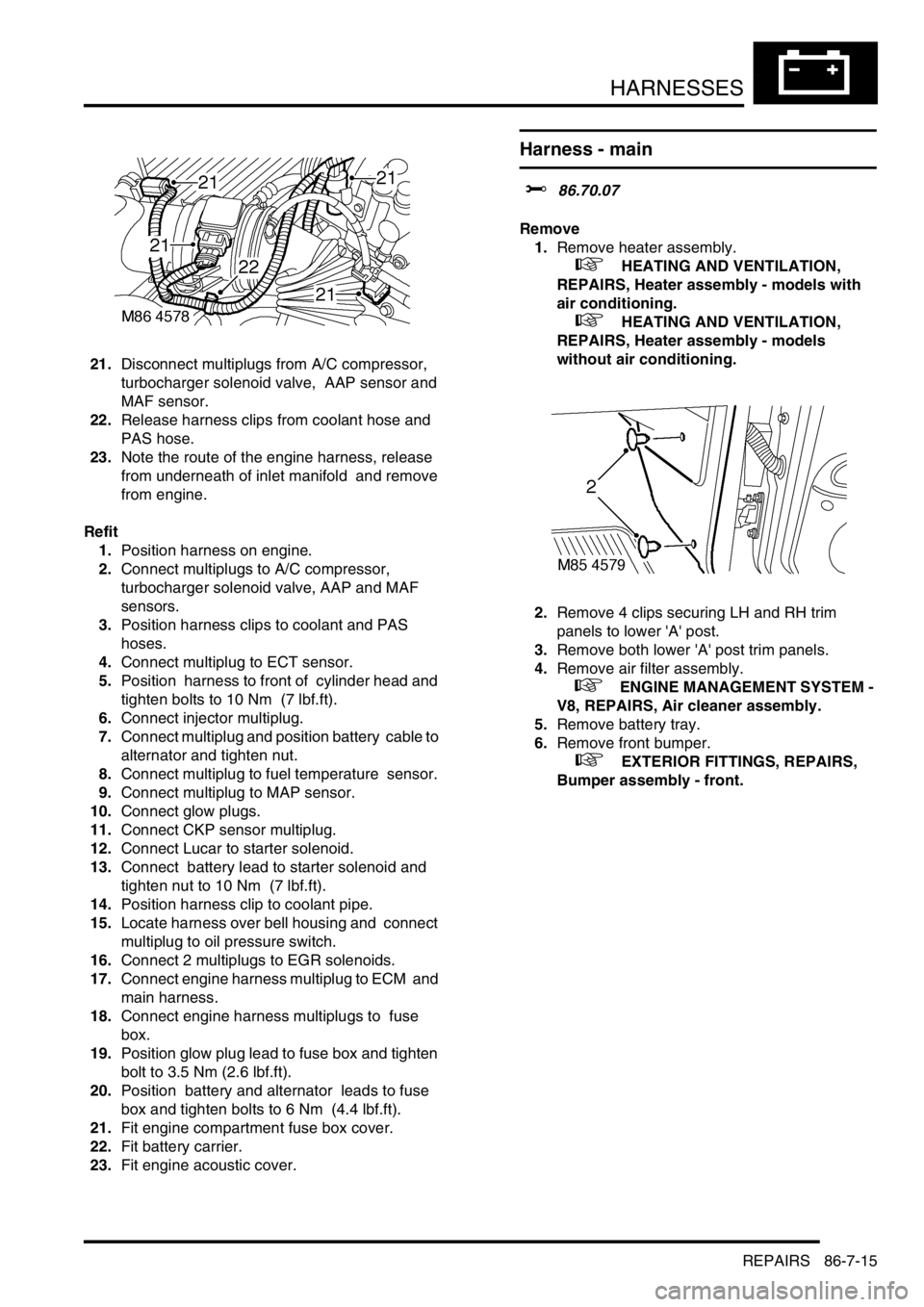
21.Disconnect multiplugs from A/C compressor,
turbocharger solenoid valve, AAP sensor and
MAF sensor.
22.Release harness clips from coolant hose and
PAS hose.
23.Note the route of the engine harness, release
from underneath of inlet manifold and remove
from engine.
Refit
1.Position harness on engine.
2.Connect multiplugs to A/C compressor,
turbocharger solenoid valve, AAP and MAF
sensors.
3.Position harness clips to coolant and PAS
hoses.
4.Connect multiplug to ECT sensor.
5.Position harness to front of cylinder head and
tighten bolts to 10 Nm (7 lbf.ft).
6.Connect injector multiplug.
7.Connect multiplug and position battery cable to
alternator and tighten nut.
8.Connect multiplug to fuel temperature sensor.
9.Connect multiplug to MAP sensor.
10.Connect glow plugs.
11.Connect CKP sensor multiplug.
12.Connect Lucar to starter solenoid.
13.Connect battery lead to starter solenoid and
tighten nut to 10 Nm (7 lbf.ft).
14.Position harness clip to coolant pipe.
15.Locate harness over bell housing and connect
multiplug to oil pressure switch.
16.Connect 2 multiplugs to EGR solenoids.
17.Connect engine harness multiplug to ECM and
main harness.
18.Connect engine harness multiplugs to fuse
box.
19.Position glow plug lead to fuse box and tighten
bolt to 3.5 Nm (2.6 lbf.ft).
20.Position battery and alternator leads to fuse
box and tighten bolts to 6 Nm (4.4 lbf.ft).
21.Fit engine compartment fuse box cover.
22.Fit battery carrier.
23.Fit engine acoustic cover.
Harness - main
$% 86.70.07
Remove
1.Remove heater assembly.
+ HEATING AND VENTILATION,
REPAIRS, Heater assembly - models with
air conditioning.
+ HEATING AND VENTILATION,
REPAIRS, Heater assembly - models
without air conditioning.
2.Remove 4 clips securing LH and RH trim
panels to lower 'A' post.
3.Remove both lower 'A' post trim panels.
4.Remove air filter assembly.
+ ENGINE MANAGEMENT SYSTEM -
V8, REPAIRS, Air cleaner assembly.
5.Remove battery tray.
6.Remove front bumper.
+ EXTERIOR FITTINGS, REPAIRS,
Bumper assembly - front.
Page 1433 of 1529
HARNESSES
86-7-28 REPAIRS
50.Feed harness through to front panel.
51.Secure fog lamp multiplug.
52.Connect headlamp level motor, headlamp and
side lamp multiplugs.
53.Fit indicator lamp.
+ LIGHTING, REPAIRS, Lamp - front
repeater - up to 03MY.
54.Secure harness to RH front panel.
55.Connect cooling fan and horn multiplug.
56.Secure harness to lower support rail.
57.Connect receiver drier and air temperature
sensor multiplugs.
58.Fit front bumper.
+ EXTERIOR FITTINGS, REPAIRS,
Bumper assembly - front.
59.Fit battery tray.
60.Fit air filter assembly.
+ ENGINE MANAGEMENT SYSTEM -
V8, REPAIRS, Air cleaner assembly.
61.Position both lower 'A' post trims and secure
with studs.
62.Fit heater assembly.
+ HEATING AND VENTILATION,
REPAIRS, Heater assembly - models with
air conditioning.
+ HEATING AND VENTILATION,
REPAIRS, Heater assembly - models
without air conditioning.
Harness - main - DVD unit
$% 86.70.25
Remove
1.Remove battery cover and disconnect the
battery earth lead.
2.Remove CD switch box.
+ IN CAR ENTERTAINMENT,
REPAIRS, Switch box - CD/DVD player.
3.Remove DVD player unit.
+ IN CAR ENTERTAINMENT,
REPAIRS, DVD screen/player unit.
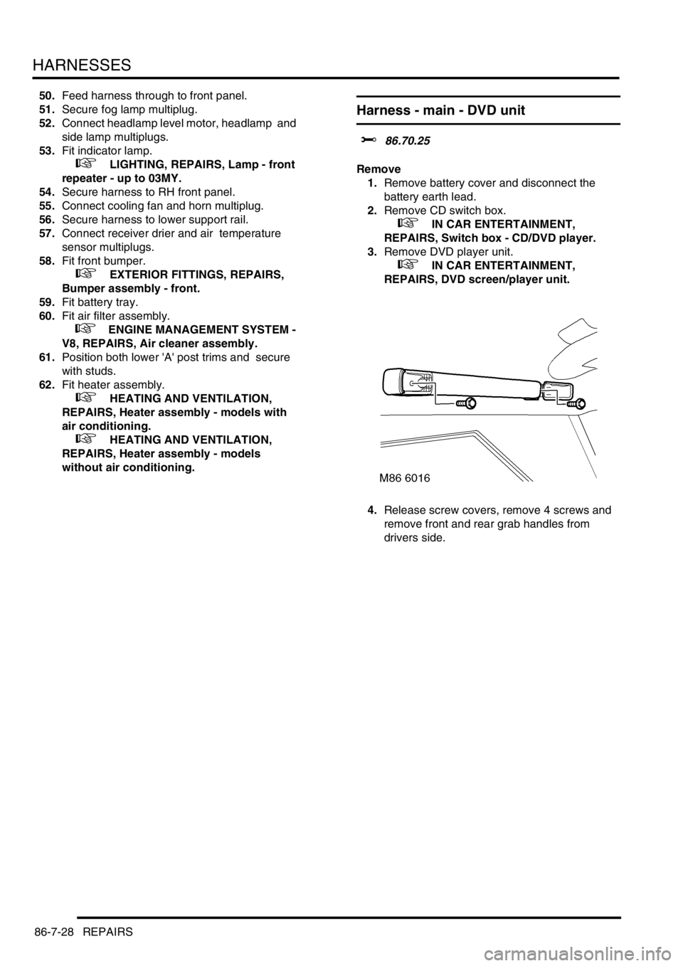
4.Release screw covers, remove 4 screws and
remove front and rear grab handles from
drivers side.