1999 LAND ROVER DEFENDER half shaft
[x] Cancel search: half shaftPage 24 of 667

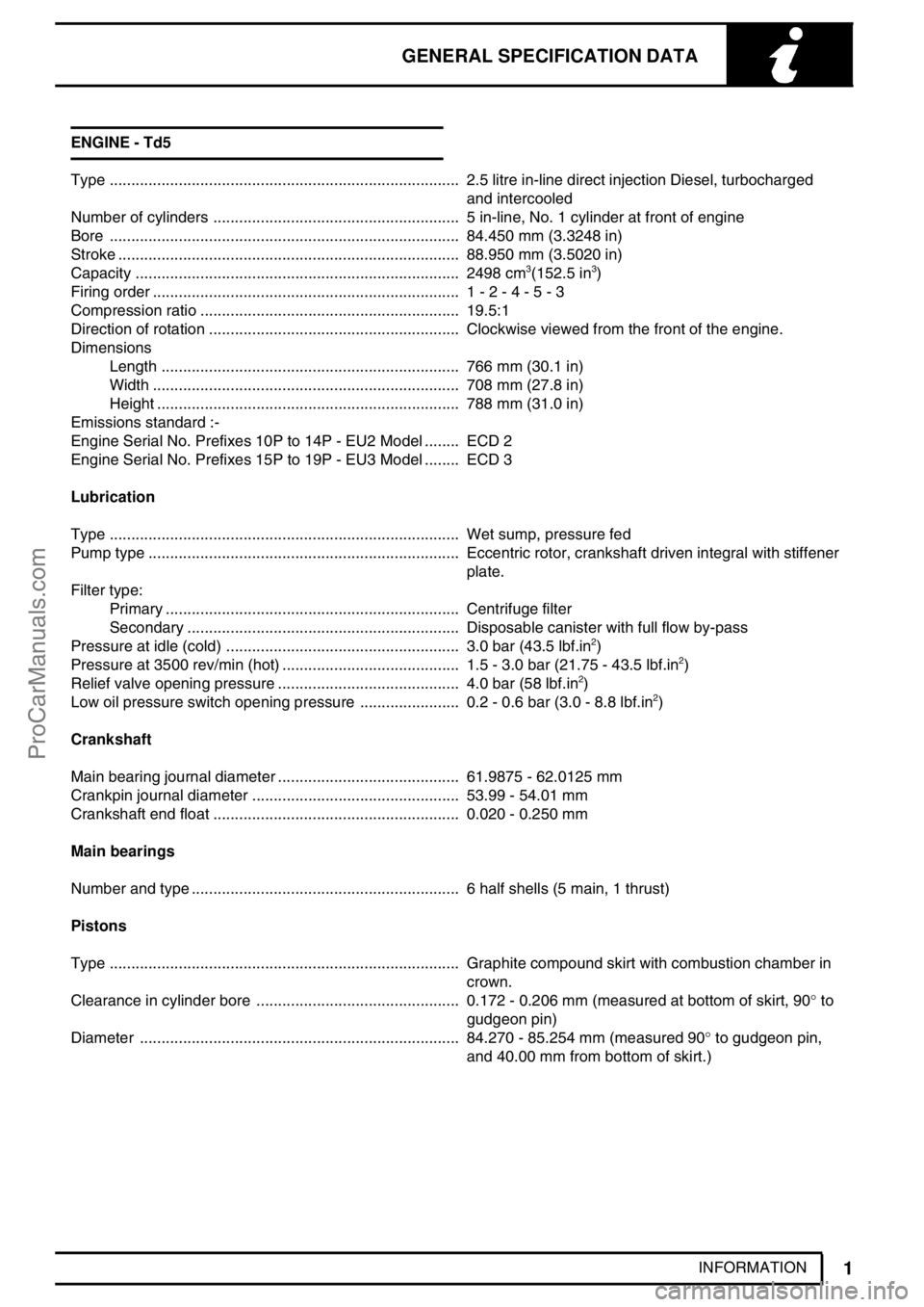
GENERAL SPECIFICATION DATA
1
INFORMATION ENGINE - Td5
Type 2.5 litre in-line direct injection Diesel, turbocharged.................................................................................
and intercooled
Number of cylinders 5 in-line, No. 1 cylinder at front of engine.........................................................
Bore 84.450 mm (3.3248 in).................................................................................
Stroke 88.950 mm (3.5020 in)...............................................................................
Capacity 2498 cm
3(152.5 in3) ...........................................................................
Firing order 1 - 2 - 4 - 5 - 3.......................................................................
Compression ratio 19.5:1............................................................
Direction of rotation Clockwise viewed from the front of the engine...........................................................
Dimensions
Length 766 mm (30.1 in).....................................................................
Width 708 mm (27.8 in).......................................................................
Height 788 mm (31.0 in)......................................................................
Emissions standard :-
Engine Serial No. Prefixes 10P to 14P - EU2 Model ECD 2........
Engine Serial No. Prefixes 15P to 19P - EU3 Model ECD 3........
Lubrication
Type Wet sump, pressure fed.................................................................................
Pump type Eccentric rotor, crankshaft driven integral with stiffener........................................................................
plate.
Filter type:
Primary Centrifuge filter....................................................................
Secondary Disposable canister with full flow by-pass...............................................................
Pressure at idle (cold) 3.0 bar (43.5 lbf.in
2) ......................................................
Pressure at 3500 rev/min (hot) 1.5 - 3.0 bar (21.75 - 43.5 lbf.in2) .........................................
Relief valve opening pressure 4.0 bar (58 lbf.in2) ..........................................
Low oil pressure switch opening pressure 0.2 - 0.6 bar (3.0 - 8.8 lbf.in2) .......................
Crankshaft
Main bearing journal diameter 61.9875 - 62.0125 mm..........................................
Crankpin journal diameter 53.99 - 54.01 mm................................................
Crankshaft end float 0.020 - 0.250 mm.........................................................
Main bearings
Number and type 6 half shells (5 main, 1 thrust)..............................................................
Pistons
Type Graphite compound skirt with combustion chamber in.................................................................................
crown.
Clearance in cylinder bore 0.172 - 0.206 mm (measured at bottom of skirt, 90°to ...............................................
gudgeon pin)
Diameter 84.270 - 85.254 mm (measured 90°to gudgeon pin, ..........................................................................
and 40.00 mm from bottom of skirt.)
ProCarManuals.com
Page 99 of 667

12ENGINE
14
DESCRIPTION AND OPERATION Connecting rods
1.Small-end oil holes
2.Small-end bushing3.Connecting rod
4.Serrated fracture
The connecting rods are machined, H-section steel forgings which feature a fracture-split at the big-end between
the connecting rod and the bearing cap. The connecting rod features a serrated fracture across the big-end at
right angles to the length of the connecting rod, this forms a unique mating surface between the connecting rod
and the fractured end which is used as the big-end cap. The use of a fracture split in the big-end of the connecting
rod ensures a perfect match for assembly on the crankshaft bearing journals and provides the connecting rod with
strong resistance to lateral movement.
The end-cap fixing bolts are offset to ensure that the cap is fitted to the connecting rod in the correct orientation. If
the end-cap is fitted incorrectly and the end-cap bolts tightened, the connecting rod must be replaced, since the
matching serrations will have been damaged.
The big-end bearing shells are plain split halves without location tags. On EU2 vehicles the two halves of the
bearing shells are of different construction. The upper half bearing shell fitted to the connecting rod is treated
using the sputtering process to improve its resistance to wear. The connecting rod bearing shell can be identified
by having a slighter darker colouration than the big-end bearing cap shell, and the back face of the connecting rod
bearing shell has a shinier finish than the front face.
On EU3 vehicles both bearing shells are of the same construction as the connecting rod bearing shell.
The small-end of the connecting rod has a bushed solid eye which is free to move on the gudgeon pin, the
bushing is a hand push, interference fit. The steel bushing has two slots machined in its upper surface for
providing oil lubrication to the moving surface of the gudgeon pin. The oil slots must be correctly aligned to the oil
slots provided in the small end of the connecting rod. The small-end lubrication is supplied by squirt feed from the
piston lubrication jets.
ProCarManuals.com
Page 109 of 667

12ENGINE
24
DESCRIPTION AND OPERATION Crankshaft
1.Front end to crankshaft sprocket
2.Oil supply cross-drillings
3.Main journals4.Big-end journals
5.Rear end to flywheel
The crankshaft is constructed from cast iron and is surface-hardened. The areas between the crankshaft journals
and the adjoining webs and balance weights are compressed using the cold roll process to form journal fillets.
Cross-drillings in the crankshaft between adjoining main and big-end bearings are used to divert lubrication oil to
the big-end bearings.
A torsional vibration damper is attached to the crankshaft pulley by three bolts.
The crankshaft is carried in six main bearings, with end-float being controlled by thrust washers positioned on both
sides of No. 3 main bearing.
Main bearings
There are six main bearings used to carry the crankshaft. Each of the bearing caps are of cast iron construction
and are attached to the cylinder block by two bolts.
The bearing shells are of the split cylindrical type. The upper half bearing shells are grooved to facilitate the supply
of lubrication oil to the bearings and fit into a recess in the underside of the cylinder block. The lower half bearing
shells are smooth and fit into the bearing caps.
Steel-backed, thrust washers are included at each side of No. 3 main bearing to control crankshaft end-float. One
side of each of the thrust washers is grooved, the grooved side of each of the thrust washers is fitted facing
outward from No. 3 main bearing.
ProCarManuals.com
Page 135 of 667

12ENGINE
10
REPAIR Refit
39.Clean mating faces of cylinder head and cylinder
block.
40.Check cylinder head for warping, across centre
and from corner to corner:
Maximum warp = 0.10 mm (0.004 in)
CAUTION: Cylinder heads may not be
refaced, replace cylinder head assembly if
warping exceeds figure given.
41.Ensure coolant and oil passages are clean.
42.Clean dowel holes and fit new dowels.
43.Fit new cylinder head gasket of the correct
thickness with the word’TOP’uppermost.
44.Using assistance, fit cylinder head and locate on
to dowels.
45.Carefully enter new cylinder head bolts together
with their captive washers,DO NOT DROP.
Lightly tighten bolts.
46.Using sequence shown, tighten cylinder head
bolts to:-
Stage 1 -30 Nm (23 lbf.ft)
Stage 2 -65 Nm (48 lbf.ft)
Stage 3 -90°
Stage 4 -Further 180°
Stage 5 -Further 45°
CAUTION: Ensure correct tightening
sequence is followed for all 5 tightening
stages. Do not tighten bolts 315°in one
operation.
47.Fit nut and bolt securing cylinder head to timing
chain cover and tighten to25 Nm (18 lbf.ft).
48.Clean camshaft sprocket and mating face on
camshaft.
49.Ensure engine is set to TDC No. 1 cylinder and
mark on camshaft sprocket is positioned
between the 2 coloured links.
50.Position camshaft sprocket to camshaft, fit and
lightly tighten new bolts then loosen bolts half a
turn.
51.Clean fixed guide retaining pin and apply Loctite
242 to threads.
52.Fit and tighten fixed guide retaining pin to25 Nm
(18 lbf.ft).
53.Clean timing chain tensioner and fit new sealing
washer.
54.Fit timing chain tensioner and tighten to45 Nm
(33 lbf.ft).
55.Tighten camshaft sprocket retaining bolts to36
Nm (27 lbf.ft).
56.RemoveLRT-12-058from camshaft.
57.RemoveLRT-12-158from gearbox bell housing.
58.Clean access plug recess in cylinder head and
fit new’O’ring. Fit access plug.
59.Clean vacuum pump union.
60.Tighten vacuum pipe union to10 Nm (7lbf.ft).
61.Fit bolts securing alternator bracket to cylinder
head and tighten to25 Nm (18 lbf.ft).
62.Connect top hose, heater hoses and secure with
clips.
ProCarManuals.com
Page 148 of 667

ENGINE
23
REPAIR FILTER - OIL
Service repair no - 12.60.04
Remove
1.Remove 3 bolts and remove engine acoustic
cover.
2.Release clip and disconnect breather hose from
camshaft cover.
3.Release clips and disconnect air flow meter from
air filter.
4.Disconnect multiplug from air flow meter.
5.Loosen clip screw and remove air inlet hose
from turbocharger.
6.Remove 3 bolts and remove manifold heat
shield.
7.Clean area around filter head and place a
container beneath engine.
8.Using a strap wrench, unscrew and discard filter.
Refit
9.Clean mating face of filter head.
10.Lubricate sealing ring of new filter with clean
engine oil.
11.Fit filter and tighten by hand until it seats then
tighten a further half turn.
12.Start and run engine to check for leaks.
13.Stop engine, wait a few minutes, then check oil
level.
14.Top up engine oil.
15.Position exhaust manifold heat shield and
tighten 3 bolts.
16.Position air inlet hose to turbocharger and
tighten clip screw.
17.Connect air flow meter to air filter and secure
clips.
18.Connect air flow meter multiplug.
19.Connect breather hose and secure with clip.
20.Position engine acoustic cover.
ProCarManuals.com
Page 164 of 667

ENGINE
5
OVERHAUL Refit
1.Thoroughly clean cylinder block and cylinder
head mating faces.
2.Ensure coolant and oil passageways are clear
and bolt holes are clean and dry.
3.Ensure locating dowel holes in cylinder block are
clean and dry.
4.Fit new plastic locating dowels in cylinder block.
5.Fit new cylinder head gasket of the correct
thickness with the word’TOP’uppermost.
CAUTION: Gasket must be fitted dry.
6.Ensure that camshaft timing pinLRT-12-158is
still in position and using assistance, fit cylinder
head.
7.Carefully enter new cylinder head bolts together
with their captive washers,DO NOT DROP.
Lightly tighten bolts.
CAUTION: Cylinder head bolts are
pre-lubricated and do not require
additional lubrication.
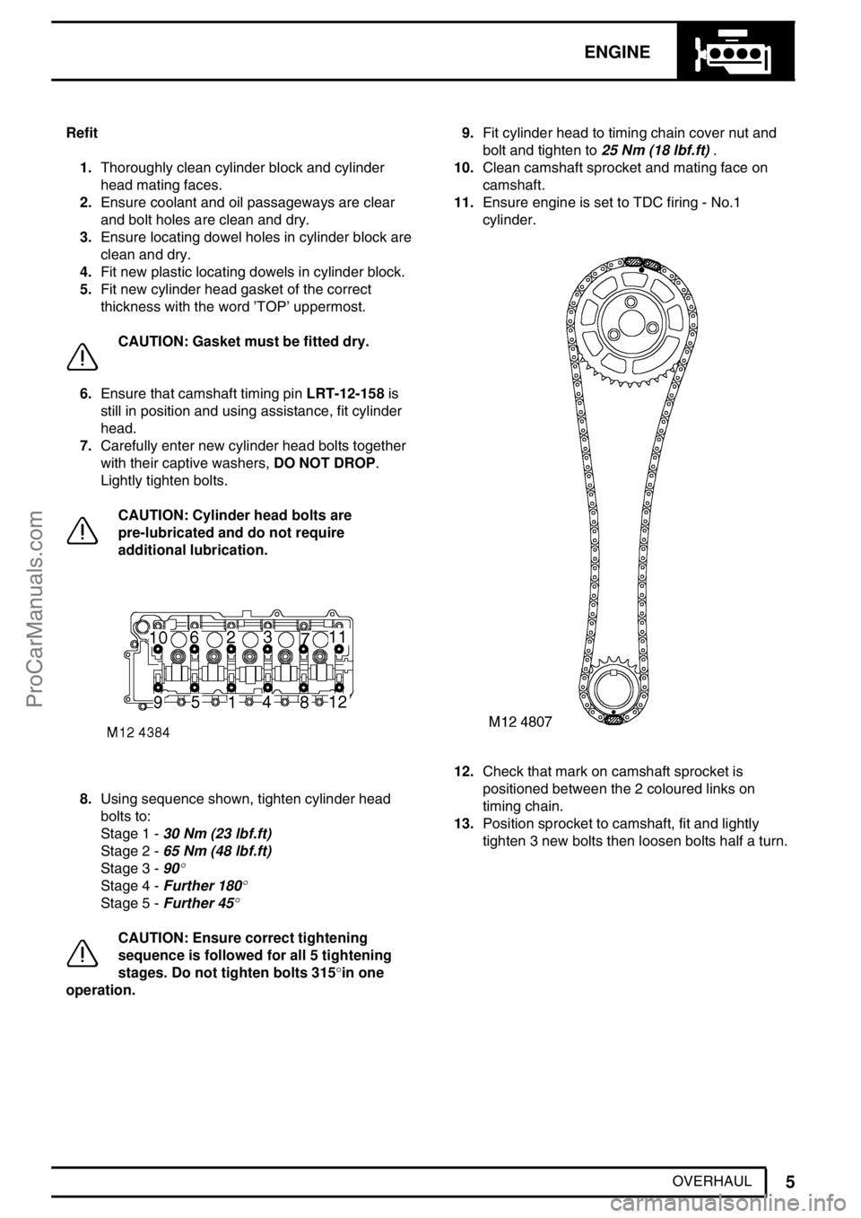
8.Using sequence shown, tighten cylinder head
bolts to:
Stage 1 -30 Nm (23 lbf.ft)
Stage 2 -65 Nm (48 lbf.ft)
Stage 3 -90
°
Stage 4 -Further 180°
Stage 5 -Further 45°
CAUTION: Ensure correct tightening
sequence is followed for all 5 tightening
stages. Do not tighten bolts 315°in one
operation.9.Fit cylinder head to timing chain cover nut and
bolt and tighten to25 Nm (18 lbf.ft).
10.Clean camshaft sprocket and mating face on
camshaft.
11.Ensure engine is set to TDC firing - No.1
cylinder.
12.Check that mark on camshaft sprocket is
positioned between the 2 coloured links on
timing chain.
13.Position sprocket to camshaft, fit and lightly
tighten 3 new bolts then loosen bolts half a turn.
ProCarManuals.com
Page 392 of 667

REAR AXLE AND FINAL DRIVE
5
REPAIR DIFFERENTIAL ASSEMBLY - 90
Service repair no - 51.15.01
Remove
1.Using suitable container, drain axle oil.
2.Mark differential and propeller shaft flanges to
facilitate reassembly.
3.Remove 4 bolts and disconnect propeller shaft
from differential. Tie aside.
4.Remove 5 hub drive member bolts and withdraw
axle half shafts sufficiently to disengage from
differential unit.
5.Remove 10 nuts securing differential to axle
case.
6.Withdraw differential unit.
NOTE: The differential unit can only be
serviced as a complete assembly with
matching drive pinion. For advice ring
Land Rover Service Department.Refit
7.Ensure mating faces are clean and apply a bead
of RTV sealant to axle case.
8.Support differential unit and position on axle
casing.
9.Secure with self locking nuts and tighten to40
Nm (30lbf/ft).
10.Align marks on flanges and secure propeller
shaft to differential. Tighten bolts to48 Nm (35
lbf/ft).
11.Refit half shafts, using new drive member
gaskets. Tighten bolts to65 Nm (48 lbf/ft).
12.Refill axle oil with approved lubricantSee
LUBRICANTS, FLUIDS AND CAPACITIES,
Information. Recommended lubricants and
fluids.
ProCarManuals.com