Page 154 of 667
ENGINE
29
REPAIR VALVE - RELIEF - OIL PRESSURE
Service repair no - 12.60.56
Remove
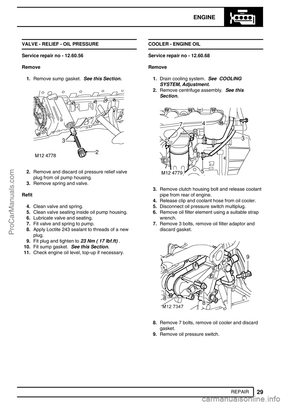
1.Remove sump gasket.See this Section.
2.Remove and discard oil pressure relief valve
plug from oil pump housing.
3.Remove spring and valve.
Refit
4.Clean valve and spring.
5.Clean valve seating inside oil pump housing.
6.Lubricate valve and seating.
7.Fit valve and spring to pump.
8.Apply Loctite 243 sealant to threads of a new
plug.
9.Fit plug and tighten to23 Nm ( 17 lbf.ft).
10.Fit sump gasket.See this Section.
11.Check engine oil level, top-up if necessary.COOLER - ENGINE OIL
Service repair no - 12.60.68
Remove
1.Drain cooling system.See COOLING
SYSTEM, Adjustment.
2.Remove centrifuge assembly.See this
Section.
3.Remove clutch housing bolt and release coolant
pipe from rear of engine.
4.Release clip and coolant hose from oil cooler.
5.Disconnect oil pressure switch multiplug.
6.Remove oil filter element using a suitable strap
wrench.
7.Remove 3 bolts, remove oil filter adaptor and
discard gasket.
8.Remove 7 bolts, remove oil cooler and discard
gasket.
9.Remove oil pressure switch.
ProCarManuals.com
Page 164 of 667
ENGINE
5
OVERHAUL Refit
1.Thoroughly clean cylinder block and cylinder
head mating faces.
2.Ensure coolant and oil passageways are clear
and bolt holes are clean and dry.
3.Ensure locating dowel holes in cylinder block are
clean and dry.
4.Fit new plastic locating dowels in cylinder block.
5.Fit new cylinder head gasket of the correct
thickness with the word’TOP’uppermost.
CAUTION: Gasket must be fitted dry.
6.Ensure that camshaft timing pinLRT-12-158is
still in position and using assistance, fit cylinder
head.
7.Carefully enter new cylinder head bolts together
with their captive washers,DO NOT DROP.
Lightly tighten bolts.
CAUTION: Cylinder head bolts are
pre-lubricated and do not require
additional lubrication.
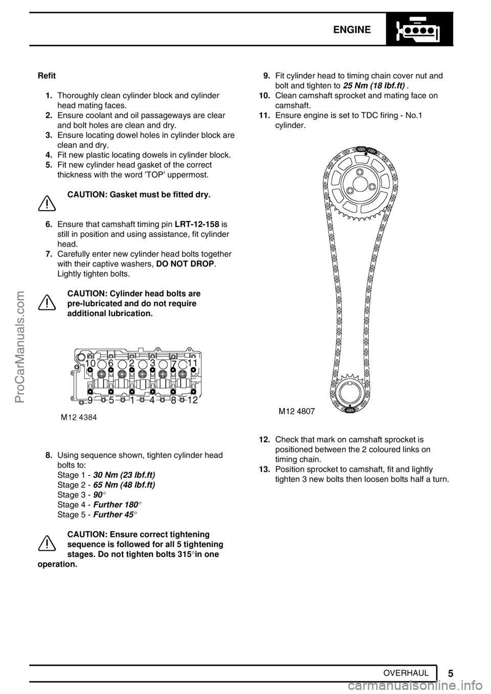
8.Using sequence shown, tighten cylinder head
bolts to:
Stage 1 -30 Nm (23 lbf.ft)
Stage 2 -65 Nm (48 lbf.ft)
Stage 3 -90
°
Stage 4 -Further 180°
Stage 5 -Further 45°
CAUTION: Ensure correct tightening
sequence is followed for all 5 tightening
stages. Do not tighten bolts 315°in one
operation.9.Fit cylinder head to timing chain cover nut and
bolt and tighten to25 Nm (18 lbf.ft).
10.Clean camshaft sprocket and mating face on
camshaft.
11.Ensure engine is set to TDC firing - No.1
cylinder.
12.Check that mark on camshaft sprocket is
positioned between the 2 coloured links on
timing chain.
13.Position sprocket to camshaft, fit and lightly
tighten 3 new bolts then loosen bolts half a turn.
ProCarManuals.com
Page 170 of 667
ENGINE
11
OVERHAUL
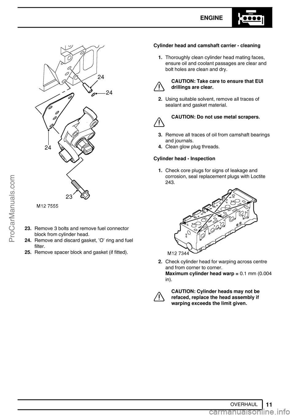
23.Remove 3 bolts and remove fuel connector
block from cylinder head.
24.Remove and discard gasket,’O’ring and fuel
filter.
25.Remove spacer block and gasket (if fitted).Cylinder head and camshaft carrier - cleaning
1.Thoroughly clean cylinder head mating faces,
ensure oil and coolant passages are clear and
bolt holes are clean and dry.
CAUTION: Take care to ensure that EUI
drillings are clear.
2.Using suitable solvent, remove all traces of
sealant and gasket material.
CAUTION: Do not use metal scrapers.
3.Remove all traces of oil from camshaft bearings
and journals.
4.Clean glow plug threads.
Cylinder head - Inspection
1.Check core plugs for signs of leakage and
corrosion, seal replacement plugs with Loctite
243.
2.Check cylinder head for warping across centre
and from corner to corner.
Maximum cylinder head warp =0.1 mm (0.004
in).
CAUTION: Cylinder heads may not be
refaced, replace the head assembly if
warping exceeds the limit given.
ProCarManuals.com
Page 171 of 667
12ENGINE
12
OVERHAUL Lash adjusters and finger followers - Inspection
1.Check lash adjuster bores for scoring and signs
of wear or damage.
2.Check lash adjusters for signs of wear, scoring
and overheating, replace as necessary. Ensure
oil hole in each lash adjuster is clear.
CAUTION: Store lash adjusters upright
and in their fitted order.
3.Check finger followers for wear and that rollers
are free to rotate.
CAUTION: Store finger followers in their
fitted order.
Camshaft - Inspection
1.Check camshaft lobes and bearing journals for
signs of scoring and wear.
2.Check bearing surfaces in cylinder head and
camshaft carrier for signs of scoring and wear.
CAUTION: Cylinder head and camshaft
carrier are machined together as an
assembly, if bearing surfaces in either
component are damaged, both components must
be replaced as an assembly.Camshaft - Check end-float
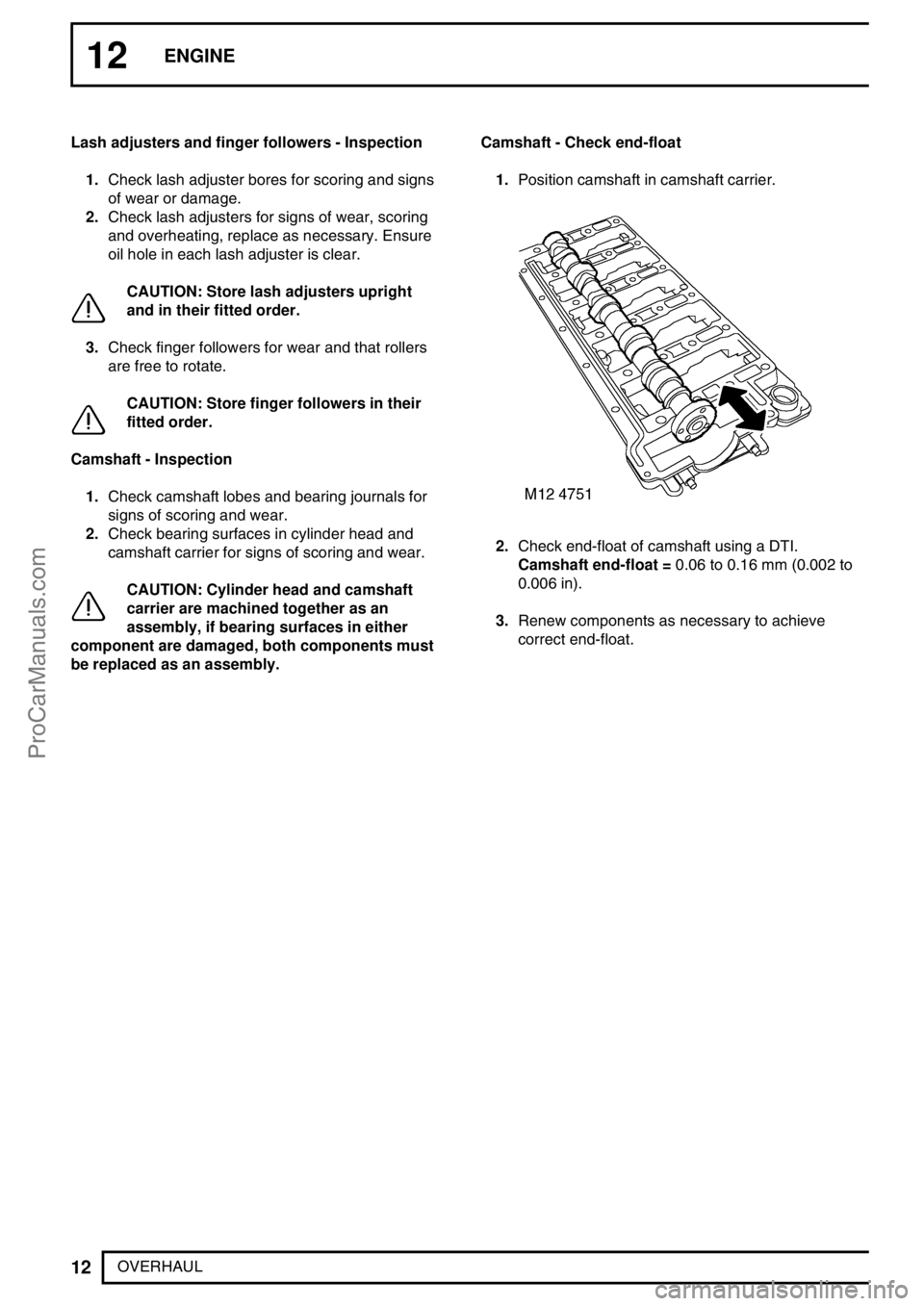
1.Position camshaft in camshaft carrier.
2.Check end-float of camshaft using a DTI.
Camshaft end-float =0.06 to 0.16 mm (0.002 to
0.006 in).
3.Renew components as necessary to achieve
correct end-float.
ProCarManuals.com
Page 172 of 667
ENGINE
13
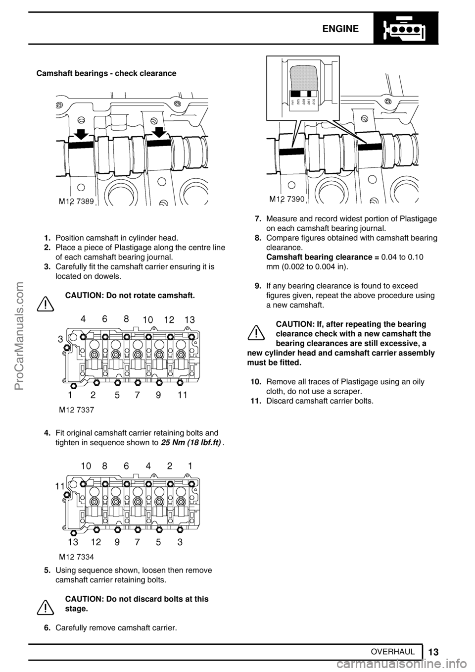
OVERHAUL Camshaft bearings - check clearance
1.Position camshaft in cylinder head.
2.Place a piece of Plastigage along the centre line
of each camshaft bearing journal.
3.Carefully fit the camshaft carrier ensuring it is
located on dowels.
CAUTION: Do not rotate camshaft.
4.Fit original camshaft carrier retaining bolts and
tighten in sequence shown to25 Nm (18 lbf.ft).
5.Using sequence shown, loosen then remove
camshaft carrier retaining bolts.
CAUTION: Do not discard bolts at this
stage.
6.Carefully remove camshaft carrier.
7.Measure and record widest portion of Plastigage
on each camshaft bearing journal.
8.Compare figures obtained with camshaft bearing
clearance.
Camshaft bearing clearance =0.04 to 0.10
mm (0.002 to 0.004 in).
9.If any bearing clearance is found to exceed
figures given, repeat the above procedure using
a new camshaft.
CAUTION: If, after repeating the bearing
clearance check with a new camshaft the
bearing clearances are still excessive, a
new cylinder head and camshaft carrier assembly
must be fitted.
10.Remove all traces of Plastigage using an oily
cloth, do not use a scraper.
11.Discard camshaft carrier bolts.
ProCarManuals.com
Page 175 of 667
12ENGINE
16
OVERHAUL 5.Repeat above procedures for remaining rocker
arms.
CAUTION: Keep rocker arms in their fitted
order.Rocker arms and shaft - Inspection
1.Clean rocker arms and shaft, ensure oilways are
clear.
CAUTION: Identify type of rocker shaft
fitted. Engine Serial No. Prefixes 10P to
14P - Type A rocker shaft. Engine Serial
No. Prefixes 15P to 19P - Type B rocker shaft.
Type B rocker arms and shaft may be fitted to
Engine Serial No. Prefixes 10P to 14P as an
assembly.
2.Check diameter of each rocker arm journal on
shaft, take 2 measurements at 180°in centre of
journal.
Journal diameter =26.971 to 26.998 mm
(1.062 to 1.063 in)
CAUTION: Any ovality must be within
limits given.
ProCarManuals.com
Page 176 of 667
ENGINE
17
OVERHAUL
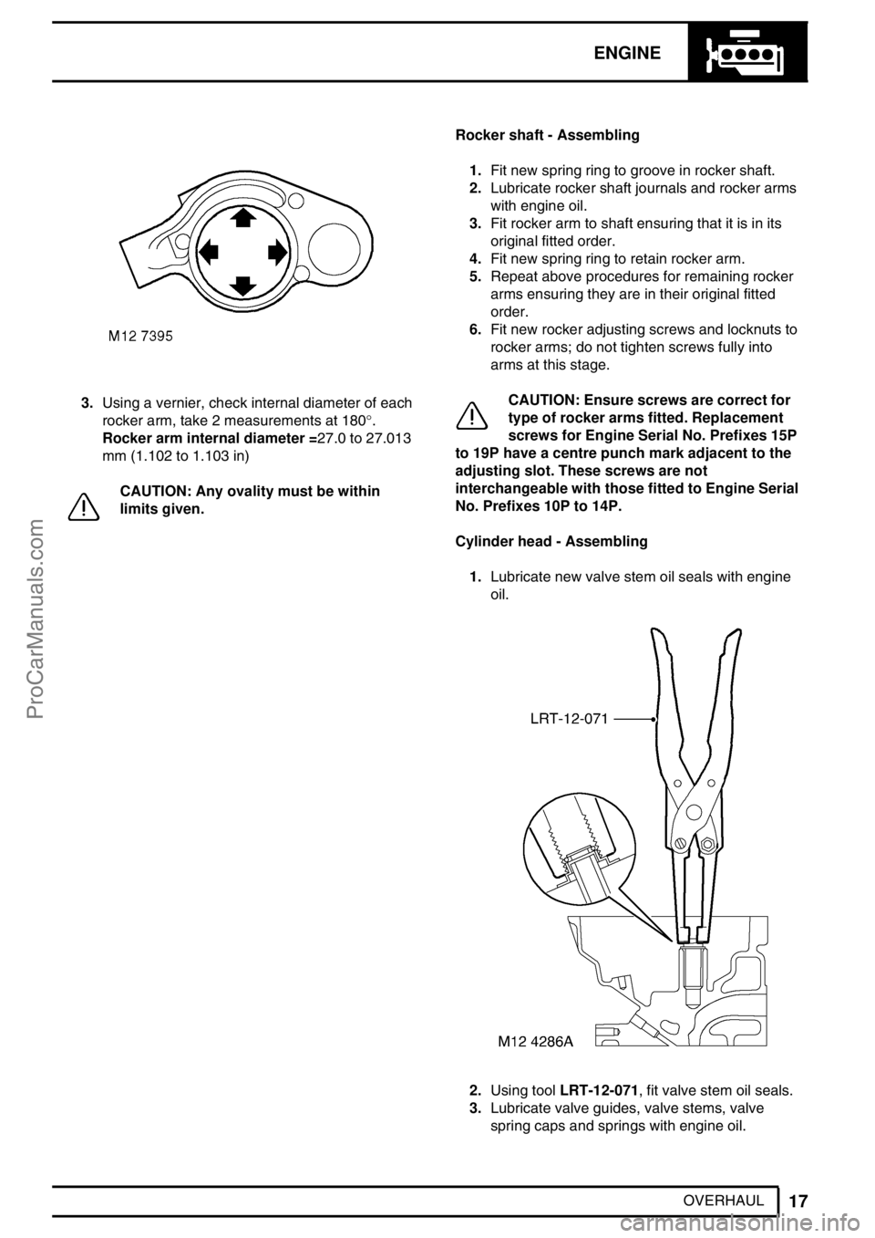
3.Using a vernier, check internal diameter of each
rocker arm, take 2 measurements at 180°.
Rocker arm internal diameter =27.0 to 27.013
mm (1.102 to 1.103 in)
CAUTION: Any ovality must be within
limits given.Rocker shaft - Assembling
1.Fit new spring ring to groove in rocker shaft.
2.Lubricate rocker shaft journals and rocker arms
with engine oil.
3.Fit rocker arm to shaft ensuring that it is in its
original fitted order.
4.Fit new spring ring to retain rocker arm.
5.Repeat above procedures for remaining rocker
arms ensuring they are in their original fitted
order.
6.Fit new rocker adjusting screws and locknuts to
rocker arms; do not tighten screws fully into
arms at this stage.
CAUTION: Ensure screws are correct for
type of rocker arms fitted. Replacement
screws for Engine Serial No. Prefixes 15P
to 19P have a centre punch mark adjacent to the
adjusting slot. These screws are not
interchangeable with those fitted to Engine Serial
No. Prefixes 10P to 14P.
Cylinder head - Assembling
1.Lubricate new valve stem oil seals with engine
oil.
2.Using toolLRT-12-071, fit valve stem oil seals.
3.Lubricate valve guides, valve stems, valve
spring caps and springs with engine oil.
ProCarManuals.com
Page 183 of 667
12ENGINE
24
OVERHAUL Inspection
CAUTION: Inspection/overhaul procedures
for the oil pump are limited to carrying out
dimensional checks. In the event of wear
or damage being found, a replacement pump and
stiffener plate assembly must be fitted.
Oil pump
1.Remove and discard 5 screws securing cover to
oil pump, remove cover.
2.Using a felt tipped pen, make suitable alignment
marks between inner and outer rotors and pump
body.
3.Remove inner and outer rotors.
4.Check rotors, cover and pump body for signs of
scoring and wear.
5.Fit rotors ensuring that reference marks are
aligned and identification mark on inner rotor is
facing outwards.
6.Using feeler gauges, check pump body to outer
rotor clearance:
Pump body to outer rotor clearance =0.295
to 0.375 mm (0.012 to 0.015 in)
7.Using feeler gauges, check clearance of inner to
outer rotor in 2 positions, both clearances must
be within limit given:
Inner to outer rotor clearance =0.13 mm (0.05
in)
ProCarManuals.com