Page 25 of 75
V6 Engine AJ-V6/AJ28
20to each VVT unit is supplied via fixed oilways in
the cylinder head and not through a separate
bush carrier. This arrangement requires a feed
through the camshaft side of the VVT unit from
the main cylinder head supply. The oil feed is
controlled by the VVT oil control valve, a solenoid
operated shuttle valve, which is bolted directly to
the cylinder head. From the oil control valve, the
flow is via the thrust bearing cap, through
drillings in the camshaft and then through the
hollow fixing bolt which secures the VVT unit.
Drain holes are provided at the rear (camside)
face of the VVT unit for any residual oil which has
seeped past the piston.
Operation
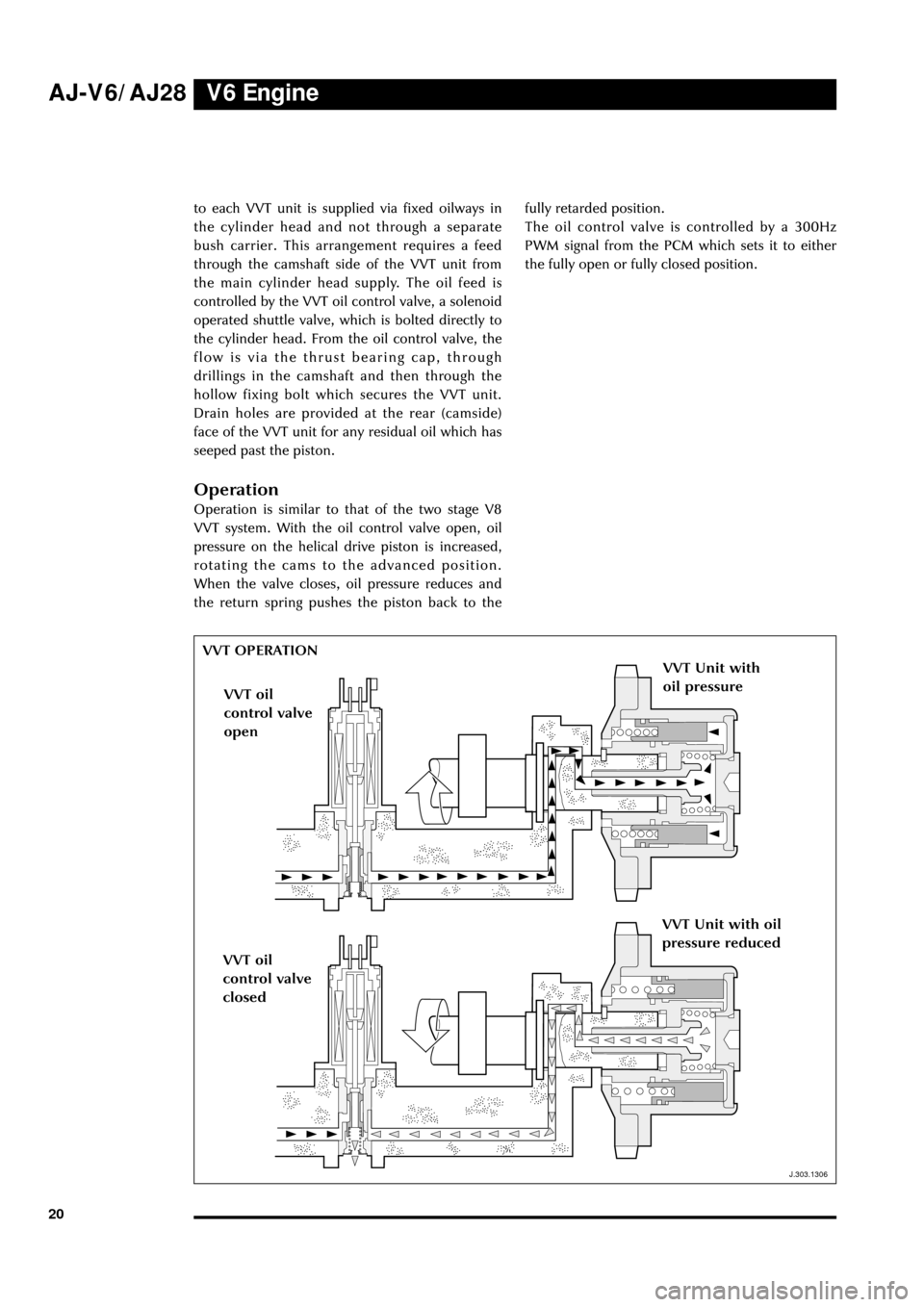
Operation is similar to that of the two stage V8
VVT system. With the oil control valve open, oil
pressure on the helical drive piston is increased,
rotating the cams to the advanced position.
When the valve closes, oil pressure reduces and
the return spring pushes the piston back to thefully retarded position.
The oil control valve is controlled by a 300Hz
PWM signal from the PCM which sets it to either
the fully open or fully closed position.
J.303.1306
VVT OPERATION
VVT Unit with
oil pressure
VVT oil
control valve
open
VVT oil
control valve
closed
VVT Unit with oil
pressure reduced
J.303.1306
Page 26 of 75
V6 EngineAJ-V6/AJ28
21
Air Induction System
range, the manifold geometry can be set to three
different configurations, each of which maximises
the tuning effect over different parts of the range.
This variable geometry is achieved by the use of
two gate valves, the intake manifold tuning (IMT)
valves, which are controlled by the engine
management system.Air Intake
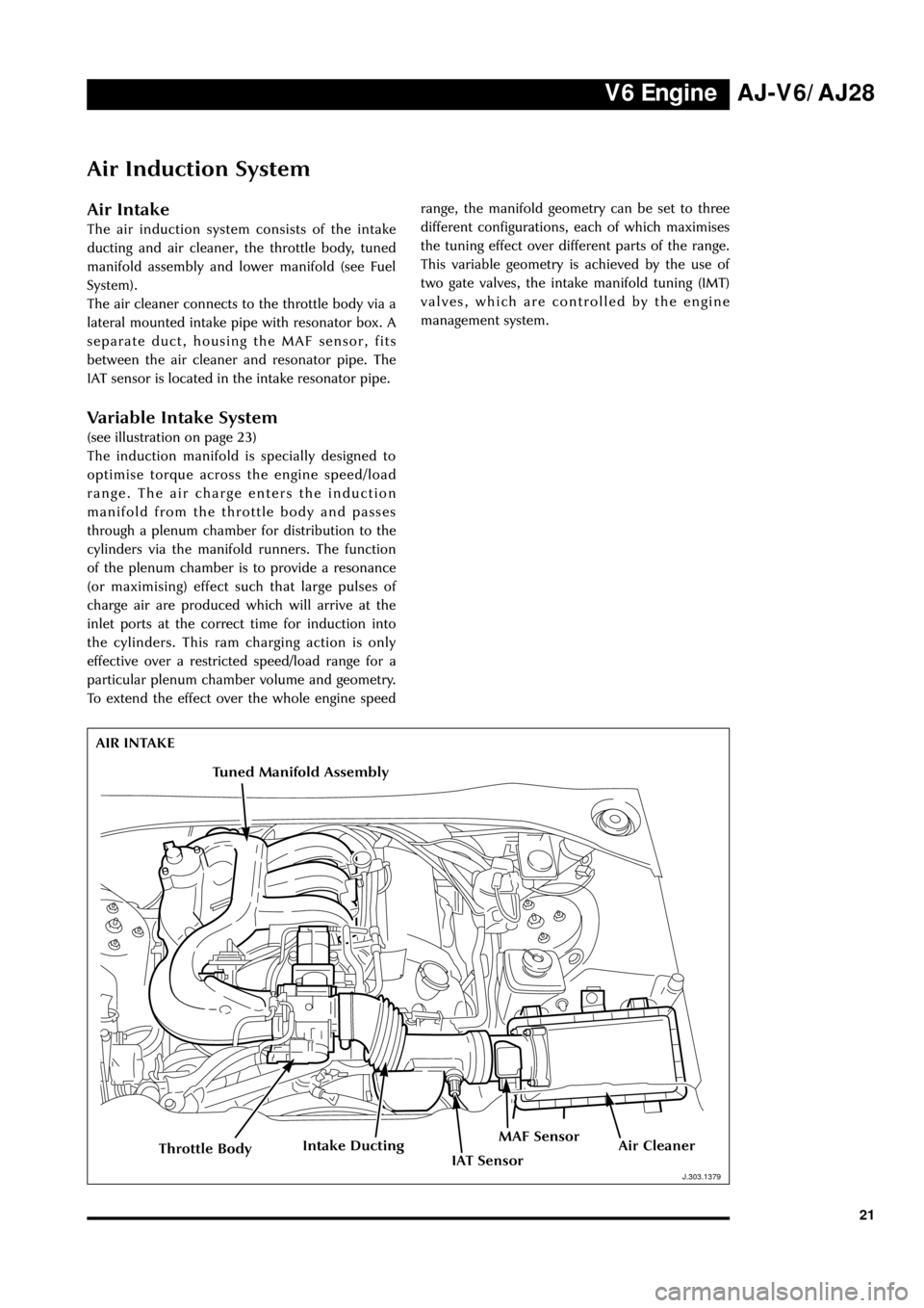
The air induction system consists of the intake
ducting and air cleaner, the throttle body, tuned
manifold assembly and lower manifold (see Fuel
System).
The air cleaner connects to the throttle body via a
lateral mounted intake pipe with resonator box. A
separate duct, housing the MAF sensor, fits
between the air cleaner and resonator pipe. The
IAT sensor is located in the intake resonator pipe.
Variable Intake System
(see illustration on page 23)
The induction manifold is specially designed to
optimise torque across the engine speed/load
range. The air charge enters the induction
manifold from the throttle body and passes
through a plenum chamber for distribution to the
cylinders via the manifold runners. The function
of the plenum chamber is to provide a resonance
(or maximising) effect such that large pulses of
charge air are produced which will arrive at the
inlet ports at the correct time for induction into
the cylinders. This ram charging action is only
effective over a restricted speed/load range for a
particular plenum chamber volume and geometry.
To extend the effect over the whole engine speed
J.303.1379
AIR INTAKE
J.303.1379
Air CleanerIntake DuctingMAF Sensor
IAT SensorThrottle Body
Tuned Manifold Assembly
Page 27 of 75
V6 Engine AJ-V6/AJ28
22
D.303.1217
INDUCTION MANIFOLD
D.303.1217
Top IMT valve
Bottom
IMT valve
Construction
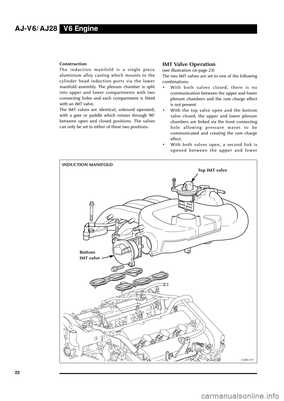
The induction manifold is a single piece
aluminium alloy casting which mounts to the
cylinder head induction ports via the lower
manifold assembly. The plenum chamber is split
into upper and lower compartments with two
connecting holes and each compartment is fitted
with an IMT valve.
The IMT valves are identical, solenoid operated,
with a gate or paddle which rotates through 90û
between open and closed positions. The valves
can only be set to either of these two positions.IMT Valve Operation
(see illustration on page 23)
The two IMT valves are set to one of the following
combinations:
¥ With both valves closed, there is no
communication between the upper and lower
plenum chambers and the ram charge effect
is not present
¥ With the top valve open and the bottom
valve closed, the upper and lower plenum
chambers are linked via the front connecting
hole allowing pressure waves to be
communicated and creating the ram charge
effect.
¥ With both valves open, a second link is
opened between the upper and lower
Page 28 of 75
V6 EngineAJ-V6/AJ28
23
J.303.1344
VARIABLE INTAKE SYSTEM
Both IMT valves Closed
Top IMT valve Open and the
Bottom IMT valve Closed
Both IMT valves open
J.303.1344
Page 29 of 75
V6 Engine AJ-V6/AJ28
24
J.303.1358
TORQUE CHARACTERISTICS
Top inlet manifold tuning valve
Advanced
Closed
325
D.303.1358
Side inlet manifold tuning valve
Open
Closed
Closed
ClosedOpen
Retarded
V. V. T.
175
200
225
250
275
300
125
150
2000700060005000400030001000
Engine Speed (rpm)
Brake Torque (Nm)
chambers via the rear connecting hole,
further increasing the ram effect.via the rear
connecting hole.
System Performance
The valve open/close combinations across the
engine speed range have been selected in
conjunction with the VVT system to provide an
optimised torque curve. Referring to the graph, it
can be seen that there are five states that the IMT
valves and VVT can adopt throughout the engine
speed range.
Page 30 of 75

V6 EngineAJ-V6/AJ28
25
Throttle Control System
D.303.1219
Introduction
A fully electronically controlled throttle is fitted,
requiring no mechanical connection between the
accelerator pedal and throttle body. The driver
operates a normal foot pedal and a transducer on
the pedal shaft converts the mechanical rotation
to electrical signals which are sent to the
powertrain control module (PCM) to indicate
driver demand. Signals requesting the desired
throttle plate angle are sent from the PCM to an
electronic module on the throttle assembly, the
throttle actuator control (TAC) module, which
provides closed loop control of the motorised
throttle plate. The actual angle of the throttle
plate is indicated to the PCM by the throttle
position (TP) sensor.
The throttle assembly is mechanically simpler
than those used on previous Jaguar vehicles,
consisting essentially of a motor driven throttle
plate with no other actuators or vacuum devices
(eg cruise control).
Operation is designed to be transparent to the
driver with a total delay of less than 70ms
between pedal actuation and throttle movement.
THROTTLE BODY
Control Components
Throttle Assembly
The electronic throttle assembly consists of four
component sub-assemblies:
¥ throttle body
¥ drive motor unit
¥ throttle actuator control (TAC) module
¥ throttle position (TP) sensor
The throttle body is an aluminium casting with a
70mm air intake bore, housing a shaft with brass
throttle plate, rotating in ball bearings, and with a
spur gear and return spring fitted to the drive
end. A stop screw against the spur gear is pre-
adjusted and sealed on assembly to set the
throttle mechanical closed position and a second
stop prevents the throttle plate from being driven
beyond the full throttle position. The internal
tooth spur gear is driven directly from the motor
shaft which is offset to the throttle shaft. The
motor drive unit is an integral assembly
containing the motor, an inductive position
encoder and the mating connector to the TAC
module. Should the motor fail, the return spring
will move the throttle plate to the closed position.
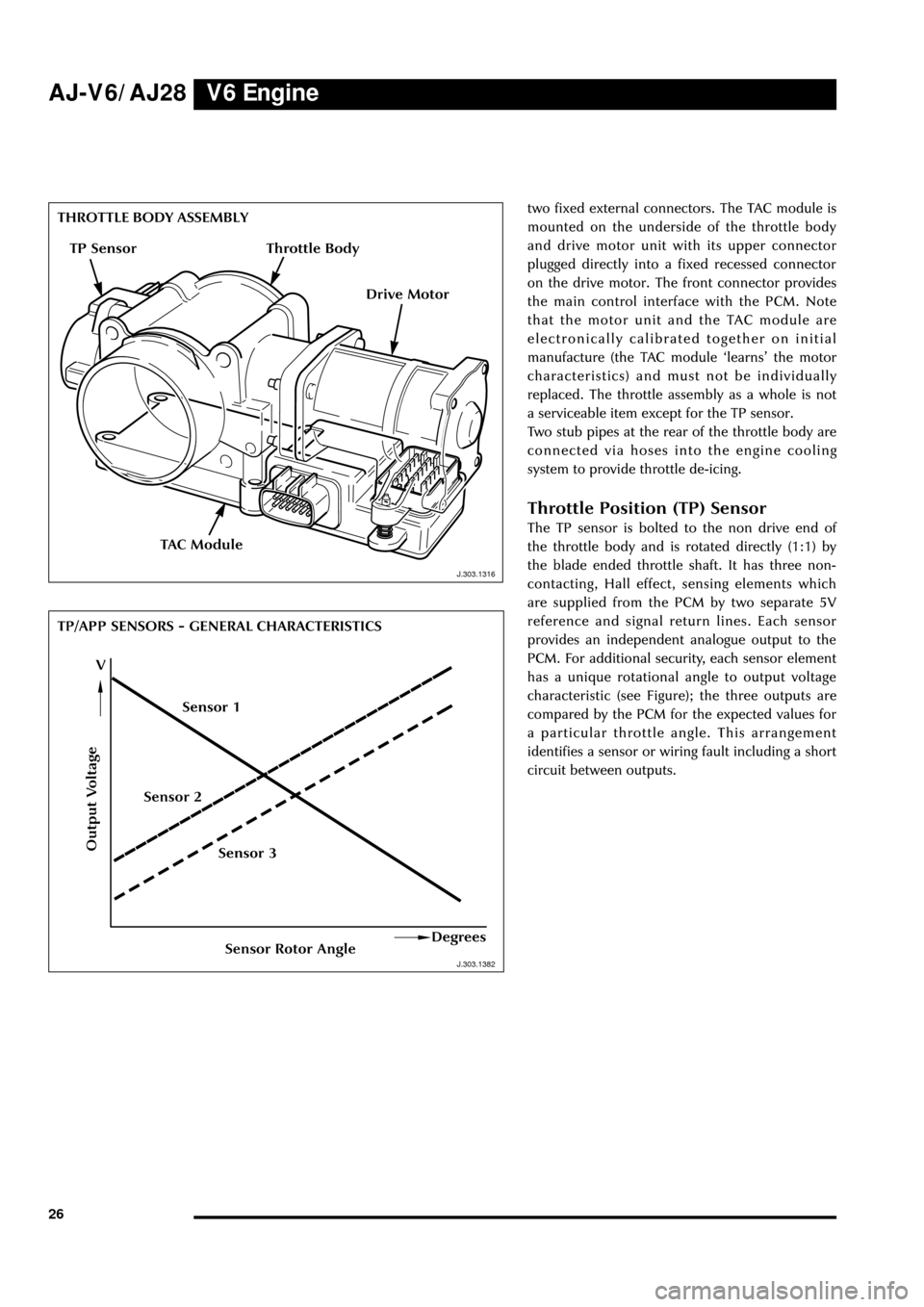
The TAC module consists of a printed circuit
board enclosed within an aluminium module with
D.303.1219
Page 31 of 75
V6 Engine AJ-V6/AJ28
26
J.303.1316
J.303.1362
THROTTLE BODY ASSEMBLY
TP/APP SENSORS - GENERAL CHARACTERISTICStwo fixed external connectors. The TAC module is
mounted on the underside of the throttle body
and drive motor unit with its upper connector
plugged directly into a fixed recessed connector
on the drive motor. The front connector provides
the main control interface with the PCM. Note
that the motor unit and the TAC module are
electronically calibrated together on initial
manufacture (the TAC module ÔlearnsÕ the motor
characteristics) and must not be individually
replaced. The throttle assembly as a whole is not
a serviceable item except for the TP sensor.
Two stub pipes at the rear of the throttle body are
connected via hoses into the engine cooling
system to provide throttle de-icing.
Throttle Position (TP) Sensor
The TP sensor is bolted to the non drive end of
the throttle body and is rotated directly (1:1) by
the blade ended throttle shaft. It has three non-
contacting, Hall effect, sensing elements which
are supplied from the PCM by two separate 5V
reference and signal return lines. Each sensor
provides an independent analogue output to the
PCM. For additional security, each sensor element
has a unique rotational angle to output voltage
characteristic (see Figure); the three outputs are
compared by the PCM for the expected values for
a particular throttle angle. This arrangement
identifies a sensor or wiring fault including a short
circuit between outputs.
Output Voltage
Sensor Rotor AngleDegrees
V
TAC Module
J.303.1382 J.303.1316
TP Sensor
Drive Motor
Sensor 3 Sensor 2Sensor 1
Throttle Body
Page 32 of 75
V6 EngineAJ-V6/AJ28
27
D.418.428
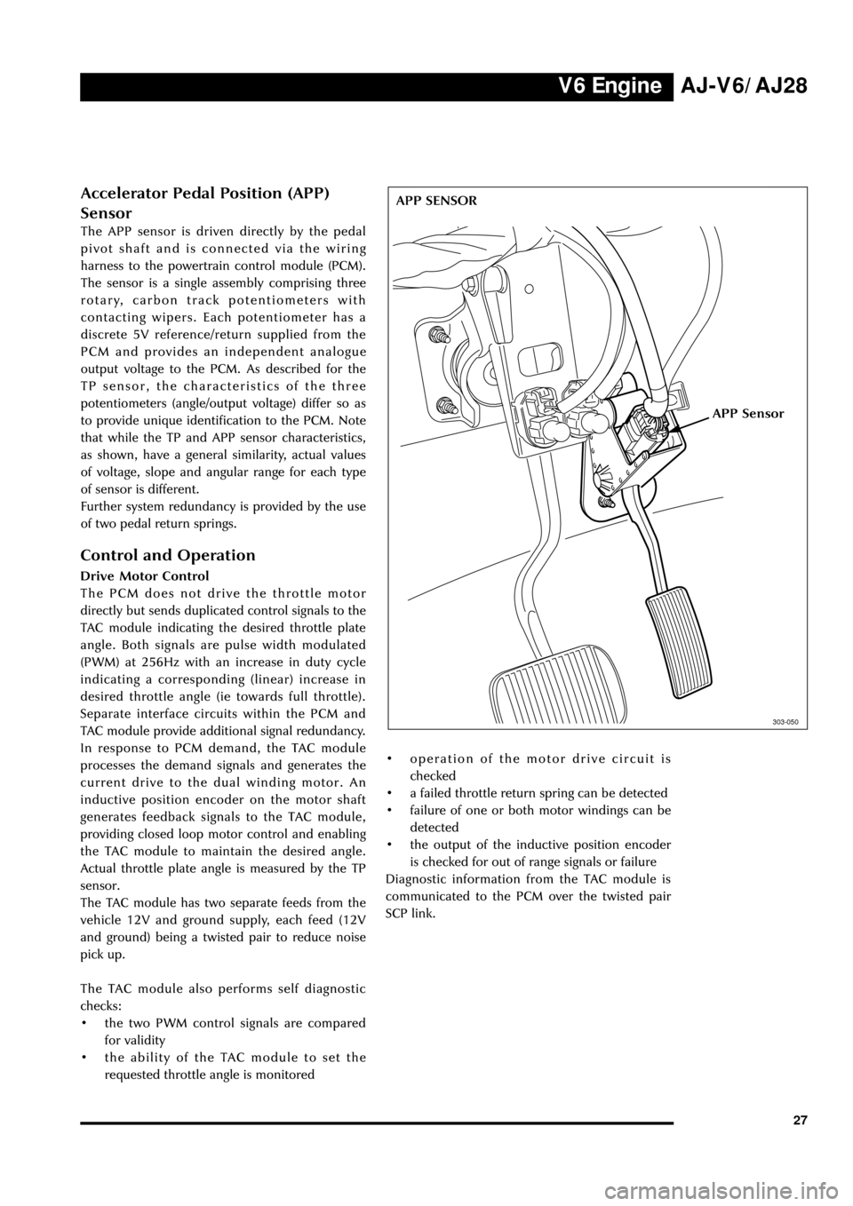
APP Sensor
303-050
APP SENSORAccelerator Pedal Position (APP)
Sensor
The APP sensor is driven directly by the pedal
pivot shaft and is connected via the wiring
harness to the powertrain control module (PCM).
The sensor is a single assembly comprising three
rotary, carbon track potentiometers with
contacting wipers. Each potentiometer has a
discrete 5V reference/return supplied from the
PCM and provides an independent analogue
output voltage to the PCM. As described for the
TP sensor, the characteristics of the three
potentiometers (angle/output voltage) differ so as
to provide unique identification to the PCM. Note
that while the TP and APP sensor characteristics,
as shown, have a general similarity, actual values
of voltage, slope and angular range for each type
of sensor is different.
Further system redundancy is provided by the use
of two pedal return springs.
Control and Operation
Drive Motor Control
The PCM does not drive the throttle motor
directly but sends duplicated control signals to the
TAC module indicating the desired throttle plate
angle. Both signals are pulse width modulated
(PWM) at 256Hz with an increase in duty cycle
indicating a corresponding (linear) increase in
desired throttle angle (ie towards full throttle).
Separate interface circuits within the PCM and
TAC module provide additional signal redundancy.
In response to PCM demand, the TAC module
processes the demand signals and generates the
current drive to the dual winding motor. An
inductive position encoder on the motor shaft
generates feedback signals to the TAC module,
providing closed loop motor control and enabling
the TAC module to maintain the desired angle.
Actual throttle plate angle is measured by the TP
sensor.
The TAC module has two separate feeds from the
vehicle 12V and ground supply, each feed (12V
and ground) being a twisted pair to reduce noise
pick up.
The TAC module also performs self diagnostic
checks:
¥ the two PWM control signals are compared
for validity
¥ the ability of the TAC module to set the
requested throttle angle is monitored¥ operation of the motor drive circuit is
checked
¥ a failed throttle return spring can be detected
¥ failure of one or both motor windings can be
detected
¥ the output of the inductive position encoder
is checked for out of range signals or failure
Diagnostic information from the TAC module is
communicated to the PCM over the twisted pair
SCP link.