Page 25 of 75

V6 Engine AJ-V6/AJ28
20to each VVT unit is supplied via fixed oilways in
the cylinder head and not through a separate
bush carrier. This arrangement requires a feed
through the camshaft side of the VVT unit from
the main cylinder head supply. The oil feed is
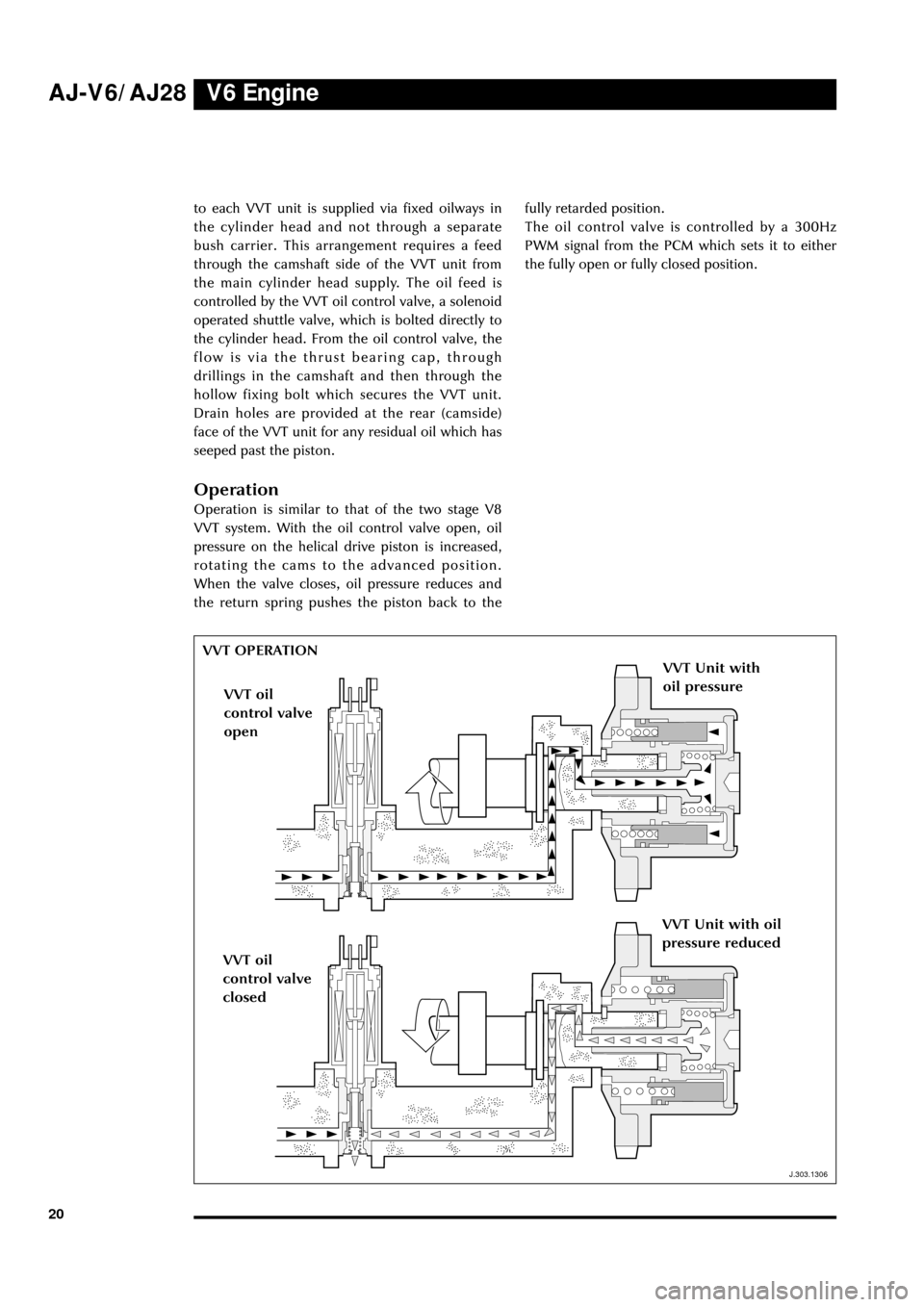
controlled by the VVT oil control valve, a solenoid
operated shuttle valve, which is bolted directly to
the cylinder head. From the oil control valve, the
flow is via the thrust bearing cap, through
drillings in the camshaft and then through the
hollow fixing bolt which secures the VVT unit.
Drain holes are provided at the rear (camside)
face of the VVT unit for any residual oil which has
seeped past the piston.
Operation
Operation is similar to that of the two stage V8
VVT system. With the oil control valve open, oil
pressure on the helical drive piston is increased,
rotating the cams to the advanced position.
When the valve closes, oil pressure reduces and
the return spring pushes the piston back to thefully retarded position.
The oil control valve is controlled by a 300Hz
PWM signal from the PCM which sets it to either
the fully open or fully closed position.
J.303.1306
VVT OPERATION
VVT Unit with
oil pressure
VVT oil
control valve
open
VVT oil
control valve
closed
VVT Unit with oil
pressure reduced
J.303.1306
Page 31 of 75

V6 Engine AJ-V6/AJ28
26
J.303.1316
J.303.1362
THROTTLE BODY ASSEMBLY
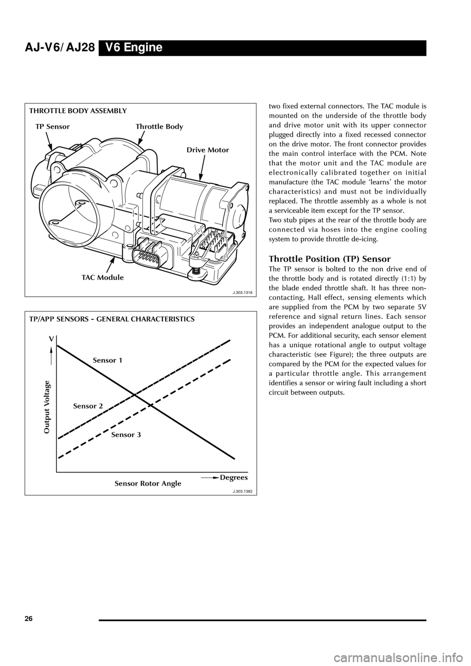
TP/APP SENSORS - GENERAL CHARACTERISTICStwo fixed external connectors. The TAC module is
mounted on the underside of the throttle body
and drive motor unit with its upper connector
plugged directly into a fixed recessed connector
on the drive motor. The front connector provides
the main control interface with the PCM. Note
that the motor unit and the TAC module are
electronically calibrated together on initial
manufacture (the TAC module ÔlearnsÕ the motor
characteristics) and must not be individually
replaced. The throttle assembly as a whole is not
a serviceable item except for the TP sensor.
Two stub pipes at the rear of the throttle body are
connected via hoses into the engine cooling
system to provide throttle de-icing.
Throttle Position (TP) Sensor
The TP sensor is bolted to the non drive end of
the throttle body and is rotated directly (1:1) by
the blade ended throttle shaft. It has three non-
contacting, Hall effect, sensing elements which
are supplied from the PCM by two separate 5V
reference and signal return lines. Each sensor
provides an independent analogue output to the
PCM. For additional security, each sensor element
has a unique rotational angle to output voltage
characteristic (see Figure); the three outputs are
compared by the PCM for the expected values for
a particular throttle angle. This arrangement
identifies a sensor or wiring fault including a short
circuit between outputs.
Output Voltage
Sensor Rotor AngleDegrees
V
TAC Module
J.303.1382 J.303.1316
TP Sensor
Drive Motor
Sensor 3 Sensor 2Sensor 1
Throttle Body
Page 44 of 75
V6 EngineAJ-V6/AJ28
39
D.303.1351D.303.1352
PAS PUMPA/C COMPRESSOR
D.303.1352
D.303.1369
Idler Pulleys
Two idler pulleys are used, one fixed by a single
bolt to the front cover and a second (see
illustration) fixed via a mounting bracket to the
upper RH side of the cylinder head and front
cover.
PAS Pump
The PAS pump is fixed by a single bolt to the LH
cylinder head and by two bolts to the front cover.
The pulley is constructed of lightweight phenolic
material.
Air Conditioning Compressor
The A/C compressor is mounted on the lower LH
side of the engine and is secured by two bolts to a
bracket fixed to the bedplate and by two lower
bolts directly to the oil sump.IDLER PULLEY
D.303.1351
D.303.1369