Page 1226 of 1395
Integrated Control Unit
UNOER,HOOD FUSE/BELAY 8OX
N0.41 (100A) N0.42 (40A)
Circuit Diagram -'98 - 00 Models
EATTERY
@*"WHT/BLK -....+ WHT
WHT/RED
IJNDER DASH FUSEi BELAY BOX
WINDSH ELD W PER/gsHERlIrTcH .
OFF/ NT INT
f7 f7
tltl
tl
tlBLU/BLK YEUBLU
GRN/BLK
lo/.Fn WINDSHIELD( il) WASHEF
Y
SWITCH
WHT/BLK
REASWINDOWWIPERMOTOR
f7
ILT GRN
t,,
-9
INTEGFATED coNTsoL UNIT I 85 I 83
23-66
8LK
G401G402
WHT/BLKWINDSHIELDWASHEFMOTOR
INTERIT,IITTENT WIPER RELAY CIRCUITNEAF WINDOW INTERMITTENTWIPER RELAY CIRCUIT
www.emanualpro.com
Page 1270 of 1395
Rear Window Defogger
Gomponent Location Index
FUSE/RELAY BOX
REAB WINDOW DEFOGGER SWTTCHInput Test, p89e 23-113
REAR WINDOW DEFOGGERFunction Test. page 23-112DetoggerWre Repair, page 23-112
rr^ja} aia al Irl
!
23-110
www.emanualpro.com
Page 1271 of 1395
EI
IGNITIONSWTCH
-f "r?h\_--,' I
I
I
I
WHT/8LK +WHT
a-Circuit Diagram
BATTERY
@-*"
l-
IJ
l"8LK
G401G402
N0.41 {100A) N0.42 (404)
UNDER-HOOD FUSE/REI-AY BOX
REAs WINDOW DEFOGGER SWITCHB1 {in ihe heater control panel)
b}l!;r.r
23-111
www.emanualpro.com
Page 1272 of 1395

Rear Window Defogger
Function Test
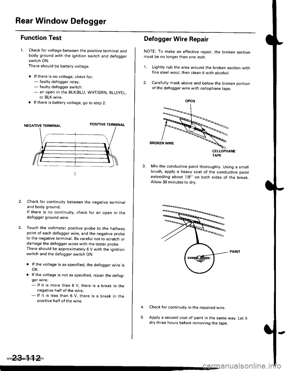
1. Check for voltage between the positive terminal andbody ground with the ignition switch and defoggerswitch ON.
There should be battery voltage.
. lf there is no voltage. check for:- faulty defogger relay.- faulty defogger switch.- an open ,n the BLK/BLU, WHT/GRN, BLU/YEL,
or BLK wire.
. lf there is battery voltage, go to step 2.
POSITIVE TERMINAL
Check for continuity between the negative terminaland body ground.
lf there is no continuity, check for an open in thedefogger ground wire.
Touch the voltmeter positive probe to the halfwaypoint of each defogger wire, and the negative probe
to the negative terminal. Be careful not to scratch ordamage the defogger wires with the tester probe.There should be approximately 6 V with the ignitionswitch and the defogger switch ON.
. lf the voltage is as specified, the defogger wire isoK.
. lf the voltage is not as specified, repair the defog-ger wire.- lf it is more than 6 V, there is a break in thenegative half of the wire.- lf it is less than 6 V, there is a break in thepositive half of the wire.
23-112
Defogger Wire Repair
NOTE: To make an effective repair, the broken sectionmust be no longer than one inch.
1. Lightly rub the area around the broken section withfine steel wool, then clean it with alcohol.
2. Carefully mask above and below the broken portionof the defogger wire with cellophane tape.
CELLOPHANETAPE
Mix the conductive paint thoroughly. Using a smallbrush, apply a heavy coat of the conductive paint
extending about 1/8" on both sides of the break.Allow 30 minutes to dry.
Check for continuity in the repaired wire.
Apply a second coat of paint in the same way. Let itdry three hours before removing the tape.
5,
OPEN
www.emanualpro.com
Page 1274 of 1395
Wipers/Washers
Component Location Index
SRS components are located in this area. Review the SRs component locations, precautions, and procedures in the s6ssection (24) before performing repairs or service.
REAB WINDOW WIPER MOTOBT€st, page 23-120WPSR/WASHER SWITCHTest. page 23- l't9
REAR WINDOW WIPERCONTROL UNlT 137 mod.llInput test. page 23-118
WINDSHIELD WIPER MOTORTost, page 23-119
UNDER.DASH FUSE/RELA
INTERMITTENT W|PEN RELAYCIBCUIT, REAR WINDOW INTERMTNENTwlPER RELAY CIBCUIT l'98 - 0O mod.t.lBOX (ln the integrated control unit)Input test, page 23-68
23-114
-
n
tff
www.emanualpro.com
Page 1276 of 1395
Wipers/Washers
Circuit Diagram (Rear Window) -'97 Model
UNDER.HOOD FUSE/RELAY BOX
@**'
N0.41 (100A) N0.42 (40A)WHT/BLK +WHT
I
G611G631
t'8LK
I
G202
,7!is--- ---- ----
JiJ frT
BLK
d-l
G401G4A2
23-116
www.emanualpro.com
Page 1277 of 1395
Circuit Diagram (Rear Windowl -'98 - 00 Models
BATTERYUNDER.HOOD FUSEi RELAY 80X
N0.41 (100A) N0.42 (40A)
@*,'WHT/BLK +WHTGNIT ONSW TCH
REAR WINDOWWPER MOTOR
Ot-
GRN/BLK
I
A n',$s".,,,
vil8t8E
IBLK
I
n-
G202
BLK
n_-:
G611G631
UNDEF-DASHFTJSE/RELAYBOX
JDLI OFF
INTEGRATED CONTROL UN T/Has bo ll-in re wndow\
t nlermillenl w per relay ]
BLK
.L-
G40lG402
I
-
23-117
www.emanualpro.com
Page 1278 of 1395

Wipers/Washers
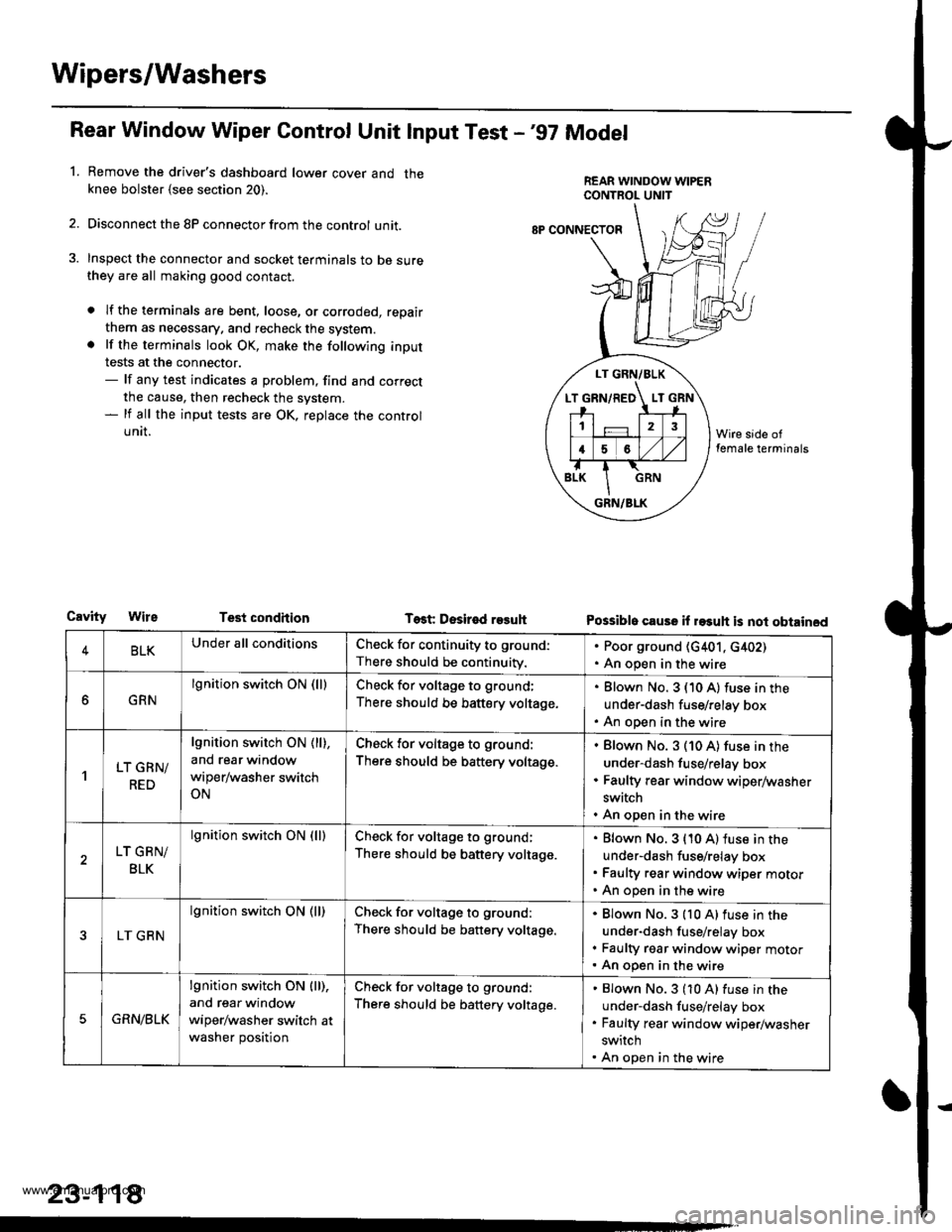
Rear Window Wiper Gontrol Unit lnput Test -'97 Model
Remove the driver's dashboard lower cover and theknee bolster {see section 20).
Disconnect the 8P connector from the control unit.
Inspect the connector and socket terminals to be surethey are all making good contact.
a lf the terminals are bent, loose, or corroded, repair
them as necessary. and recheck the system.. lf the terminals look OK, make the following input
tests at the connector.- lf any test indicates a problem, find and correct
the cause, then recheck the system.- lf all the input tests are OK, replace the control
UNII.
1.
LT GRN/BLK
T GRN/RED LT
12
16
GRN/BLK
8P CONNECTOF
CavityTest condhion Test Desir€d r93uhPossible cause il rasuh is not obtained
4BLKUnder all conditionsCheck for continuity to ground:
There should be continuity.
. Poor ground (G401, c402). An open in the wire
GRN
lgnition switch ON (lllCheck for voltage to ground;
There should be battery voltage.
Blown No. 3 (10 A) fuse in the
under-dash fuse/relay box
An open in the wire
'lLT GRN/
RED
lgnition switch ON ( ll),
and rear window
wiper/washer switch
ON
Check for voltage to ground:
There should be battery voltage.
Blown No. 3 (10 A) fuse in the
under-dash fuse/relay box
Faulty rear window wiper/washer
switch
An open in the wire
LT GRN/
BLK
lgnition switch ON (lllCheck for voltage to ground;
There should be battery voltage.
Blown No. 3 {10 A) fuse in the
under-dash fuse/relay box
Faulty rear window wiper motor
An open in the wire
LT GRN
lgnition switch ON (ll)Check for voltage to ground:
There should be battery voltage.
Blown No.3 {10 A)fuse in the
under-dash fuse/relay box
Faulty rgar window wiper motorAn open in the wire
5GRN/BLK
lgnition switch ON lll),
and rear window
wiper/washer switch at
washer position
Check for voltage to ground:
There should be battery voltage.
Blown No.3 (10 A) fuse in the
under-dash fuse/relay box
Faulty rear window wiper/washer
switch
An open in the wire
23-118
www.emanualpro.com