Page 3 of 1395
General lnformation
Chassis and Paint Codes ....................... 1-2
ldentification Number Locations ......... 1-10
Warning/Caution Label Locations ....... 1-11
Under-hood Emissions Control
Label .......... ..................... 1-15
Lift and Support Points
Lift and Safety Stands ....................... 1-19
Floor Jack ....................... 1-20
Towing .........1-21
Service Precautions
Pafts Marking Locations ..,................. 1-22
Precautions for Real-time 4WD
(Four-wheel Drivel ......... ................. 1 -23
www.emanualpro.com
Page 22 of 1395
Lift and Support Points
1.
Floor Jack
Block the rear wheels when raising the front of thevehicle; block the front wheels when raising the rearof the vehicle.
Place the blocks behind and ahead of the wheels,
Raise the vehicle high enough to insert the safetystanos.
Adjust and place the safety stands so the vehiclewill be approximately level, then lower the vehicleonto them.
Front:
Center the jack
bracket in the middleof the jack lift platform.
Always usg safety standg when working on or underany vehicle that is supported by only a iack.Nevor attempt to use a bumper jack for tifting orsupporting ths vehicl€.
Rsar:
JACK LIFT PLATFORM
Center the iackbracket in the middleof the iack lift platform.
1-20
JACK LIFT PLATFORM
www.emanualpro.com
Page 30 of 1395

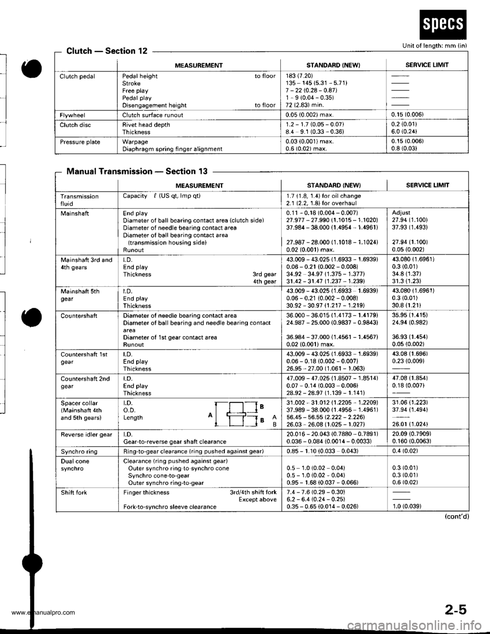
Unit of length: mm lin)ClutchSection 12
Manual TransmissionSection 13
MEASUREMENTSTANDARD INEWISERVICE LIMIT
Clutch pedalPedal height to floorStrokeFree playPedal play
Disengagement height to floor
183 (7.20)
135- 14515.31 - 5.71)7 - 2210.24 - 0.41J1-9 (0.04-0.35)
7212.83) min.
Clutch surface runout0.05 (0.002) max.0.r5 (0.006)
Clutch discRivet head depthThickness1.2 - 1.710.05- 0.07)8.4 9.1 (0.33,0.36)0.2 (0.01)
6.0 i0.24)
Pressure plateWarpageDiaphragm spring finger alignment0.03 (0.001)max.
0.6 (0.02) max.0.15 (0.006)
0.8 (0.03)
MEASUREM€NTSTANDARD INEW} I SERVICE I-IMIT
TransmissionfluidCapacity f (US qt, lmp qti1.7 11.8, 1.4)for oilchange2.1 (2.2, 1.8){or overhaul
MainshaftEnd play
Diameter of ball bearing contact area (clutch side)Diameter of needle bearing contact areaDiameter of ball bearing contact area(transmission housing side)Runout
0.'11 - 0.18 (0.004 - 0.007)27.977 - 27.990 (1.1015 - 1.1020)37.984 - 38.000 (1.4954- 1.4961)
27.987 - 28.000 (1.1018 - 1.1024)0.02 (0.0011max.
Adjust27.94 (1.100)
37.93 (1.493)
27.94 (1.100)
0.05 {0.002)
Mainshatt 3rd and4th gearsLD.End play
Thickness 3rd gear4th gear
43.009 - 43.025 1 1.6933 - 1.6939)0.06 - 0.21 (0.002 - 0.008)34.92 34.97 11.375 - 1.377)31.42 - 31.4'7 11.237 , 1.2391
43.08011.6961)0.3 (0.01)
34.811.37)31.311.23)
Mainshaft sthgearLD.End play
Thickness
43.009 - 43.02511.6933 1.6939)0.06 - 0.21 (0.002 - 0.008)30.92 - 30.97 {1.217 - 1.219)
43.08011.6961)0.3 (0.01)
30.8 (1.21)
CountershaftDiameter ol needle bearing contact areaDiameter oI ball bearing and needle bearing contact
Diameter o{ 1st gear contact areaRunout
36.000 - 36.015 {1.4173 - 1.4179)24.987 - 25.000 (0.9837 - 0.9843)
36.984 - 37.00011.4561 -1.4567)
0.02 (0.001)max.
3s.95 (1.415)
24.94 (0.982)
36.93 (1.4s4)
0.0s (0.002)
countershatt 1stgearLD.End playThickness
43.009 - 43.025 (1.6933 1.6939)0.06 - 0.18 (0.002 - 0.007i26.9s,27.00 (1.061 - 1.063)
43.08 (1.696)
0.2310.009)
Countershaft 2ndgeart.D.End playThickness
47.009 - 47.025 (1.8507 - 1.8514)0.07 - 0.14 10.003 ,0.006)
2As2 - 2a.97 l�1.139-1.1411
47.08 {1.854)0.18 (0.007)
Spacer collar(Mainshaft 4thand 5th gears)
t.D.o.D.Length A'ls I
le31 .002 - 31 .O12 11 .2205 , 1 .2205)37.989 - 38.000 (1.4956 1.4961)56.45 - 56.55 Q.222 - 2.226126.03,26.08 (1.025 - 1.027)
31.06 (1.223)
37.94 (1.494)
26.01 t1 .0241
Reverse idler geart.D.Gear-to-reverse gear shaft clearance20.01 6 - 20.043 (0.7880, 0.7891)0.036 - 0.084 (0.0014 - 0.0033)20.09 (0.7909)
0.16010.0063)
Synchro ringRing-to-gear clearance (ring pushed againsl gear)0.85 - r.10 (0.033 0.043)0.4 (0.02)
Dual coneClearance (ring pushed against gear)
Outer synchro ring to synchro coneSynchro cone-to-gearOuter synchro ring-to-gear
0.5 1.0 (0.02 0.04)0.5 - 1.0 (0.02 - 0.04)0.95 - 1.68 (0.037 - 0.066)
0.3 (0.01)
0.3 (0.01)
0.6 (0.02)
Shift forkFinger thickness 3rdl4th shift lorkExcept aboveFork-to-synchro sleeve clearance
7.4 - 7.6 (0.29 - 0.30)6.2 - 6.4 (0.24- 0.2s)0.35 - 0.65 (0.0't4 - 0.026)'t, torag)
www.emanualpro.com
Page 242 of 1395
System Description
System Gonnectors lDash and Floor] -'97 Model
MAIN WIREHARNESS
DASHBOARD WIREHANNESS
REAR HEATED OXYGENSENSOR SUA HARNESS
WIRE HARNESS
www.emanualpro.com
Page 244 of 1395
System Description
System Gonnectors [Dash and Floor] -'97 Model (cont'dl
DASHEOARD WIREHARNESS
MAIN WIREHARNESS
11-42
www.emanualpro.com
Page 246 of 1395
S)stern Dessr\ptron
ENGINEWIREHARNESS
c1z2
(PCM.AI
System Connectors lDash and Floor] -'97 Model {cont'd)
MAIN WIREHARNESS
//l
tao,
{PCM.D}
11-44
www.emanualpro.com
Page 256 of 1395
System Description
\System Connectors [Dash and Floorl -'98 - 00 Models
DASHBOARD WIREHART{ESS
REAR HEATED OXYGENSENSOR SUBHAR ESS
Ita|l{ wtREHARIIIESS
LEFT SIDEWIRE HAR ESS
11-54
www.emanualpro.com
Page 258 of 1395
System Description
System Connectors lDash and Floorl -'98 - 00 Models (cont'd]
c510DASHBOARD WIREHARNESS
MAIN WIEEHARNESS
'4: '99 - 00 models
1 1-56
www.emanualpro.com