1999 HONDA CR-V Idle system
[x] Cancel search: Idle systemPage 19 of 1395
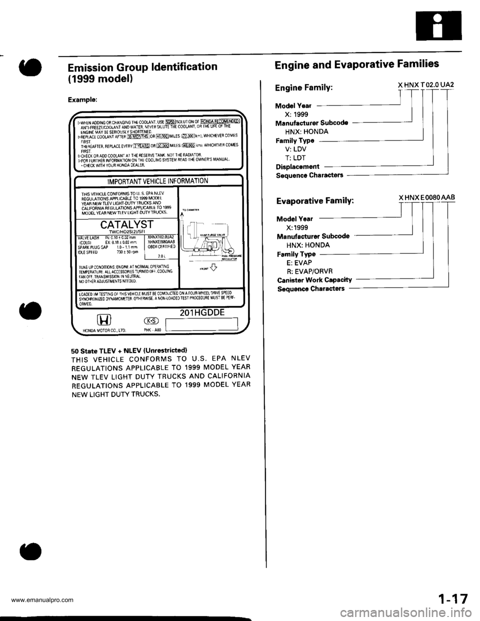
Emission Group ldentification
(1999 model)
Example:
50 state TLEV + NLEV {Unrestricted}
THIS VEHICLE CONFORMS TO U.S. EPA NLEV
REGULATIONS APPLICABLE TO 1999 MODEL YEAR
NEW TLEV LIGHT DUTY TRUCKS ANO CALIFORNIA
REGULATIONS APPLICABLE TO 1999 MODEL YEAR
NEW LIGHT DUTY TRUCKS.
'.WNEN AOO NG OR CNANGINC THE COOLANT. USE @SOLU I ON Of FONOA U-ECo-q.�NOEDImcrtniuvcoourr mo wlttt NEVEF oILLJTE THE CooLANT,0RTHE LIFE 0F TNE
"Eifil:$o""niii?i,THffi ffi'"R @ M LEs lmo rhl, wNrcHEVEn coMEs
i'lrt^t orrrr, ^,r*a, rurr"* os @ M LEs 1@ kmr wNICHEVER coMEs
}CNECK OR ADD COOLANT AT THE RESER!'E TAN( NOT IHE NADIATOSDFOfi fWTHEF NFORMATION ON THE COOL NC SYSTEM READ THE OWNER'S MANUAL'' CHECK WIIH YOUS HONOA OEALER.
GD
IMPORTANT VEHICLE INFORMATION
THIS VEHICLE CONFOAMSTOU. S EPA NLEVFEGULANONS APPLICCBLI TO 1999 MOD€LYEA8 NEW TIEV LIGHT DUTY ]nUCKS ANDCALIFORNIA REGULATIONS APPLICASLE IO 19S9MOOEL YEAR NEW TLEV LIGHT DUTY IFIJCKS,,|F --'-
Ll: .-.-,1
I rFrll\=#_H*
CATALYST
VALVE IASN lN:010r0.02 mmlCoLDj EX 0131002 mmSPA8K PLUG GAP 10- l l nmIDLE SPEED 130 t 5{ rPmOBDIICERT]ATD
201
TUNE I]PCONDIIIONS INGINEAT NOBTEI\'PERATUR€ ATL ACCESSOS ES TLJRNFAN OFf IRANSMSSION N NEL]TMLNO OINER ADJUSTMTNTS NEEOEO.
JL
Iooro nr tist rc orn svtncrE MUsT BE coMoufitooNArounwNEElDslvE SPEEDiitriunor mo ovuvo uenn orr Enw sE a NoN.loaDE D rEsr PRoCE ouRE MU sT 8E Pf Rr-
Engine and Evaporative Families
Engine Family:X HNX T02,O UA2
Model Year
X:1999
Manutao{urer Subcode
HNX: HONDA
Family Type
V: LDV
T: LDT
Displacoment
Saquence Charactors
Evaporative Family:X HNX EOO8OAAB
Model Yoal
X:1999
Manutacturar Subcode
HNX: HONDA
Family Typo
E: EVAP
R: EVAP/ORVR
Canbter Work Capacity
S€quonce Chartsters
1-17
www.emanualpro.com
Page 66 of 1395

lgnition System
5.
lgnition Timing Inspection and Setting
2.
1.Check the idle speed, and adjust it if necessary (see
section 1 1).
Pull out the service check connector 2P (BRN and
BLK wires) from the connector holder located under
the dash on the front passenger side, then connect
the scs service connector (P/N 07PAz - 0010100) to
it.
Start the engine. Hold the engine at 3,000 rpm with
no load (A/T in N or E, Mff in neutral) until the
radiator fan comes on, then let it idle.
Connect the timing light to the No. I ignition wire,
then point the light toward the pointer on the timing
belt cover.
Check the ignition timing in no load conditions:
headlights, blower fan, rear window defogger, and
air conditioner are not operating.
lgnition Timing:
M/T: 16" 12" BTDC (RED) idling in neutral
AlTt'16" !2" BTDC (RED) idling in E or E
CRANKSHAFTPULLEY
4-16
6. lf necessary, adjust the ignition timing as follows.
Loosen the distributor mounting bolts, and turn the
distributor ignition (Dl) housing counterclockwise to
advance the timing or clockwise to retard the tim-
t no,
7.
8.
MOUNTING BOLTS24 N.m {2.4 kgf m, 17 lbtft}
Tighten the distributor mounting bolts, and recheck
the ignition timing.
Disconnect the SCS service connector from the ser-
vice check connector.
To RETARD
www.emanualpro.com
Page 78 of 1395
Gharging System
Troubleshooting (cont'd)
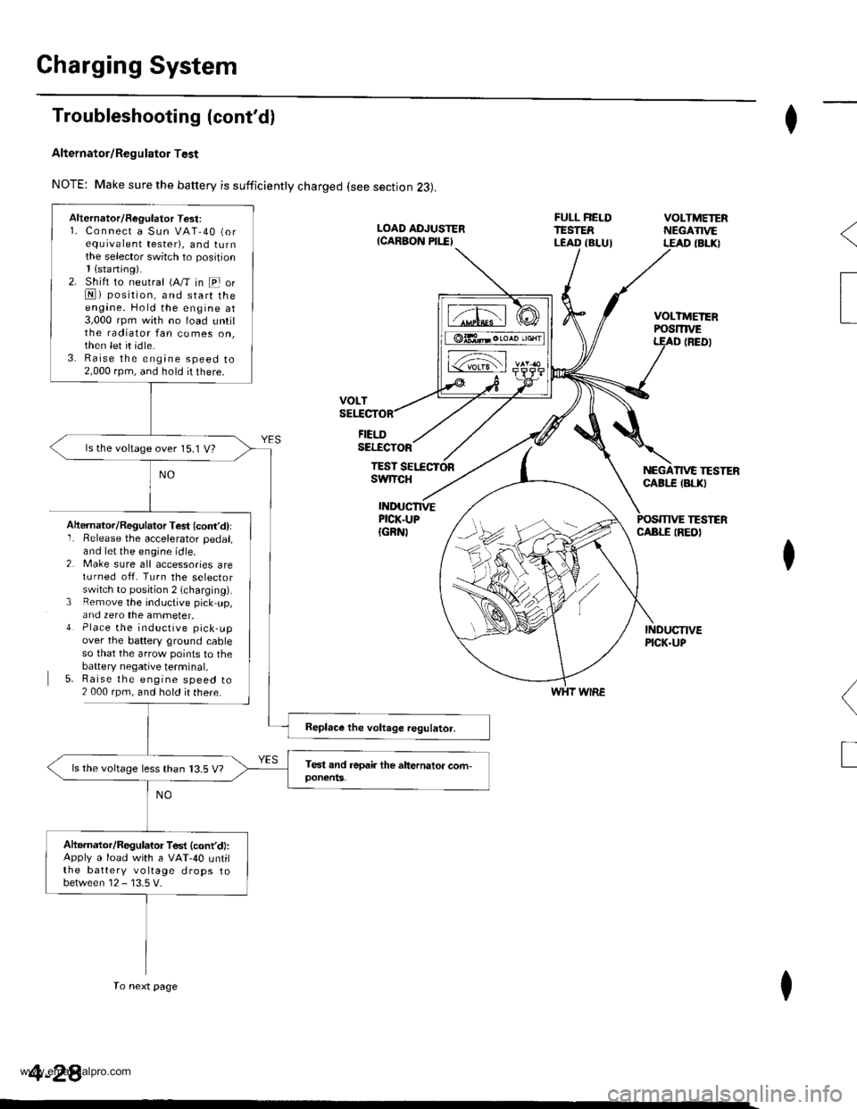
Alternator/Regulator Test
NOTE: Make sure the battery is sufficiently charged (see section 23).
FIELDSELECTOR
TESTswtTcH
I
VOLTMEIERPOSmVEt
NEGATIVE TESTERCABI.E {BLKI
(BED)
TESTERINDUCTIVEPICK.UP{GRN)CABLE IREDIAhernator/Regulator Test (cont'd)lI� Release the accelerator pedal,and let the engine idle.2 Make sure all accessories areturned off. Turn the selectorswitch to posjtion 2 (charging).3 Remove the inductive pick up,and zero the ammeter.{ Place the inductive pick-upover the battery ground cableso that the arrow points to thebaftery negative terminal.5. Raise the engine speed to2 000 rpm, and hold ir there.
I
(
T
I
WHT WIRE
Alternator/Regulator Test:1. Connect a Sun VAT-40 (orequrvalent tester), and turnthe selector switch to position1{sraning).2. Shift to neutral (A/T in E orN) position, and start theengane. Hold the engine at3,000 rpm with no load untilthe radiator fan comes on,then let it idle.3. Raise the engine speed to2,000 rpm, and hold it there.
ls the voltage over 15.1 V?
ls the voltage less than 13.5 V?
Altarnator/Regulator Test (cont'd:Apply a load with a VAT-40 untilthe battery voltage drops tobetween 12 - 13.5 V.
To next page
4-28
www.emanualpro.com
Page 213 of 1395
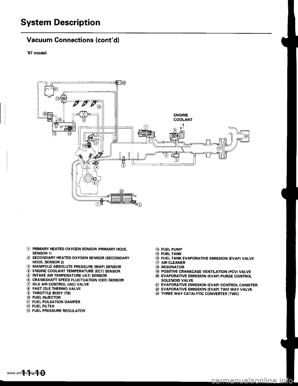
System Description
Vacuum Connections (cont'dl
'97 model:
ENGINECOOLANT
ITr|ll
O PRIMARY HEATED oxYGEN sENsoR {PRIMARY Ho2s,SENSOR lt
O SECONDARY HEATED oxYGEN sENsoR {SECoNDARYHO2S. SENSOR 2l€) MANIFOLD ABSOLUTE PRESSURE (MAPI SENSOR@ ENGINE cooLANT TEMPERATURE {EcT} sENsoRO INTAKE AIR TEMPERATURE (IAI} sENsoR@ CRANKSHAFT SPEED FLUCTUATION ICKFI SENSORO |DLE ArR coNTRoL {tAc)vALvE@ FAST IDLE THERMo vALvEO THRoTTLE EoDY ITB)@ FUEL INJEcTonO FUEL PULSATIoN oAMPER@ FUEL FILTEn(} FUEL PRESSURE REGULATOR
FUEL PUMPFUEL TANKFUEL TANK EVAPORATIVE EMISSION (EVAPIVALVEAIR CLEANERRESONATORPOSITIVE CRANKCASE VENTILATION {PCVI VALVEEVAPORATIVE EMISSION {EVAP} PURGE CONTROLSOI.'ENOID VALVEEVAPORATIVE EMISSION {EVAP) CONTROL CANISTEREVAPORATIVE EMISSION {EVAPI TWO WAY VALVETHREE WAY CATALYTIC CONVERTER (TWC)
@(D(D
o@(}
@
@@@
1 1-10
www.emanualpro.com
Page 215 of 1395
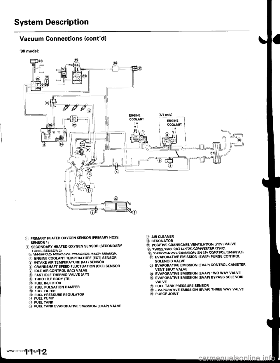
System Description
I
I
I
Vacuum Connections (cont'dl
'98 model:
C PRIMARY HEATEO OXYGEN SENSOR (PRIMARY HO2S,
SENSOR 1)(, SECONDARY HEATEO OXYGEN SENSOR ISECONDARYHO2S, SENSOR 2)(!)\\\\ss\SNBSS\\\ETRESS\RE\\NQ\SE\SSR
G) ENGINE COOLANT TEMPERATUBE (ECT) SENSOR
O INTAKE AIR TEMPERATURE {IAT} SENSOR
@ CRANKSHAFT SPEED FLUCTUATION (CKFI SENSOR
O IDLE AIR CONTROL (IAC) VALVE
@ FAST IDLE THERMO VALVE (A/T)
O THROTTLE BODY (TBI(0) FUEL INJECTOR.1' FUEL PULSATION DAMPER.14 FUEL FILTER(i FUEL PRESSURE REGULATOR14 FUEL PUMP(D FUEL TANK@ FUEL TANK EVAPORATIVE EMISSION {EVAPI VALVE
C] AIR CLEANER(O RESONATOR1iC POSITIVE CRANKCASE VENTILATION (PCV) VALVE
6 \$REE$IN gN NL$\C CON\ER\ER (TNC\
ti q rpos,xr E qN
ssros \E aP cqN\RoLcaNtsr€R
@ EVAPORATIVE EMISSION IEVAP) PURGE CONTROL
SOLENOID VALVEq3 EVAPORATIVE EMISSTON IEVAP} CONTROL CANISTER
VENT SHUT VALVE
@ EVAPORATIVE EMISSION (EVAP) TWO WAY VALVE
€i EVAPORATIVE EMISSION {EVAP) BYPASS SOLENOID
VALVE
€9 FUEL TANK PRESSURE SENSOROi EVAPORATIVE EMISSION {EVAP) THREE WAY VALVE
Qd PURGE JOINT
G/T only)
f
-i*'";-t
COOLANT Jt
U
11-12
www.emanualpro.com
Page 217 of 1395
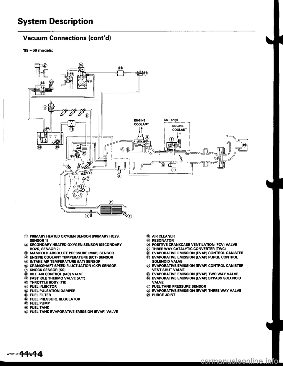
System Description
Vacuum Connections (cont'dl
'99 - q) models:
ENGINECOOLANT
t
o
o
o@
o@@@@@@@@@(t
PRIMARY HEATED OXYGEN SENSOR IPRIMARY HO2S,SENSOR 1lSECONDARY HEATED OXYGEN SENSOR {SECONDARYHO2S. SENSOR 2lMANIFOLD ABSOLUTE PRESSURE (MAPI SENSORENGINE COOLANT TEMPERATURE IECN SENSORINTAKE AIR TEMPERATURE IIATI SENSORCRANKSHAFT SPEED FLUCTUATION {CKF) SENSORKNOCK SENSOR (KS}
IDLE AIR CONTROL IIACI VALVEFAST IDLE THERMO VALVE {A/T}THROTTLE BODY (TB}
FUEL INJECTORFUEL PULSATION DAMPERFUEL FILTERFUEL PRESSURE REGULATORFUEL PUMPFUEL TANKFUEL TANK EVAPORATIVE EMISSION (EVAPI VALVE
AIR CLEANERRESONATORPOSITIVE CRANKCASE VENTILATION (PCV} VALVETHREE WAY CATALYTIC CONVERTER ITWCIEVAPORATIVE EMISSION {EVAPI CONTROL CANISTEREVAPORATIVE EMISSION IEVAPI PURGE CONTROLSOLENOID VALVEEVAPORATIVE EMISSION {EVAPI CONTROL CANISTEFVENT SHUT VALVEEVAPORATIVE EMISSION IEVAPI TWO WAY VALVEEVAPONANVE EMISSION {EVAPI AYPASS SOLENOIDVALVEFUEL TANK PRESSURE SENSOBEVAPORATIVE EMISSION IEVAPI THREE WAY VALVEPURGE JOINT
@@@@@@
@
@@
@@@
11-14
www.emanualpro.com
Page 266 of 1395

Troubleshooting
Troubleshooting Procedures (cont'dl
Symptom Chart
Listed below are symptoms and probable causes for problems that DO NOT cause the Malfunction Indicator Lamp (MlL) tocome on. lf the MIL was reported on, go to page 11-60.Troubleshoot each probable cause in the order listed (from left to right) until the symptom is eliminated,The probable cause and troubleshooting page reference can be found below.
Other Probable Causes for an engine that will not start:- Compression- Intake air leakage- Engine locked up- Timing belt- Starting system- Overheating- Battery
SYMPTOMPROBABLE CAUSE
Engine will not sta rt4, 2,3,5,20, 't5, 1
Hard starting2, 4, 12,17, 14, 't9
Cold fast idle too low7, a,9, 6, 17
Cold fast idle too high7,8,9,11,10
ldle speed fluctuates9,7,8, 't1, 10
Misfire or rough runningTroubleshoot for misfire on pages '11-126, 1|21LOl/\/ power2, 10,11, 13, '17, 18,20
Engine stalls2, 4, 12,1,20,9,5, 't6
Probable Cause List (For the DTC Ch8rt, see page ll-75.)
Probable CausePageSystem
Engine controt ruoaute (ecvtffi'I11-42
I 1-178Fuel oressure
PGM-Fl main relav
lgnition system
Crankshatt Position/Top Dead Center/Cylinder position sensor circuit
Intake Air Temperature (lAT) sensor ctrculr
ldle Air Control (lAC) Vatve
Fast idle thermo valve
ldle speed adjustment
Throttle body
Throftle cable
Manifold Absolute P."""rr"ffi
Throftle Position (TP) sensor
Barometric pressur" (gnno-
Ay'T gear position signal
Brake switch signal
Air Cleaner
Three Way Catalytic Converter (TWC)
Evaporative emission (EVAP) control
Contaminated fuel
1 1- 187
Section 4
5't1-'t31,146
6I '�t-95
711-152
81'l-168
1 1- 169
1011-196'1111-'194
12'1 'l -90
1 1- 103
1411-137
15Section 14
161 1- 166
17r 1-194
181 1,199'1911-203
20
11-64
www.emanualpro.com
Page 268 of 1395

Troubleshooting
Troubleshooting Procedures (cont'd)
DataDescliptionOperating ValueFreezo Data
HO2S
Feedback
Loop Status
Loop status is indicated as "open" or "closed".
Closed: Based on the HO2S output, the ECM/pCM deter-mines the airlfuel ratio and controls the amount ofinjected fuel.
Open: ignoring HO2S output, the ECM/pCiM refers to sig,nals from the TP, MAP, and ECT sensors to control theamount of injected fuel.
At idle speed: closed
YES
Short Term
Fuel Trim
The airlfuel ratio correction coefficient for correcting theamount of injected fuel when HO2S feedback is in theclosed loop status. When the signal from the HO2S isweak, short term fuel trim gets higher, and the ECM/PCMincreases the amount of injected fuel. The airlfuel ratiogradually gets richer, causing a higher HO2S output.Consequently. the short term fuel trim is lowered. andthe ECM/PCM reduces the amount of injected fuel.This cycle keeps the airfuel ratio close to the stoichio-metric ratio when in closed looD status.
t:20y"
YES
Long Term
Fuel Trim
Long term fuel trim is computed from shon term fueltrim and indicates changes occuring in the fuel supplysystem over a long period.
lf long term fuel trim is higher than 1,00. the amount ofinjected fuel must be increased. lf it is lower than L00.the amount of injected fuel must be reduced.
! 20%
Intake Air
Temperature
(IAT)
The IAT sensor converts intake air temperature into volt-age and signals the ECrU/PCM. When intake air tempera-ture is low, the internal resistance of the sensorincreases, and the voltage signal is higher.
With cold engine:
Same as ambient temper-
ature and ECTYES
Throttle
Position
Based on the accelerator pedal position, the openingangle of the throttle valve is indicateo.At idle speed:
approx. 10%
lgnition
Timing
lgnition timing is the ignition advance angle set by theECM/PCM. The ECM/PCM matches ignition timing to thedriving conditions.
At idle speed: 16'1 4.
BTDC with the SCS ser-
vtce connector connected.
NO
Calculated
Load Value(cLV)
CLV is the engine load calculated from the MAp data.At idle speed:
2A - 410/o
At 2,500 rpm with no load:
13 - 260/o
YES
_
1 1_66
www.emanualpro.com