1999 HONDA CR-V Air cool
[x] Cancel search: Air coolPage 401 of 1395
Emission Control System
System Description
The emission control system includes, a Three Way
Catalytic Converter {TWC), Positive Crankcase Ventilation
(PCV) svstem and Evaporative Emission (€VAP) Control
system. The emission control system is designed to meet
federal and state emission standards.
Tailpipe Emission
Inspsction
!@ Do not smoke during this procsdura. Keep
any open tlame away from your work area.
1. Start the engine. Hold the engine at 3,000 rpm with
no load (in Park or neutral) until the radiator fan
comes on, then let it idle,
Connect a tachometer.
Check and, if necessary, adjust the idle speed, (see
page 11-169, 170).
Warm up and calibrate the CO meter according to the
meter manufacturer's instructions.
Check idle CO with the headlights, heater blower, rear
window defogger, cooling fan, and air conditioner off.
(Canada) Pull the parking brake lever up. Start the
engine, then check that the headlights are off.
CO meter should indicate 0.1% maximum.
4.
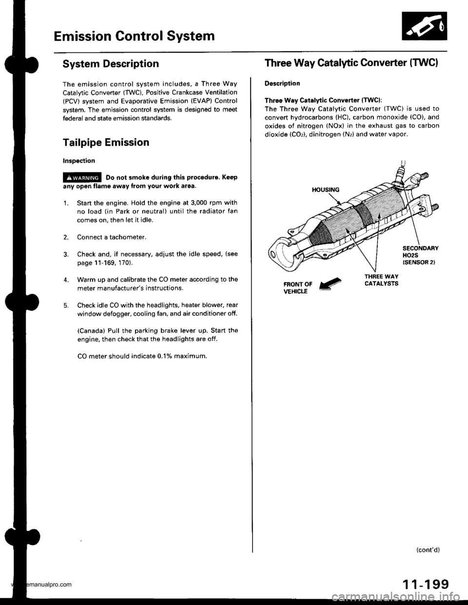
Three Way Catalytic Converter (TWCI
DsscriDtion
Three Way Catalytic Convertsr lTwcl:
The Three wav Catalvtic Converter (TWC) is used to
convert hydrocarbons (HC), carbon monoxide (CO), and
oxides of nitrogen (NOx) in the exhaust gas to carbon
dioxide (COr), dinitrogen (Nr) and water vapor,
{cont'd)
1 1-199
www.emanualpro.com
Page 405 of 1395
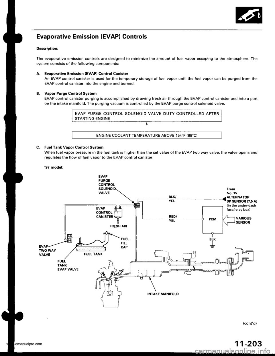
EVAP PURGE CONTROL SOLENOID VALVE DUTY CONTROLLED AFTER
STARTING ENGINE
ENGINE COOLANT TEMPERATURE ABOVE 154"F (68'C)
Evaporative Emission (EVAP) Controls
Description:
The evaporative emission controls are designed to minimize the amount of fuel vapor escaping to the atmosphere. The
system consists of the following components:
A. Evaporative Emission (EVAPI Control Canister
An EVAP control canister is used for the temporary storage of fuel vapor until the luel vapor can be purged from the
EVAP control canister into the enqine and burned.
B. Vapor Purge ConirolSystem
EVAP control canister purging is accomplished by drawing fresh air through the EVAP control canister and into a pon
on the intake manifold. The purging vacuum is controlled by the EVAP purge control solenoid valve.
C. Fuel Tank Vapor Control System
When fuel vapor pressure in the fuel tank is higher than the set value of the EVAP two way valve, the valve opens and
regulates the flow ot fuel vapor to the EVAP control canister.
'97 model:
EVAPPURGECONTROL
VALVEFromNo. 15BLK/ /ALTERNATORYEL I sP SENSOR r7.s At(in the under-dashfuse/relay box)
VARIOUSSENSORFEESH AIF
BLK
I
FUEI- TANK
(cont'd)
11-203
INTAKE MANIFOLD
www.emanualpro.com
Page 425 of 1395
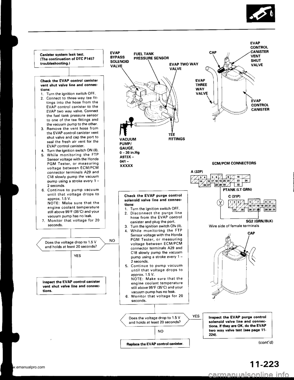
Canbter system leak test
{The continuation of DTC P1457
trouble3hootin9.)
Chock the EVAP control canistervent shut valve line and connoc'
tonS:1. Turn the ignition switch OFF
2. Connect to three'way tee fit_
tings into the hose from the
EVAP control canister to the
EVAP two way valve. Connect
the fuel tank pressure sensor
to one of the tee fittings and
the vacuum PumP to the other'
3. Remove the vent hose from
the EVAP control canister vent
shut valve and cap the Pon to
seal the fresh air vent Ior the
EVAP control canister.4. Turn the ignition switch ON (ll).
5. While monitoring the FTP
Sensor voltage with the Honda
PGM Tester, or measurangvoltage between ECM/PCM
connector terminals A29 and
C18 slowly PumP the vacuumpump using a stroke every 1 -
2 seconds.6. Continue to PumP vacuum
until that voltage droPs to
approx. 1.5 V.NOTE: Make sure that the
engine coolant temPeraturestillabove 95'F (35'Cland Yourvacuum PumP has no leak
7. Monitor that voltage for 20
seconds.
Check the EVAP Pu.ge control
solenoid valve line and connec-
tions:1. Turn the ignition switch OFF.
2. Disconnect the Purge lane
hose from the EVAP control
canister and Plug the Port3. Turn the ignition switch ON (lli.
4. While monitoring the FTP
Sensor voltage with the Honda
PGM Tester, or measuringvoltage between ECM/PCM
connector terminals A29 and
Cl8 slowly PumP the vacuumpump using a stroke every 1 -
2 seconds.5. Continue to pump vacuum
until that voltage droPs to
approx. 1-5 V.NOTE: Make sure that the
engine coolant temPeraturestill above 95'F (35"C) and Yourvacuum pump has no leak-
6. Monitor that voltage tor 20
seconds.
Doesthe voltage drop to 1.5 V
and holds at least 20 seconds?
lGp€ct the EVAP control cani3tel
vent 3hut valvo line and connec_
tion5.
Inlpect tho EVAP Putge control
solenoid valvo line and connec'
tion3. It th6y lro OK, do the EVAP
two way valve te3t (seo page 11-
2211.
Does the voltage drop to 1.5 V
and holds at least 20 seconds?
Reolace the EVAP conirol canister.
EVAPBYPASSSOLENOIDVALVE
FUEL TANK
EVAPCONTROL
VENTSHUTVALVE
EVAPCONTROLCANISTER
SENSOR
EVAP TWO WAYVALVE
EVAPTHREE
VALVE
ttrrL
ta
VACUUMPUMP/GAUGE,0 - 30 in.HgA973X -
041 -
XXXXX
FITTINGS
ECM/PCM CONNECTORS
A {32P)
PTANK ILT GRN)
c (31Pt
SG2 {GRN/BLK)
Wire side of female terminals
{cont'd)
11-223
www.emanualpro.com
Page 517 of 1395

Automatic Transmission
Special Tools . 14'2OescriptionGeneral Operation . .... 14 3Power Flow . . .. '14_6
Electronic Control System .. .. . . .. .14_15Hydraulic Control .. 14 24Hydraulic Flow....-....... .. . .... .. .. . 14_29Lock'up Syslem .. .'t4'39Electrical SystemComponenl Locdlrons 14 45
PCM Circuil Dragram (A/T Control Svstem)'97 Model ....................... . . .. - . ... .14-46'98Model ................. . ... .. .. .1450'99 00Models.... . .... . . . 1452
PCM Terminal Voltage/Measuring ConditionsA"/T Control System-'97Model ...... ..14'48A,/T Control System -'98 00 Models . . .. . . 14 54
Troubleshooting Procedures .. ..... ... - 14_56Svmotom to comoonent CharlEiectr,cal Syslem -'97 Model . . 14 60Electrical System -'98 - OO Models . .. . . 14_62Electrical Troubleshooting ('97 Model)Troubleshooting Flowaharts .... ..... . .. . . 14_64
Electrical Troubleshooting ('98 - 00 Models)Troubleshootinq Flowclt"n" .... . ....- . .14-93ElectricalTroublesliooting('99 00Models)Troubleshootino FlowchartO/D OFF Indicator Light Does Not Come On 14 131
O/D OFF Indicator Liaht On ConstantlY . . . .1!-132O/D OFF Indicator Light Does Not Come OnEven Though O/D Switch ls Pressed . .... - 14_133
Lock up Control Solenoid Valve A,/B AssemblyTest....................-......... . .14-135Replacement . .ll_135Shifr ControlSolenoid Valve Ay'B Assembl,Test .............................. . .. 14-136
Replacement..............- . .14'136Linear Solenoid AssemblYTest.............................................. .. .... . 14_137Replacement .. . 14138Marnshaftlcountershafl Speed SensorsReplacement ...-... 14_138A/T Gear Position SwitchTest ..........................-... . .. 14-139ReplacementA/T Gear Positionlndicator.................. 14-140
Valve Eodynepair ............................... ..... . . .. - . .. ... 14 192
Assembly .................... .. 1{_193
Valve CapsDesciiption....-........................ .. ...... 14194
tnspeition ................... .. 14' 195
N4ain Valve BodyDisassembly/lnspection/Reassemblv - ...... .. 14_196
Secondarv Valve BodYDisassemblv4nspectron/ReassemblY .. . 14 198
Reoulator Valve Bodvbisassembtv,lnspiction/Reassemblv . 14199
Servo EodvDisassembly/lnspection/Reassembly ... ....14'200
Lock'uo Valve BodYDis;ssembly/lnspection/Reassembly .... . 14_201
MainshaftDisassembly/lnspection/Reassembly .. .. .. ..14'202
Inspection ....-.............. ..11_203
Sealing RingsReilaceient ...... ..... . 14'204
CountershaftDisassembly/lnspection/Reassembly .. . . . . . 11-205
Disassembly/Reassemb|y . . ........ ...... . .. 14_206Inspedron ................ . .... . 14 207
One wav ClutchDisassembly/lnspection/ReassemblY ... 11_209
Sub-shaftDisassembly/lnspection/Reassembly ... . .. . 14-210
oisassembly/Re6ssembly . . ... .-...... . . ..14-211
Sub-shaft BearingsReplacement .......14'212
Clutchllfustrated Index .......... . . .14-213
Disassembly .... .. .....14-216Reassembfy .... . .. .. . 14'218
Differentialllfustrated Index " 14-222Backlash Inspection . .... . .14'223
Bearing Repiacement .. 11-223
Differe-ntial Carrier Replacement .. .. . . . .. ..11-2?4
OifSeal Replacement. . .. 14'225
Side Clearance lnspection . . - .. ... . - ...... . .. 11'226
Transmission Housing BearingsMainshaJVCountershaft EearingsRepfacement .......14221Sub'siralt Eearing Replacement . . . . . . . . . ..11'224
Toroue Converter Housing BearingsMainshattEearing/OilSe6lReplacement . .. l4229
Countershaft Bea;ing Replacement.. .... .. ..14-230
Input Test - '97 - 98 ModelsInput Test '99 - 00 Models
Symptom to-Component ChartHydraulic System ...............
Checking
Removal ...,lllustrated Index (4WD)
Interlock SystemInterlock ControlUnit lnputTest. -..... -.. .... . - 14 144* Key Interlock Solenoid Test .- .. . . . - . . . ..... 14_146* Shift Lock Solenoid Test ..............-.-. . .. . ... .... 14 147*Shift LockSolenoidReplacement...... .. . .. .. 14 148* park pin Switch Test ......... 14 119' Park Pin Switch Replacement- '97 - 98 Models ....... 14-150* Park Pin Swirch/Over Drive (O/Di SwitchReplacemenl '99-00Models . .. 14_151over-Drive (O/D) Switch {'99 00 [4odels]Test........_..................... .......14-152Hydr.ulic System
..............._............... t4 142.................................. 14-143
Control Lever AssemblyR6placement ......,.,Reverse ldler Gear
lllustrated lndex
.......... 14-230
14 231
11-231
1nsta1|ation ..................Park StopInspeclion/AdjustmenlTransfer AssemblY.......14.232
RoadTest.............-.... ........ .StallSpeedTest ....._........................ ....... 14-159Fluid Level......_................... 14'160
Disessembly .................... 14-235Transfer Drive Gear BearingReplacementTrans{er Driven Gesf Shaft BearingReplacementTransfer Housing Roller BearingReplacementTransfer Cov€r A Bearing Outer RaceReplacementTransfer Housing Bearing Outer RaceReplacement ......-..,,,,,.....ReassemblvTransmassaonBeassembly ... -.. .... .14 250
Torque Converier/Drive Plate . .-. .... .. . ... .....14_258
Transmissionlnstatlation .................. ....... 14'259
Cooler Flushing . . ......11-261ATF Cooler HosesConnection.................. ....... 14-266I Shift LeverRemoval/lnstallation . .. 14'261
Disassemblv/Reassemblv - '97 - 98 Models . . 14_264
Disassembli/Reassemblv -'99 - 00 Models . 14-269
Over'Orive (O/D) Switch WireClearanceAdjustment. - ... . . . .. .. . 14'270
Detent Spring Replscement . . -.. ... .14'271*Shift CableAdiustment ....... 14'272
Repfacement.............. . 11'273
14 15711-237
11-237
14-238
$-234
11-23914-240
Transmigrion
Inspeclron ....., ...........Transfer AssemblyRemova1,.,,,..............,lnstallalion ........... .. ...Transmission
14 164
14-16514,167
14-169
End Cover/Transmissio . 14'174Transmission Housing .... ... .. . . .... .. 14-176Torque Converter Housingly'alve Body.. - ... -. 14 178
lllustrated lndex (2WD)End Cover/Transmissio ....... 14 180Transmission Housing . . ... . .. .... ... 14'182Torque Convener Housing/r'alve Body ......- 14-184
End CovefRemovat ...................... ....... 14'186Transmission HousingRemoval ...................... .. 14_188Torque Convener HousingA/alve BodYRemovat ................-..... .-..... 14-190
www.emanualpro.com
Page 706 of 1395
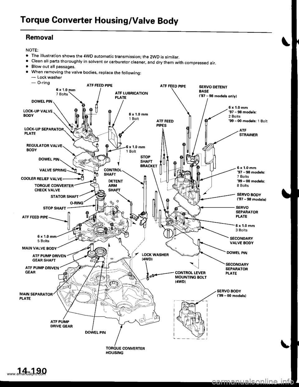
Torque Converter Housing/Valve Body
Removal
NOTE:
. The illustration shows the 4WD automatic transmission; the 2WD is similar.' cleanall parts thoroughry in sorvent or carburetor creaner, and drythem with compressed air.. Blow out all passages.
. When removing the valve bodies, replace the following:- Lock washer- O-ringATF FEED PIPESERVO DETENTBASE137 - 98 models only)
DOWEL PIN
LOCK.UP VALVEBOOY
6x1.0mm'97 - 98 models:2 Bolts'99 - 00 modeb: 1 Bolt
LOCK.UP SEPARAPLATE
REGULAIOR VALVEBOOY
ATFSTRAINER
DOWEL PIN
COOLER RELIEF VALVE
6x1.0mm37 - 98 models:7 Bolts'gg - 0O models:8 Bolts
SERVO BODY137 - 98 modelsl
SERVOSEPARATORPLATE
TOROUE CONVERTERCHECK VALVE
STATOR SHAFT
O.RING
5x1.0mfi3 Bolts
SECONDARYVALVE BODY
MAIN VALVE BODY
6x 1.05 Bolts
ATF PUMP ORIVENGEAR SHAFT
DOWEL PIN
ATF PUMP DRIVENGEAR
\
CONTROL LEVERMOUNTING BOLT{awD)
SECONDARYSEPARATORPLATE
14-190
www.emanualpro.com
Page 715 of 1395
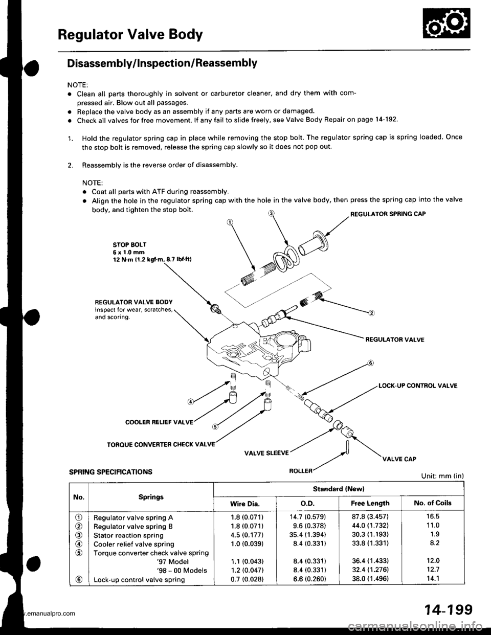
Regulator Valve Body
Disassembly/lnspection/Reassembly
NOTE:
o Clean all parts thoroughly in solvent or carburetor cleaner, and dry them with com-
pressed air. Blow out all passages.
. Replace the valve body as an assembly if any parts are worn or damaged.
. Checkall valvesforfree movement. lf anyfail toslidefreely, see Valve Body Repair on page l4-192.
'1. Hold the regulator spring cap in place while removing the stop bolt. The regulator spring cap is spring loaded Once
the stop bolt is removed, release the spring cap slowly so it does not pop out.
2. Reassembly is the reverse order of disassembly.
NOTE:
. Coat all parts with ATF during reassembly.
. Align the hole in the regulator spring cap with the hole in the valve body, thenpress the spring cap into the valve
REGULATOR SPSING CAPbody, and tighten the stop bolt.
STOP BOLT6x1.0mm12 N.m 11.28.? tbt.fil
REGULATOR VALVE BODYlnspect for wear, scratches,ano scoflng.
REGULATOR VALVE
No,SpringsStandard {New}
wire Dia.o.D.F ee LengthNo. ot Coils
o
@
@,6
a,
Regulator valve spring A
Regulator valve spring B
Stator reaction spring
Cooler relief valve spring
Torque converter check valve spring'97 Model'98 - 00 Models
Lock-up control valve spring
1.8 (0.071)
1.8 (0.071)
4.5 (0.177)
1.0 {0.039)
1.1 (0.043)
1.2lO.O47l
0.7 t0.028)
14.7 (0.579)
9.6 (0.378)
35.4 (1.394)
8.4 {0.331)
8.4 (0.331)
8.4 (0.331)
6.6 (0.260)
87.8 (3.457)
44.0 t1.7321
30.3 (1.193)
33.8 (1.331)
36.4 (1.433)
32.4 11.2761
38.0 (1.496)
'11.0
1.9
't2.0
12.7
14.'l
14-199
www.emanualpro.com
Page 773 of 1395
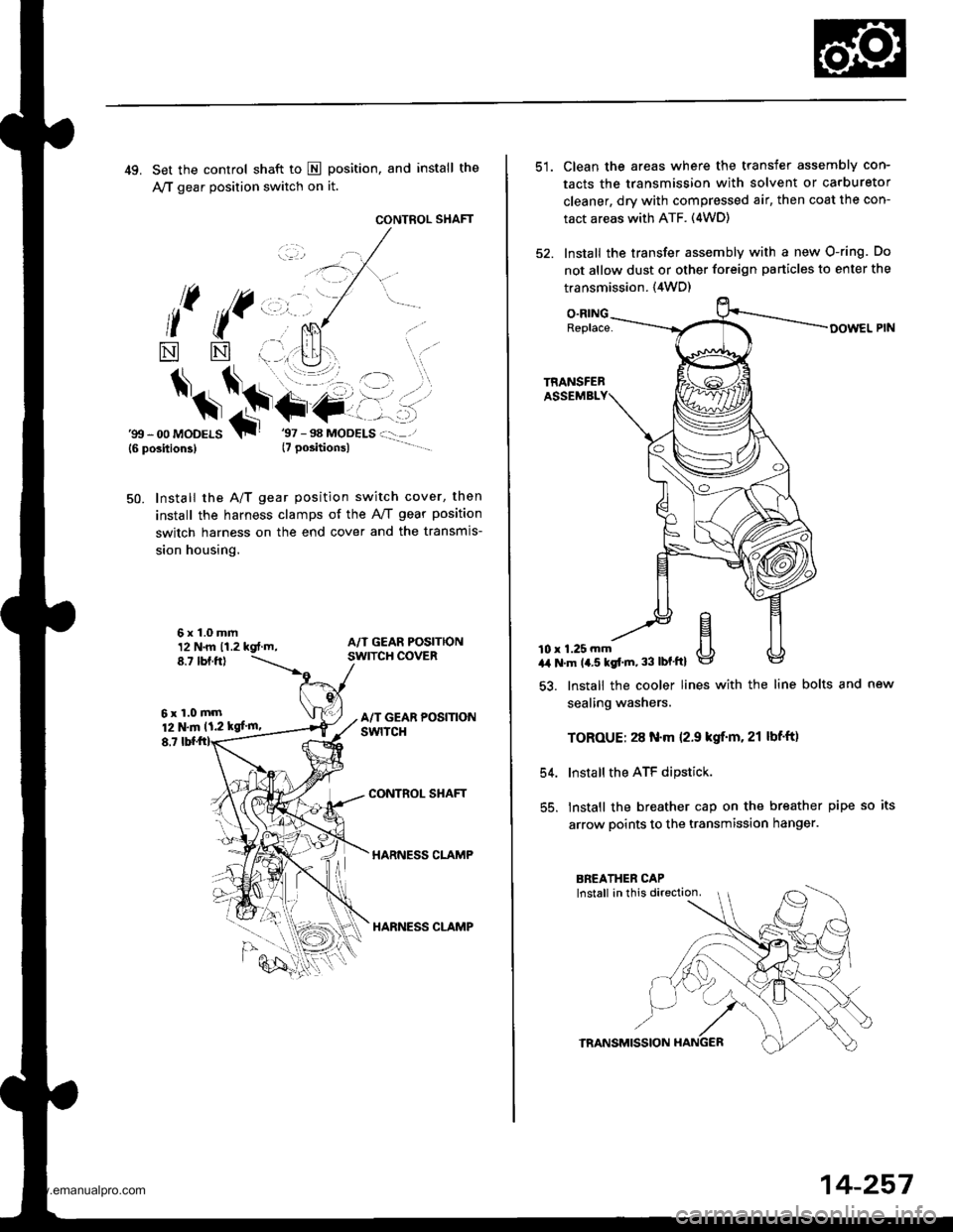
49. Set the control shaft to E position, and install the
A,/T gear position switch on it.
CONTROL SHAFT
l( ((,,, ,.
*
$*\.t+-
NN
6x1.0mm12 N.m 11.2 kgt.m,8.7 tbf.ftl
6xl.0mm12 N.m 11.2 kgf'm,
8,7
'gtt - 00 MoDELS{6 position3}T
Install the A/T gear position switch cover, then
install the harness clamps of the AviT gear position
switch harness on the end cover and the transmis-
sion housing.
50.
CONTROL SHAFT
HARNESS CLAMP
HARNESS CLAMP
Clean the areas where the transfer assembly con-
tacts the transmission with solvent or carburetor
cleaner, dry with compressed air, then coat the con-
tact areas with ATF. (4WD)
Install the transfer assembly with a new O-ring. Do
not allow dust or other foreign particles to enter the
transmission. {4WD)
O.RINGReplace-
10 r 1.25 mma,a N'm 14.5 kgt'm, 33 lbf'ftl
54.
55.
lnstall the cooler lines with the line bolts and new
sealing washers.
TOROUE: 28 N.m 12.9 kgif'm. 21 lbf'ft)
Install the ATF dipstick.
lnstall the breather cap on the breather pipe so its
arrow points to the transmission hanger.
TRANSMISSION
14-257
www.emanualpro.com
Page 776 of 1395
Transmission
Installation (cont'dl
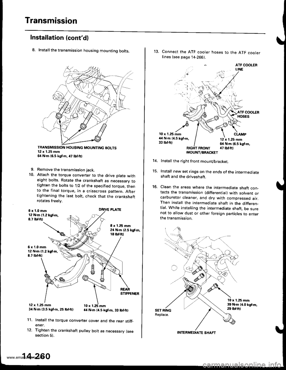
8. Install the transmission housing mounting bolts.
TRANSMISSION HOUSING MOUNTING BOLTS12 x 1.25 mm54 N.m 16,5 kgf.m, a7 lbtftl
9. Remove the transmission jack.
10. Attach the torque convener to the drive plate witheight bolts. Rotate the crankshaft as necessarv totighten the bolts to 'll2 of the specified torque, thento the final torque, in a crisscross pattern. Aftertightening the last bolt. check that the crankshaftrotates freelv.
6x1.0mln12 N.m (1.2 tgt m,8.t lbf.frl
6x1.0mm12 N.m {1.219{.m,8.7 tbtft,
12 x t.25 mm34 N.m 13.5 kgf.rn,25 lbf.ft)
8 x 1.25 mm2a N.m 12.5 kgf'm,18 tbt.ftl
DRIVE PLATE
STIFFENER
44 N.rn (4.5 kgt m, 33 lbtftl
11.
12.
Install the torque convener cover and the rear stiff_ener.
Tighten the crankshaft pulley bolt as necessary (seesection 5).
14-260
13. Connect the ATF cooler hoses to the ATF coolerlines (see page 14-266).
. ATF COOLERLINE
'i 'l'r',:,.) -
10 x 1.25 mm44 N.m (4.5 kgf.m,33 tbtftl
CLAMP
12 x 1.25 mm64 N.m 16.5 kg{.m,a7 tbt.ftlFRotrtT
15.
16.
't 4.
SET RINGReplace.
MOUNT/ARACKET
Install the right front mounvbracket.
Install new set rings on the ends of the intermediateshaft and the driveshaft.
Clean the areas where the intermediate shaft con_tacts the transmission {differential) with solvent orcarburetor cleaner, and dry with compressed air.Then install the intermediate shaft in the differen_tial, While installing the intermediate shaft, be surenot to allow dust or other foreign panicles to enterthe transmission.
l0 x 1.25 mm39 N.m 14.0 kgt.n,29 tbf.ftl
INTERMEDIATE SHAFT
www.emanualpro.com