Page 302 of 1395

PGM-FI System
Engine Coolant Temperature (ECTI Sensor {cont'd)
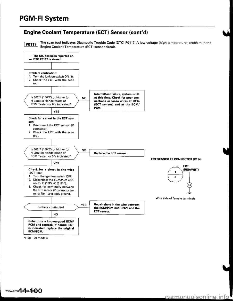
[F011' The.scan tool indicates Diagnostic Trouble Code (DTC) P0117: A low voltage (high temperature) problem in the: Engine Coolant Temperature (ECT) sensor circuit.
ECT SENSOR 2P CONNECTOR {C114I
Wire side of female terminals
- The MIL has been rooortod on.- DTC ml17 is sto.od.
Problem verification:1. Turn the ignition switch ON {ll).2. Check the ECT with the scantool,
Intermittont f.ilure, sysiom is OKat thk time. Check for poor con-nections or loo3e wire3 at C1lil(ECT sensorl and et the ECM/PCM.
ls 302"F (150'C) or higher (or
H Limit in Honda mode otPGM Tester) or 0 V indicated?
Check for a Bhort in the ECT sen-301:'1. Disconnect the ECT sensor 2Pconnefior,2. Check the ECT with the scantool.
ls 302"F (150"C)or higher (or
H-Limit in Honda mode ofPGM Tester) or 0 V indicated?
Check for r shorl in the wirs(EgT linel:1. Turn the ignition switch OFF.2. Disconnect the ECM/PCM con-nector D (16P), (C (31P)*1.3. Check tor continuity betweenthe ECT sensor 2P connectorterminal No. 1 and bodyground.
Repair short in the wir€ betweenthe ECM/FCM (D2, C26rl ,nd th6ECT senaor.
ls there continuity?
Substitute a known-good ECM/PCM and recheck. It normal ECTi! indicatod, replaco the oiiginalECM/PCM.
*:'98 - 00 models
1-1
www.emanualpro.com
Page 303 of 1395

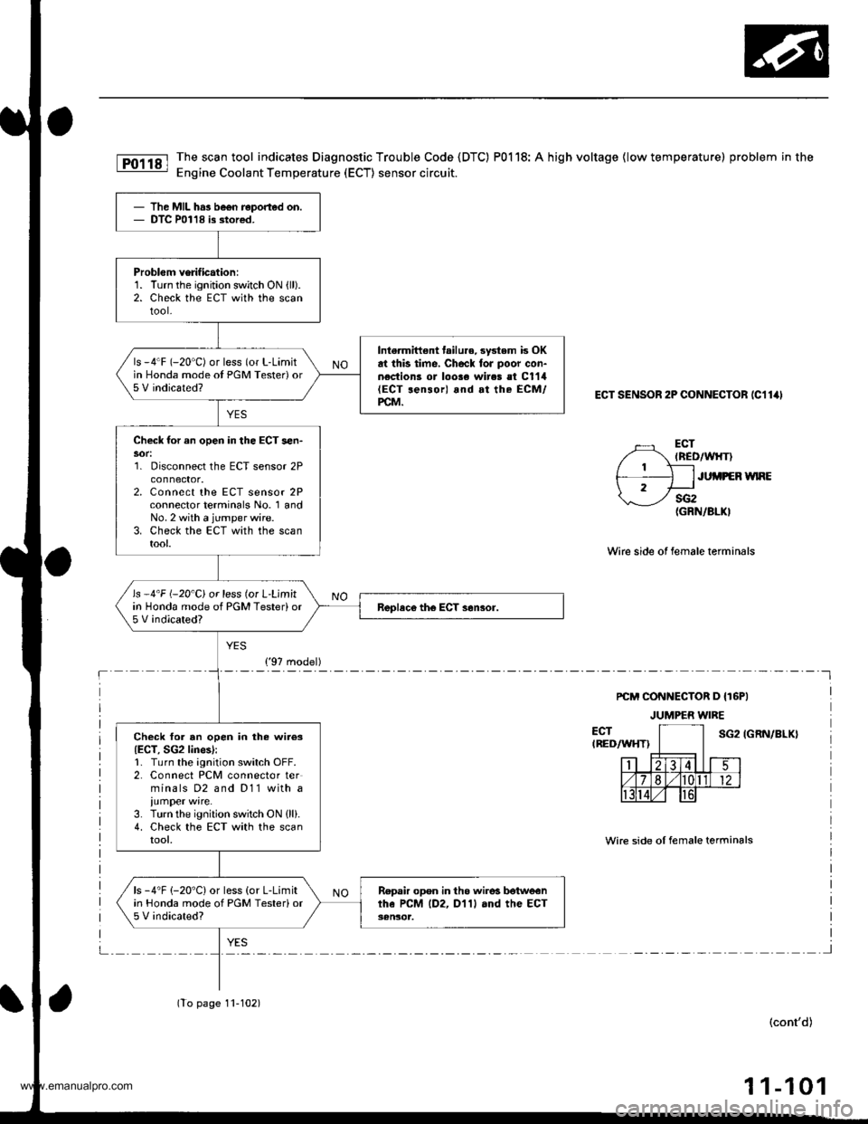
The scan tool indicates Diagnostic Trouble Code {DTC) P0118: A high voltage {low temperature) problem in the
Engine Coolant Temperature (ECT) sensor circuit.
ECT SENSOR 2P CONNECTOB (C11ill
ECT(ncD/wlrT)
ECTIREDAAIHT)
Wirc side of lemale terminals
sG2(GRN/8LKI
PCM CONNECTOR D {T6PI
JUMPER WIRE
JUi,IPEB WNE
IGRN/BLX}
Wire side oI female terminals
(cont'd)
1 1-101
The MIL has be€n reported on.DTC P01'18 is stor€d.
Problem verification:1. Turn the ignition switch ON {ll).2. Check the EcT with the scantool-
Intermiftent tailu.€,3ystem is OKat this time, Checl foJ poor con-n€ction3 or loose wires et C1'14(ECT ren3or) and at the ECM/PCM.
ls -4"F (-20'C) or less (or L-Limitin Honda mode ot PGM Tester) or5 V indicated?
Check for an open in the ECT sen-
1. Disconnect the ECT sensor 2Pconnector.2. Connect the ECT sensor 2Pconnector terminals No. 1 andNo. 2 with a jumper wire.3. Check the ECT with the scantool.
ls -4'F (-20'C) or less (or L'Limitin Honda mode of PGM Tester)or5 V indicated?
Check for an open in the wiies{ECT, SG2 lines):1. Turn the ignition switch OFF.2. Connect PCM connector terminals D2 and D11 with a
iumper wire.3. Turn the ignition switch ON {ll}.4. Check the ECT with the scantool,
ls -4"F (-20'C) or less (or L-Limitin Honda mode of PGM Testerior5 V indicated?
Repair open in th6 wire! botwe€nthe PCM lD2, D'l1l and the ECT3€n30t.
('97 model)
(To page 11-102)
www.emanualpro.com
Page 351 of 1395

ldle Control System
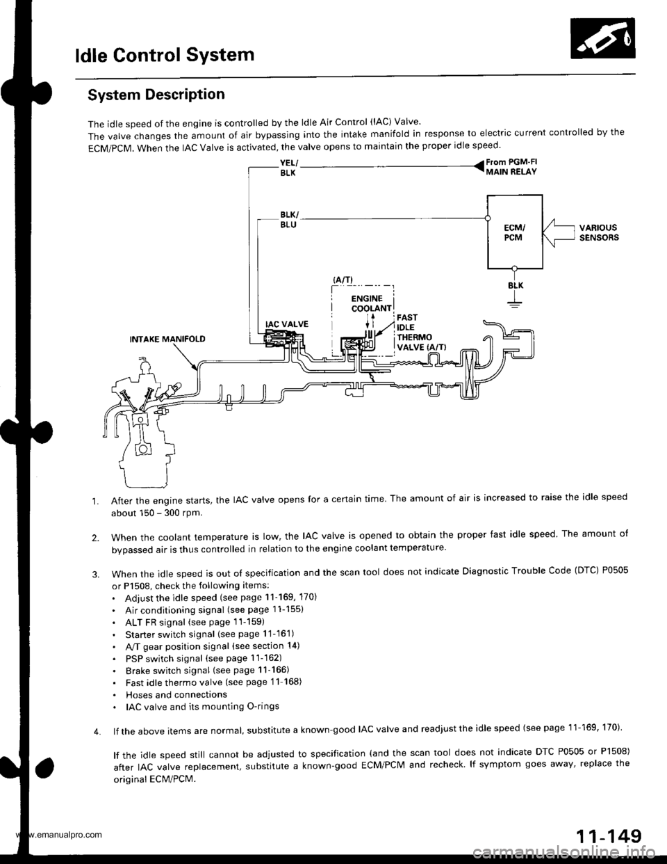
System Description
The idle speed of the engjne is controlled by the ldle Air Control (lAC) Valve'
The valve changes the amount of air bypassing into the intake manifold in response to electric current controlled by the
ECM/PCM. When the lAc valve is activated, the valve opens to maintain the proper idle speed.
YEL/ From PGM'FI
BLK TMAIN RELAY
VARIOUSSENSORS
4.
IAC VALVE
INTAKE MANIFOLD
After the engine starts, the IAC valve opens for a certain time. The amount of air is increased to raise the idle speed
about 150 - 300 rpm.
when the cootant temperature ts row, the lAc valve is opened to obtain the proper fast idle speed The amount o{
bvoassed air is thus controlled in relation to the engine coolant temperature
When the idle speed is out o{ specification and the scan tool does not indicate Diagnostic Trouble Code (DTC) P0505
or P1508, check the following items:
. Adjust the idle speed (see page 11-169, 170)
. Air conditioning signal (seepagell-1551
. ALT FR signal (see page 1l-159)
. Starter switch signal (see page 11-16'1)
. A,/T gear position signal (see section 14)
. PSP switch signal (seepagell-162)
. Brake switch signal (see page 11-165)
. Fast idlethermovalve (see page'11 168)
. Hoses and connecttons. IAC valve and its mounting O-rings
lf the above items are normat, suDslitute a known-good IAC valve and readjust the idle speed {see page 11-169, 170)
lf the idle speed still cannot be adjusted to specification (and the scan tool does not indicate DTC P0505 or Pl508)
after IAC valve reolacement, substitute a known-good ECM/PCM and recheck lf symptom goes away' replace the
original ECM/PCM.
11-149
www.emanualpro.com
Page 352 of 1395

ldle Control System
ldle Control System
I P0505 | The scan tool indicates Diagnostic T.ouble Code (DTCI PO5O5: ldlecontrol svstem mattunction.
NOTE: lf DTC P1508 is stored at the same time as DTC P0505, troubleshoot DTC P1508 first. then troubleshoot DTC p0505.
Possibls Cause
. IAC valve mechanical malfunction. Throttle body clogged port, improper adlustment. Intake manifold gasket leakaging. Intake air hose loose leakaging. Vacuum hose leakaging
a ECT sensor incorrect output. Throttle Position sensor incorrect output
Troubleshooting Flowchart
The MIL has been reDorted on.DTC P0505 is sto.ed.
Problem verificationi1. Start the engine. Hold theengine at 3,000 rpm with noload (in Park or neutral) untilthe radiator Ian comes on, thenlet it idle.2. With the scan tool, check thelollowing items.- Throttle position should beapprox. 10% with the throt-tle {ully closed.- Engine coolant temperature shorJld be 194 - 205'F(90 - 96"C).lf they are not within thespec., repair the faulty sen-sor circuit.3 Check the engine speed atidle with no-load conditions:headlights, blower fan. reardefogger, radiator lan, and airconditioner are not operaling,
Inte.mittent failure. syltem is OKat this time.ls it 750 {730)* i 50 rpm?
ls il 700 (680)' rpm or less?
{To page 11-151)(To page 1'l-151)
l:'99 - 00 models
www.emanualpro.com
Page 353 of 1395
(From page 11-150)
{From page 11-150}
THERMO VALVE(A/T onlyl
Check the IAC valve:Disconnect the 2P connector from
the IAC valve.
Does the engine speed droP
or the engine stall?
Adiust the (basel idl€ speed lseepage 11-169, 1t0). Itihe ba3e idle
speed cannot be adiust€d, clean
the Dorts in the throttle body.
UPPER
Check the tast idle lhermo valve:
1. Turn the ignition switch OFF.
2. Remove the intake air ductfrom the throttle body.3. Start the engine and let it idle.
4. Put your finger on the lowerpon in the throttle body.
Check engine cool.nt level and for
air in the cooling sy3lem. lf OK,
reolace the f.st idle thermo valve.Does the engine speed drop?
Put your Iinger on the uPPer Portin the throttle body.
Check for vacuum leaks, make
sure the throttle valve is com'pletely clo3ed. and repair as nec-Does the engine speed droP?
Adjust the idle spoed lsee Page11-169. 1701. lf the adiustmentdoes not correct lhe problem,
r.olace the IAC valve.
www.emanualpro.com
Page 357 of 1395

Air Conditioning Signal
This signals the EcM/PcM when there is a demand for cooling from the air conditioning system.
'97 modol:
Wire side of lemale terminals
PCM CONNECTOR C (31PI
ACS IBLU/RED)
PCM CONNECTOR A (:TIPI
(cont'd)
1 1-1 55
Chock for a shorl in thc wiro(ACS linol:1. Turn the ignition switch OFF.2. Disconnect the A/C pressure
switch 2Pconneclor.3. Turn the ignition switch ON (ll).,1. [Ieasu re voltage betweenPCM connector terminals C5
and A9.
Check for . .hon in the wire IAGSlinel:1. Turn the ignition switch OFF.2. Disconnect PCM connector C(31P).
3. Check for continuity betweenbody ground and PCM con-nector torminal C5.
Reoaii short in tho wire b€twoenrh6 PCM (Csl and the A/C pres-
3urc 3witch.
- Subcdtrte a known{ood PCMand recheck. lf pr6actibed volt-age is now av{ilable, roplacethe origind PCM,- Soe the eir conditionor in3p€c-lion lsee soction 221.
Check tor an opon in the wite(ACC lino):1. TLrrn the ignition switch OFF.2. Roconnect the A/C pressure
switch 2P connector.3. Turn the ignition switch ON (ll).
4. Momenta rily connect PCMconnector terminals A9 and417 with a iumper wire sev'eraltimes,
Wire side of female terminals
JUMPER WIRE
(To page 11-156)Wire side oI Iemale terminals
www.emanualpro.com
Page 370 of 1395

ldle Control System
Fast ldle Thermo Valve lA/T)
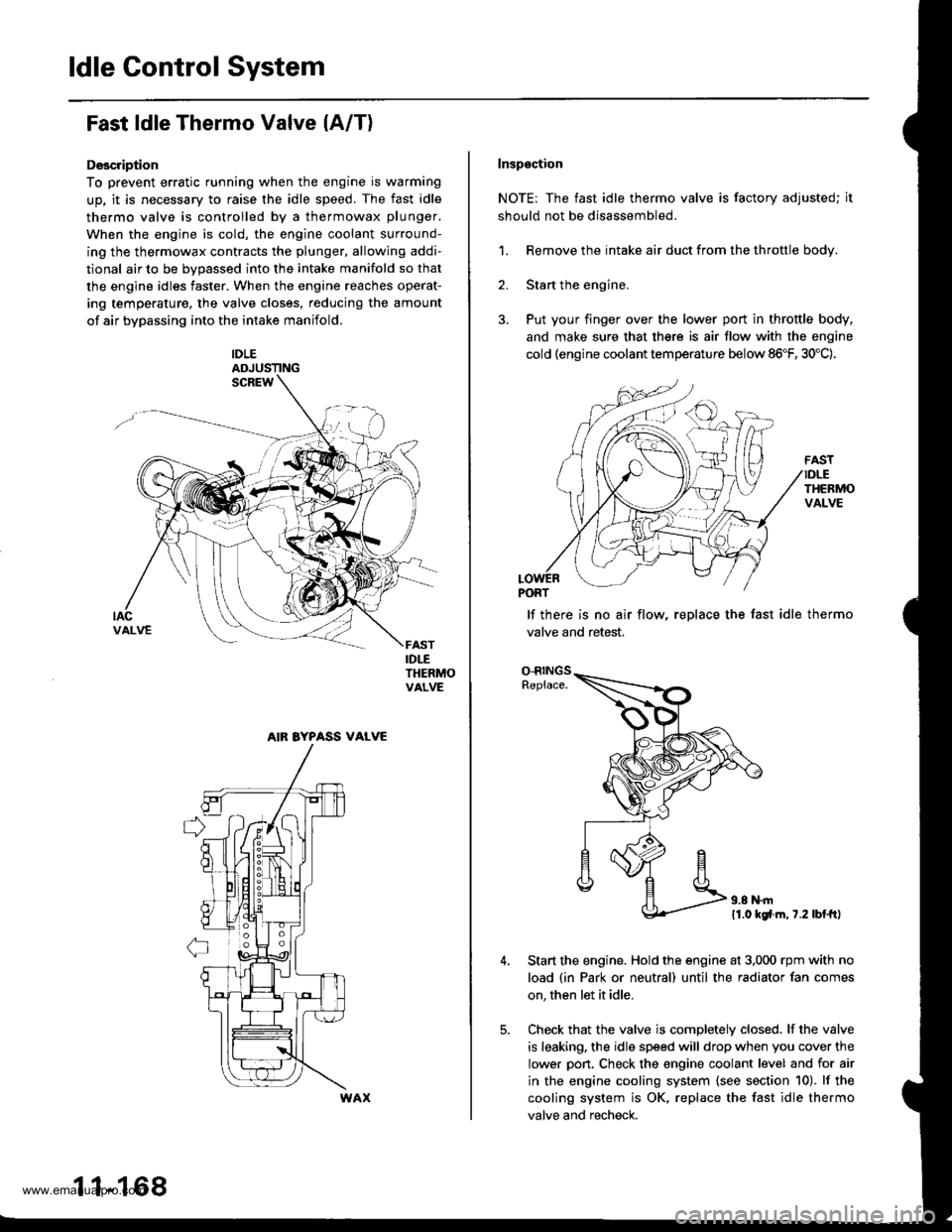
Description
To prevent erratic running when the engine is warming
up, it is necessary to raise the idle speed. The fast idle
thermo valve is controlled by a thermowax plunger.
When the engine is cold, the engine coolant surround-
ing the thermowax contracts the plunger, allowing addi-
tional air to be bvDassed into the intake manifold so that
the engine idles faster. When the engine reaches operat-
ing temperature. the valve closes, reducing the amount
of air bypassing into the intake manifold.
IDLEADJUSTING
IDLETHERMOVALVE
AIR BYPASS VALVE
11-168
Inspgction
NOTE: The fast idle thermo valve is factory adjusted; it
should not be disassembled.
1. Remove the intake air duct from the throttle body.
2. Start the engine,
3. Put your finger over the lower port in throttle body,
and make sure that there is air flow with the engine
cold (engine coolant temperature below 86"F, 30'C).
lf there is no air flow, replace the fast idle thermo
valve and retest,
O-RINGSReplace.
11.0 kgfl.m, 7.2 lbl.ftl
Start the engine. Hold the engine at 3,000 rpm with no
load (in Park or neutral) until the radiator fan comes
on, then let it idle.
Check that the valve is completely closed. lf the valve
is leaking, the idle speed will drop when you cover the
lower pon. Check the engine coolant level and for air
in the engine cooling system {see section 10). lf the
cooling system is OK, replace the fast idle thermo
valve and recheck.
www.emanualpro.com
Page 398 of 1395
Intake Air System
Throttle Body
Doscription
The throttle body is a single-barrel side-draft type. The
lower portion of the throttle valve is heated by engine
coolant from the cylinder head. The idle adjusting screw
which regulates the bypass air is located on the top of
the throttle bodv.
The illustration shows'97 - 98 models,'99 - 00 rnodelsare similar.
1 1-196
lnspection
Check that the throttle cable operates smoothly without
binding or sticking.
lf there are any abnormalities, check for:. Excessive wear or play in the throftle valve shaft.. Sticky or binding throttle lever at the fully closed posi-
tton.
. Clearance between throttle stop screw and throttle
lever at the fully closed position.
97 - 98 models:
THROTTLE LINKAGE
Replace the throttle body if there is excessive play in the
throttle valve shaft or if the shaft is binding or sticking.
THROTTLE LINKAGE
www.emanualpro.com