1999 HONDA CR-V Number parts
[x] Cancel search: Number partsPage 24 of 1395
Service Precautions
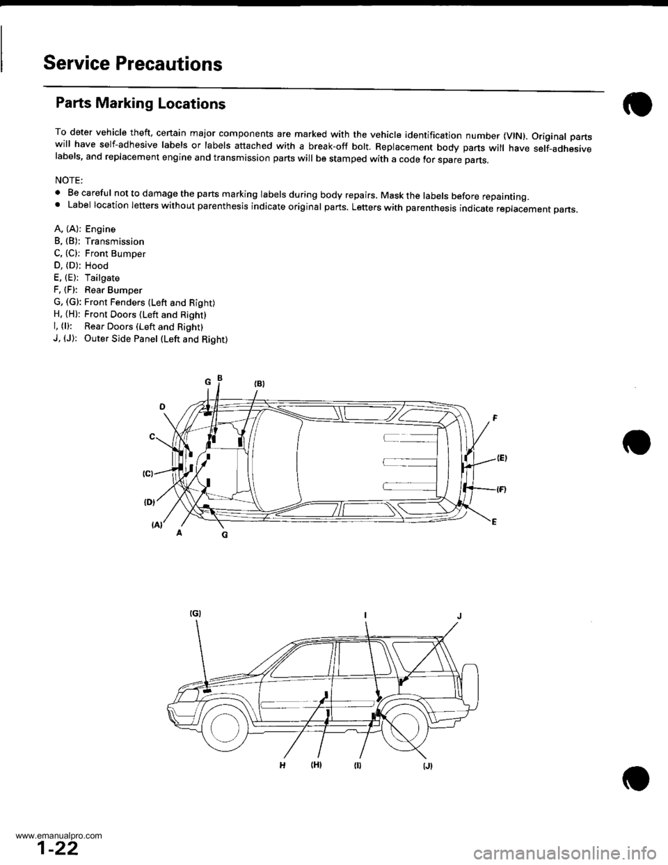
Parts Marking Locations
To deter vehicle theft, cenain major components are marked with the vehicle identification number {VlN). Original partswill have self-adhesive labels or labels attached with a break-off bolt. Replacement body parts will have self-adhesivelabels, and replacement engine and transmission parts will be stamped with a code tor spare parts.
NOTE:
. Be careful nottodamagethe parts marking labelsduring body repairs. Maskthe labels before repainting.' Label location letters without parenthesis indicate original parts. Letters with parenthesis indicate replacement pans.
A, (A): Engine
B, (B): Transmission
C, (C): Front Bumoer
D, (D); Hood
E, (E): Tailgate
F, (F): Rear Bumper
G, (G): Front Fenders (Lefr and Right)H, {H): Front Doors (Left and Right}
l, (l): Rear Doors (Left and Right)
J, (J): Outer Side Panel (Left and Right)
1-22
www.emanualpro.com
Page 169 of 1395
Oil Seals
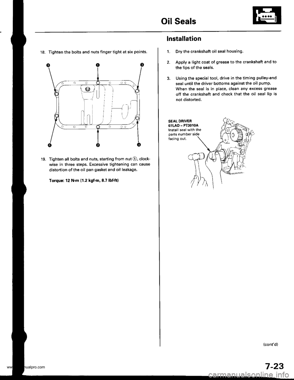
18. Tighten the bolts and nuts finger tight at six points.
Tighten all bolts and nuts, starting from nut O. clock-
wise in three steps. Excessive tightening can cause
distortion ot the oil pan gasket and oil leakage.
Torque: 12 N.m (1.2 kgt.m,8.7 lbtft)
19.
1.
lnstallation
Dry the crankshaft oil seal housing.
Apply a light coat of grease to the crankshsft and to
the lips of the seals.
Using the special tool, drive in the timing pulley-end
seal until the driver bottoms against the oil pump.
When the seal is in place, clean any excess grease
off the crankshaft and check that the oil seal lip is
not distorted,
SEAL DRIVEROTLAD - PT3O1OAlnstall sealwith theparts number sidefacing out.
(cont'd)
7-23
www.emanualpro.com
Page 491 of 1395
Transfer Assembly
Reassembly
Note these items during reassembly:. While reassembling the transfer assembly:- Check and adjust the transfer gear tooth contact.- Measure and adjust the transfer gear backlash.- Check and adjust the tapered roller bearing start-Ing rorque.
. Coat all parts with MTF during reassembly.. Replace the tapered roller bearing and the bearingouter race as a set if either part is replaced.. Replace the transfer drive gear and the transfer dri-ven gear shaft as a set if either part is replaced,
Outline of Assembly
1.Select the 35 mm thrust shim.
Perform this procedure if the transler driven gear
shaft or the tapered roller bearing on the transferdriven gear shaft is replaced.
Preassemble the parts to check and adjust transfergear backlash and transfer gear tooth contact.
Disassemble the parts, then assemble the transferdriven gear shaft and its related parts.
4. Measure and adjust the staning torque of the trans-fer driven gear shaft tapered roller bearing.
5. Assemble the transfer shaft and jts related parts.
6. Measure and adjust the total starting torque.
35 mm Thrust Shim Seleqtion
1. Select the 35 mm thrust shim if the transfer drivengear shaft or the tapered roller bearing on the trans-fer driven gear shaft is replaced.
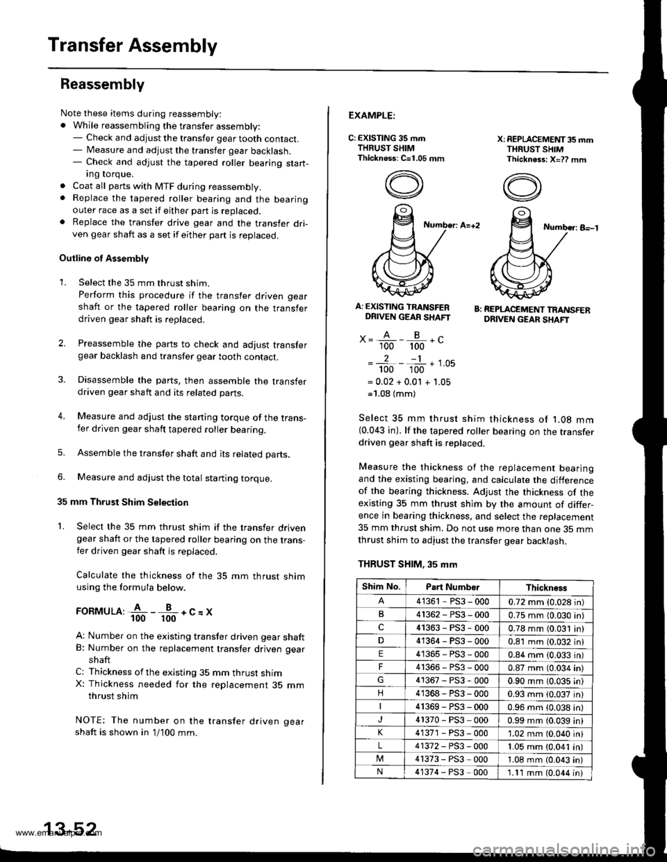
Calculate the thickness of the 35 mm thrust shimusing the formula below.
ronrvruu:fi--fr-+c=x
A: Number on the existing transfer driven gear shaftB: Number on the replacement transfer driven gear
shaft
C: Thickness ofthe existing 35 mm thrust shimX: Thickness needed for the replacement 35 mmthrust shim
NOTE: The number on the transfer driven gear
shaft is shown in 1/100 mm.
2.
3.
13-52
EXAMPLE:
C: EXISTING 35 mmTHRUST SHIMThicknoss: C=1.05 mm
X: REPLACEMET{T35 mmTHRUST SHIMThickness: X=?? mm
Number: A=+2Number: B-l
A: EXISTING TRANSFERDRIVEN GEAR SHAFT
x= A - B -.'- 100 100 -
2-1
100 100 '-
= 0.02 + 0.01 + 1.05-'1.08 (mm)
B: REPLACEMENT TRANSFERDRIVEN GEAF SHAFT
Select 35 mm thrust shim thickness ot '1.08 mm(0.043 in). lf the tapered roller bearing on the transferdriven gear shaft is replaced.
Measure the thickness of the replacement bearingand the existing bearing, and calculate the differenceof the bearing thickness. Adjust the thickness of theexisting 35 mm thrust shim by the amount of differ-ence in bearing thickness. and select the replacement
35 mm thrust shim. Do not use more than one 35 mmthrust shim to adjust the transfer gear backlash,
THRUST SHIM. 35 mm
Shim No.Part NumberThickness
41361 - PS3 - 0000.72 mm (0.028 in)
B41362-PS3-0000.75 mm (0.030 in)
c41363-PS3-0000.78 mm (0.031 in)
41364-PS3-0000.81 mm (0.032 in)
E41365-PS3-0000.84 mm (0.033 in)
F4r366-PS3-0000.87 mm (0.034 in)
41367-PS3-0000.90 mm (0.035 in)
n41368-PS3-0000.93 mm (0.037 in)
41369-PS3-0000.96 mm {0.038 in)
41370-PS3-0000.99 mm (0.039 in)
41371 - PS3 - 0001.02 mm (0.040 in)
L41372-PS3-0001.05 mm (0.041 in)
41373-PS3-0001.08 mm (0.043 in)
N41374-PS3-0001.11 mm (0.044 in)
www.emanualpro.com
Page 720 of 1395
MainshaftSealing Rings
Inspection (cont'dl
It the clearance is out of standard, remove the
thrust washer and measure its thickness.
Select and install a new washer, then recheck the
clearance, and make sure it is within standard.
THRUST WASHER 36.5 x 55 mm
No.Part NumberThickness
190441 - PG4,0104.00 mm (0.157 in)
290442-PG4-0104.05 mm (0.159 in)
90443-PG4-0104.10 mm {0.161 in)
90444-PG4-0104.15 mm {0.163 in)
90445-PG4-0104.20 mm (0.'165 in)
690446-PG4-0104.25 mm {0.167 in)
190447-PG4-0104.30 mm (0.169 in)
890448-PG4-0104.35 mm (0.171 in)
I90449-PG4-0104.40 mm (0.173 in)
1090450-PG4-0004.45 mm (0.175 inl
14-204
Replacement
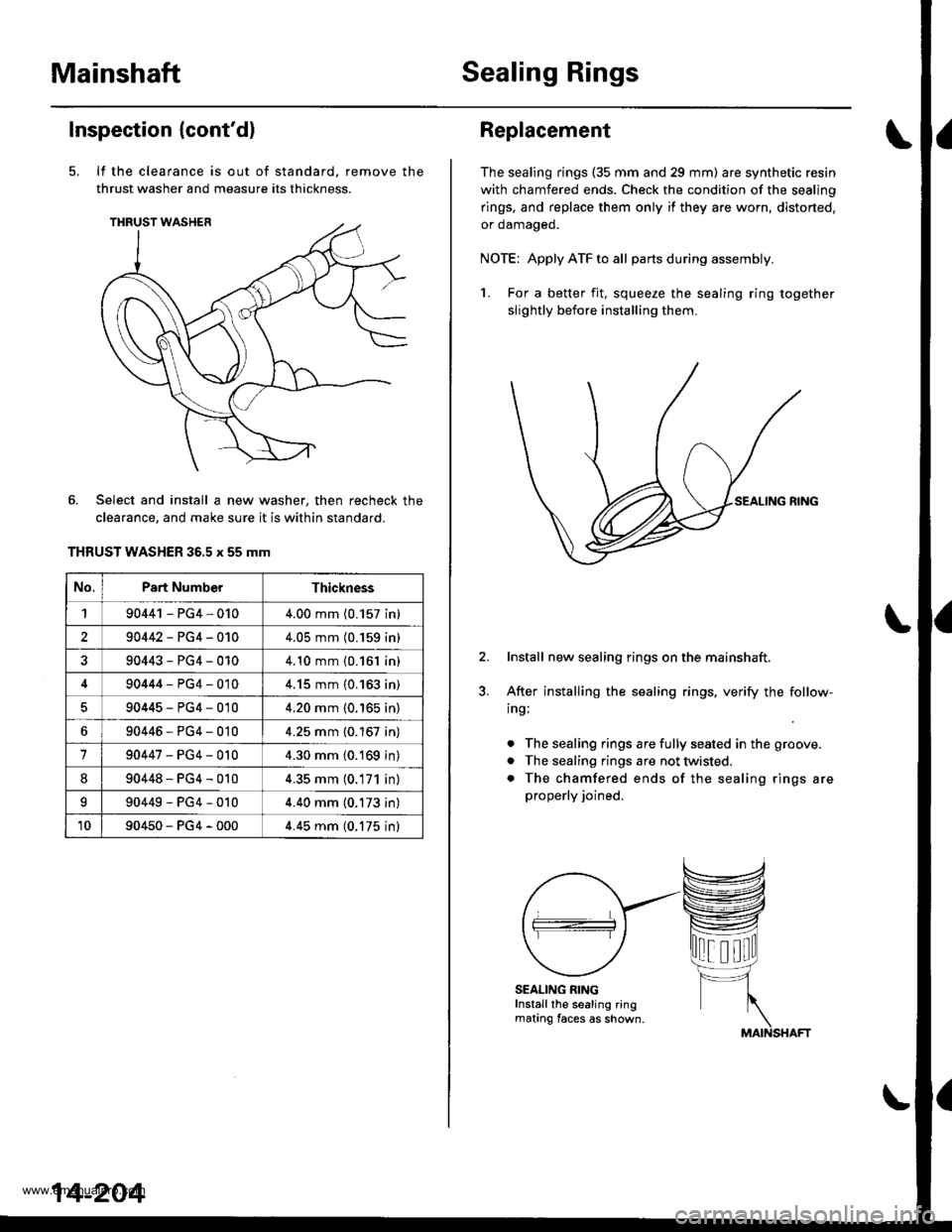
The sealing rings (35 mm and 29 mm) are synthetic resin
with chamfered ends. Check the condition of the sealing
rings, and replace them only if they are worn, distorted,
or oamageo.
NOTE: Apply ATF to all partsduring assembly.
1. For a better fit, squeeze the sealing ring together
slightly before installing them.
Install new sealing rings on the mainshaft.
After installing the sealing rings, verify the follow-
ing:
. The sealing rings are fully seated in the groove.
. The sealing rings are not twisted.
. The chamfered ends of the sealing rings are
properly joined.
SEALING RINGInstall the sealing ringmating faces as shown.
www.emanualpro.com
Page 724 of 1395
Countershaft
Inspection (cont'd)
3.
4.
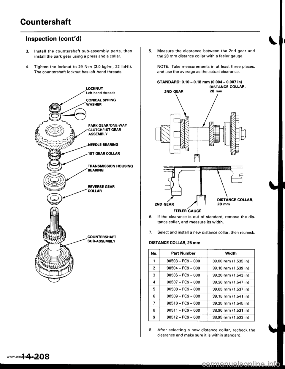
Install the countershaft sub-assembly parts, then
installthe park gear using a press and a collar.
Tighten the locknut to 29 N.m (3.0 kgf.m, 22 lbf.ft).
The countershaft locknut has left-hand threads.
LOCKNUTLe{t-hand threads
CONICAL SPRINGWASHER
PABK GEAR/ONE.WAYCLUTCH/1ST GEARASSEMBLY
NEEDLE BEANING
lST GEAR COLLAR
TRANSMISSION HOUSINGAEARING
REVERSE GEARCOLLAR
COUNTERSHAFTSUB.ASSEMBLY
14-208
5. Measure the clearance between the 2nd gear and
the 28 mm distance collar with a feeler gauge.
NOTE: Take measurements in at least three places,
and use the average as the actual clearance.
STANDARD: 0.10 - 0.18 mm (0.004 - 0.007 in)
OISTANCE COLLAR,28 mm
FEELER GAUGE
6. lf the clearance is out ot standard, remove the dis-
tance collar, and measure its width.
7. Select and install a new distance collar, then recheck.
DISTANCE COLLAR,28 mm
8. After selecting a new distance collar. recheck the
clearance and make sure it is within standard.
2NO GEAR
No.Part Numberwidrh
190503-PCg-00039.00 mm ('1.535 in)
290504-PCg-00039.'10 mm (1.539 in)
?90505-PCg-00039.20 mm {1.543 in)
90507-PCg-00039.30 mm (l.547 in)
90508*PCg-00039.05 mm (l.537 in)
90509-PCg-00039.15 mm (l.541 in)
790510-PCg-00039.25 mm {1.545 in)
890511-PCg-00038.90 mm { L531 in)
990512-PCg-00038.95 mm ( 1.533 in)
www.emanualpro.com
Page 756 of 1395
Transfer Assembly
Reassembly
NOTE:
. While reassembling the transfer assembly:. Check and adjust the transfer gear tooth contact.. Measure and adjust the transfer gear backlash.. Check and adjust the tapered roller bearing stan-
ing torque.
. Coat all pans with ATF during reassembly.. Replace the tapered roller bearing and the bearing
outer race as a set if either part is replaced.. Replace the transfer drive gear and the transfer dri-ven gear shaft as a set if either part is replaced.
Outline of Assembly
1.Select the 35 mm thrusi shim.
Psrtorm this procedute if the transter driven g€ar
shaft or the tapered roller bearing on the transfer
driven gear shaft is replaced.
Prea$emble the parts to check and adiust transtelgear backlash and transfer gear tooth contact.
Disassemble the parts, then assemble the translerdriven gsar shaft and its related pans.
2.
3.
4. Measure and adjust the starting torque oI the
transfer driven gear shaft tapered roller bearing.
5. Assemble the transfer shaft and its related parts.
6. Measure and adiust the total starting torque.
35 mm Thrust Shim Selection
L Select the 35 mm thrust shim if the transfer drivengear shaft or the tapered roller bearing on the trans-
fer driven gear shaft is replaced.
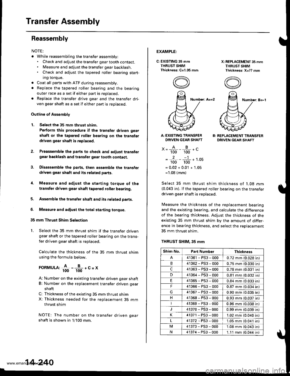
Calculate the thickness of the 35 mm thrust shimusing the formula below.
FoRMULA:+ -*-+c=x
A: Number on the existing transfer driven gear shaft
B; Number on the replacement transfer driven gear
shaft
C: Thickness ofthe existing 35 mm thrust shimX: Thickness needed for the replacement 35 mmthrust shim
NOTE: The number on the transfer driven oear
shaft is shown in 'll100 mm.
14-240
EXAMPLE:
C: EXISTING 35 mmTHRUST SHIMThickness: C=1.05 mm
X: REPLACEMENT 35 mmTHRUST SHIMThickness: X=?? mm
Number: A=+2Numbe.: B=-'l
Ar EXISTING TRANSFERDRIVEN GEAR SHAFT
x= A - B .c" 100 100 -
2-1
100 100 '-
= 0.02 + 0.0'l + 1.05=1.08 {mm)
B: REPLACEMENT TRANSFERDRIVEN GEAR SHAFT
Select 35 mm thrust shim thickness of l�08 mm(0.043 in). lf the tapered roller bearing on the transfer
driven gear shaft is replaced.
Measure the thickness of the replacement bearingand the existing bearing, and calculate the difference
of the bearjng thickness. Adjust the thickness of the
existing 35 mm thrust shim by the amount of differ-
ence in bearing thickness, and select the replacement
35 mm thrust shim.
THRUST SHIM, 35 mm
Shim No.Part NumberThickness
41361 - PS3 - 0000.72 mm (0.028 in)
41362-PS3-0000.75 mm {0.030 in}
c41363-PS3-0000.78 mm (0.03'1 in)
D41364-PS3-0000.81 mm (0.032 in)
41365-PS3-0000.84 mm (0.033 an)
F41366-PS3-0000.87 mm (0.034 in)
41367-PS3-0000.90 mm (0.035 in)
H41368-PS3-0000.93 mm (0.037 in)
41369-PS3-0000.96 mm 10.038 in)
41370-PS3-0000.99 mm (0.039 in)
K4 r371 - PS3 - 0001.02 mm (0.040 in
41372-PS3-0001.05 mm (0.041 in
M41373-PS3-0001.08 mm (0.043 in
N41374-PS3-000'1.11 mm 10.044 in
www.emanualpro.com
Page 1316 of 1395
Precautions/Procedures
)General Precautions
Carefully inspect any SRS part before you install it.
Do not install any part that shows signs of being drop-
ped or improperly handled, such as dents, cracks or
deformation:
- Airbags- Cable reel- SRS unit- Seat belt tensioners
N
)-
Use only a digital multimeter to check the system, lf
it's not a Honda multimeter, make sure its output is
10 mA (0,01 A) or less when switched to the smallest
value in the ohmmeter range. A tester with a higher
output could damage the airbag circuit or cause acci-
dental deployment and possible injury.
Do not install used SRS Dans from another vehicle,
When making SRS repairs, use only new pans.
Except when performing electrical inspections,
always disconnect both the negative cable and posi-
tive cable from the batterv. and wait at least three
minutes before beginning work.
Replacement of the combination light and wiper/
washer switches and cruise control switch can be
done without removing the steering wheel:
- Combination light and wiper/washer switch replace-
ment {see section 231.- Cruise control sevresume switch replacement (see
section 41.
Whenever the ignition switch is ON {ll}, or has been
turned OFF for less than three minutes, be careful not
to bump the SRS unit; the airbags could accidentally
deploy and cause damage or injuries.
Whenever the airbag has been activated, replace the
SRS unit.
The original radio has a coded theft protection circuit.
Be sure to get the customer's code number before dis-
connecting the battery cables.
)
Airbag/Seat Belt Tensioner
Handling and Storage
Do not try to disassemble an airbag or a seat belt ten-
sioner. They have no serviceable parts. Once an airbag
or a seat belt tensioner have been deployed. they cannot
be repaired or reused.
For temporary storage of an airbag or a seat belt ten-
sioner during service, please observe the following pre-
cautons:
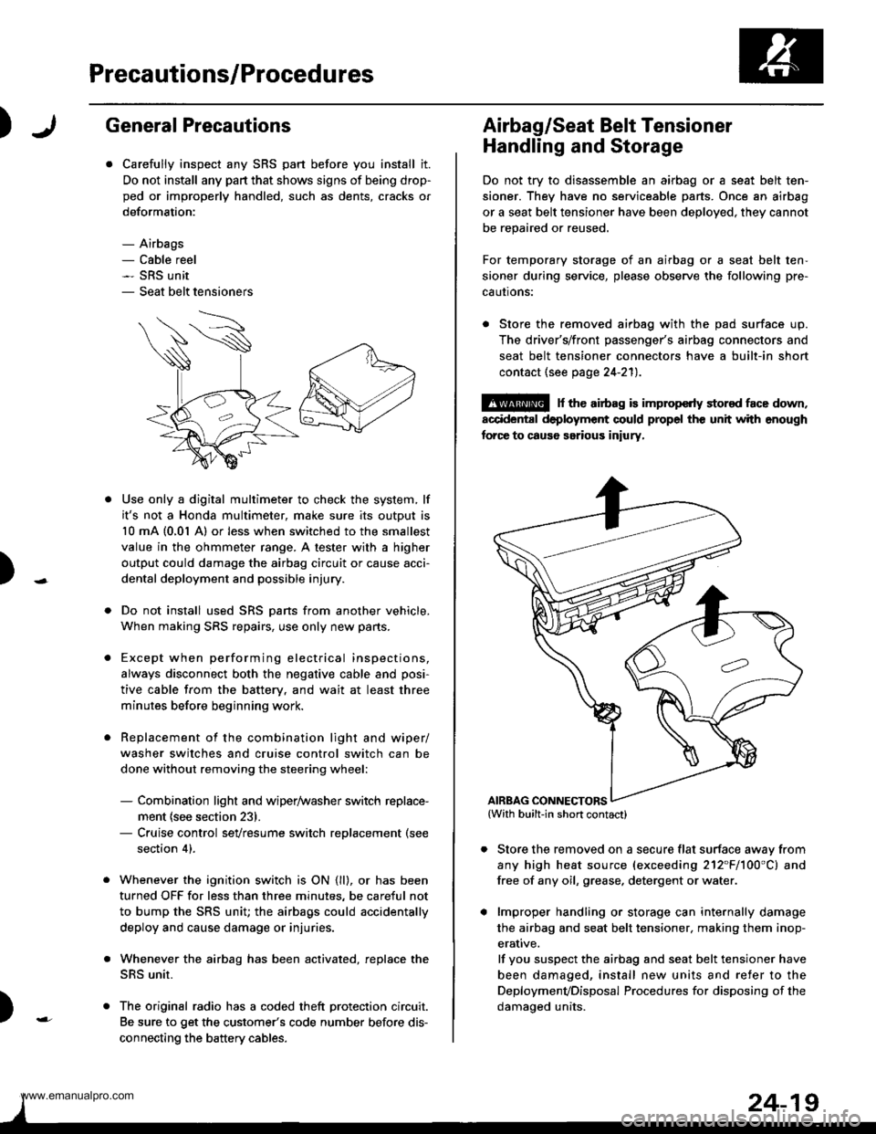
. Store the removed airbag with the pad surface up.
The driver's/front passenger's airbag connectors and
seat belt tensioner connectors have a built-in short
contact (see page 24-211.
@ r th€ airb.g is impropcrty stor€d face down,
accidental deployment could propel the unit with enough
forc€ to caus6 serious iniury,
Store the removed on a secure flat surface awav from
any high heat source (exceeding 212"F/100'C) and
free of any oil, grease. detergent or water.
lmproper handling or storage can internally damage
the airbag and seat belt tensioner. making them inop-
erative.
lf you suspect the airbag and seat belt tensioner have
been damaged, install new units and refer to the
Deploymenvoisposal Procedures for disposing of the
damaoed units.
AIRBAG CONNECTORS
www.emanualpro.com