Page 475 of 1395
Synchro Sleeve, Synchro Hub
Inspection
1.Inspect gear teeth on all synchro hubs and synchro
sleeves for rounded off corners, which indicate
Install each synchro hub in its mating synchro
sleeve, and check for freedom of movement.
NOTE: lf replacement is required, always replace
the synchro sleeve and synchro hub as a set.
SYNCHROSLEEVE
SYNCHBOHUB
13-36
LONGER ?EETH
Installation
When assembling the synchro sleeve and synchro hub,
be sure to match the three sets of longer teeth ('120
degrees apart) on the synchro sleeve with the three sets
of deeper grooves in the synchro hub. Do not installthe
synchro sleeve with its longer teeth in the lsv2nd syn-
chro hub slots because it will damage the spring ring.
SYNCHRO
SYNCHBOSI.EEVE
www.emanualpro.com
Page 476 of 1395

Synchro Ring, Gear
Inspection
Inspect the synchro ring and gear.
Ar lnspect the inside of the synchro ring for wear.
B: lnspect the synchro sleeve teeth and matching
teeth on the synchro ring for wear (rounded of0.
CCGOOO WORN
Cr Inspect the synchro sleeve teeth and matching
teeth on the gear tor wear (rounded off).
,,
u (-l
GOOO WORN
D: Inspect the gear hub thrust surface for wear.
E: Inspect the cone surface lor wear and roughness.
F: Inspect the teeth on all gears for uneven wear,
scoring, galling, and cracks.
2. Coat the cone surface of the gear with oil, and place
the synchro ring on the matching gear. Rotate the
synchro ring, making sure that it does not slip.
Measure the clearance between the synchro ring
and gear allthe way around.
NOTE: Hold the synchro ring against the gear even-
ly while measuring the clearance.
Synchro Ring-to-Gear Clearance
Standard: 0.85 - 1.10 mm (0.033 - 0.0,lil in)
Service Limit: 0.,1 mm 10.02 inl
Double Cone Synchro-lo-Goar Clearance
Standard:
@: {Outer Synchro Ring to Synchto Conel
0.5 - 1.0 mm (0.02 - 0.04 in)
€): {synchro cone to Geal)
0.5 - 1.0 mm (0.02 - 0.0i1inl
@: louter Synchro Ring to Gearl
0.95 - 1.68 mm (0.037 - 0.056 inl
Service Limit:
@: 0.3 mm (0.01 inl
@: 0.3 mm {0.01 in}
@: 0.6 mm {0.02 in)
lf the clearance is less than the service limit, replace
the synchro ring and synchro cone.
SYNCHRO SPRING
SYNCHRO
1.
OUTER SYNCHRO RING
13-37
www.emanualpro.com
Page 477 of 1395

Differential
lndex
NOTE: lf the * mark parts were replaced, the tapered
roller bearing preload must be adjusted (see page 13-
41).
*THRUST SHIMAdiustment, Page 13'41
+BEARING OUTER RACEBeplacement, page 13 40Inspect for wear and damage.
*TAPERED ROLLERBEARINGReplacement, page l3-39Inspect for wear and damage.
10 x 1.0 mm103 N.m {10.5 kgf m, 75.9 lbf.ft}Left-hand threads
CARRIERBacklash inspection, page 13 38lnspect for cracks.
FINAL DRIVEN GEARReplacement, page 13-39Inspect for wear and damage
TRANSFER DRIVEN GEARReplacement, page 13-39Inspect {or wear and damage.
,,4\
W-
*TAPERED ROLLER BEARINGBeplacement, page 13'39Inspect for wear and damage.
IEEARING OUTER RACEReplacement, page 13-40Inspect for wear and damage.
.75 mm SHIM
13-38
Backlash Inspection
1. Place the differential
install both axles.
assembly on V-blocks and
PINION GEARS
V-BLOCK
2. Measure the backlash ot both pinion gears.
Standard (Newl: 0.05 - 0.15 mm (0.002 - 0.006 inl
lf the backlash is not within the standard, reolace
the differential carrier.
www.emanualpro.com
Page 478 of 1395

Final Driven Gear RePlacement
LRemove the bolts in a crisscross pattern in several
steps, and remove the final driven gear from the dif-
ferential carrier.
NOTE: The final driven gear bolts have left-hand
threads.
10 x 1.0 mm103 N.m (10.5 kgf m,75.9lbf'ftlLeft'hand threads
FINAL DRIVEN GEAR
lnsoect {or weal and damage
TRANSFER ORIVEN GEARInspect for wear and damage.
Install the final driven gear by tightening the bolts
in a crisscross pattern in several steps.
Tapered Roller Bearing
Replacement
Note these items:
. The tapered roller bearing and bearing outer race
should be replaced as a set.
. Inspect and adiust the tapered roller bearing preload
whenever the tapered roller bearing is replaced'
. Check the tapered roller bearings for wear and rough
rotation. lf the tapered roller bearings are OK, remov-
al is not necessary.
1. Remove the tapered roller bearings using a bearing
puller and a bearing separator as shown.
Install new tapered roller bearings using the special
tool as shown.
NOTE: Drive the tapered roller bearings on until
they bottom against the differential carrter.
PRESS
IJ
BEARINGSEPAFATOB{Commercially
ATTACHMENT,,10 x 50 mm07LAD - PWs060 l
BEARING
13-39
www.emanualpro.com
Page 479 of 1395

Differential
Bearing Outer Race Replacement
Note these items:
. The bearing outer race and tapered roller bearingshould be replaced as a set.. lnspect and adjust the tapered roller bearing preload
whenever the tapered roller bearing is replaced.
'1. Remove the oil seals from the transmission housingand clutch housing (see page j3-43).
2. Drive the bearing outer race and thrust shim out ofthe transmission housing, or remove the bearingouter race and 75 mm shim from the clutch housingby heating the clutch housing to about 212"F(100"C) with a heat gun. Do not reuse the thrustshim if the outer race was driven out.
TRANSMISSIONHOUSING:
ATTACHMENT52x55mm07746 - 0010400
THRUST SHIM
BEARINGOUTER RACE
CLUTCHHOUSING:
13-40
4, lnstallthe oil seal (see page 13-43).
3. Install the thrust shim or 75 mm shim and the bear-ing outer race in the transmission housing andclutch housing using the special tools.
Note these items during bearing replacement:. Install the bearing outer race squarely.. Check that there is no clearance between thebearing outer race, thrust shim or 75 mm shimand housing.
TRANSMISSIONHOUSING:
HANDI-E07749 - 00 xxto
ATTACHMENT,62x68mm077ir6 - 0010500
BEARINGOUIER RACETHRUST SHIM
CLUTCHHOUSING:HANDLE07749 - 001tXX)o
ATTACHMENT.72xt5mm07745 - 00106{x)
OUTER RACE
75 mm SHIM
www.emanualpro.com
Page 480 of 1395

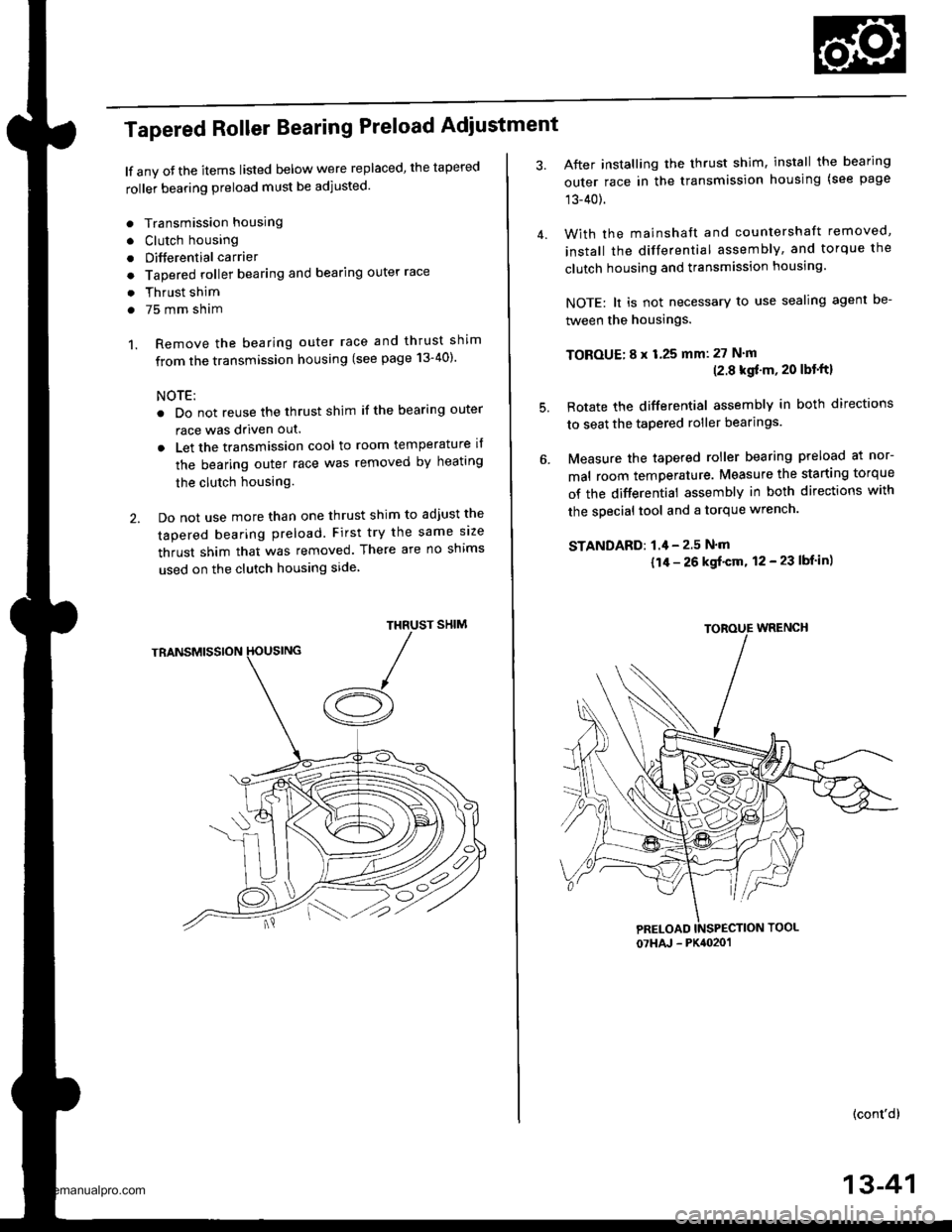
Tapered Roller Bearing Preload Adiustment
lf any oJ the items listed below were replaced, the tapered
roller bearing preload must be adjusted.
. Transmission housing
. Clutch housing
. Differential carrier
o Tapered roller bearing and bearing outer race
. Thrust shim
. 75 mm sham
1. Remove the bearing outer race and thrust shim
from the transmission housing (see page 13-40)'
NOTE:
. Do not reuse the thrust shim if the bearing outer
race was driven out.
. Let the transmission cool to room temperature il
the bearing outer race was removed by heating
the clutch housing.
2. Do not use more than one thrust shim to adjust the
tapered bearing preload. First try the same size
thrust shim that was removed. There are no shims
used on the clutch housing side
SHIMTHRUST
/A
After installing the thrust shim, install the bearing
outer race in the transmission housing (see page
13-40).
With the mainshaft and countershaft removed,
install the differential assembly, and torque the
clutch housing and transmission housing.
NOTE: lt is not necessary to use sealing agent be-
tween the housings.
TOBOUE; 8 x 1.25 mm: 27 N'm(2.8 kgf'm, 20 lbt'ftl
Rotate the differential assembly in both directions
to seat the tapered roller bearings.
Measure the tapered roller bearing preload at nor-
mal room temperature. Measure the starting torque
of the differential assembly in both directions with
the special tool and a torque wrench.
STANDAFD: 1.4 - 2.5 N'm
{1/r - 26 kgf'cm, 12 - 23 lbf in)
(cont'd)
4.
5.
07HAJ - PK4020'�1
13-41
www.emanualpro.com
Page 481 of 1395

Differential
Tapered Roller Bearing Preload Adjustment (cont'd)
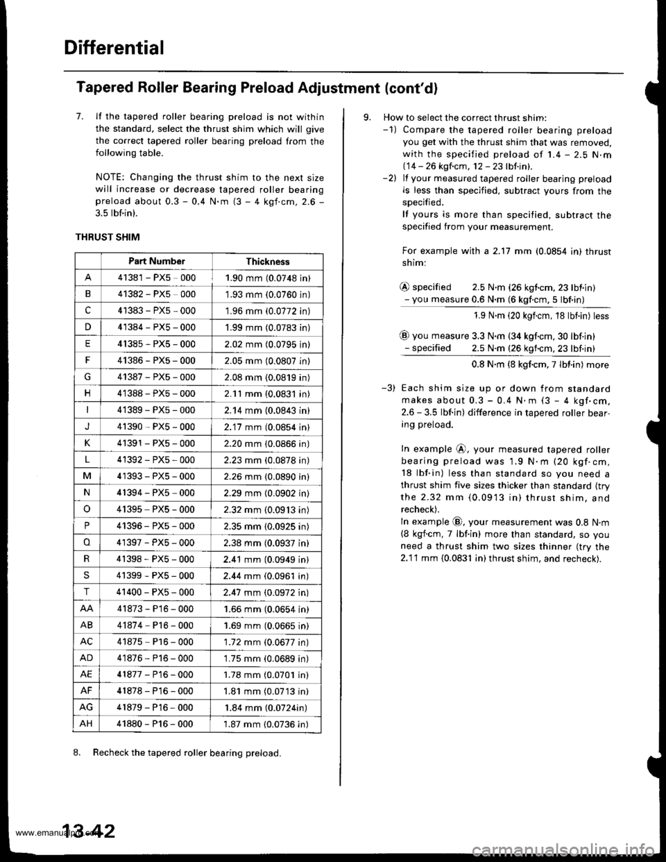
7. lf the tapered roller bearing preload is not within
the standard, select the thrust shim which will give
the correct tapered roller bearing preload from the
following table.
NOTE: Changing the thrust shim to the nexl size
will increase or decrease tapered roller bearingpreload about 0.3 - 0.4 N.m (3 - 4 kgf.cm, 2.6 -
3.5 lbf.in).
THRUST SHIM
8. Recheck the tapered roller bearing preload.
Part Numbe.Thickness
41381 - PX5 0001.90 mm (0.0748 in)
B41382 - PX5 0001.93 mm {0.0760 in)
c41383-PX5-000'1.96 mm (0.0772 in)
n41384-PX5-0001.99 mm (0.0783 in)
E41385-PX5-0002.02 mm (0.0795 in)
F41386-PXs-0002.05 mm (0.0807 in)
G41387-PXs-0002.08 mm (0.0819 in)
n41388-PX5-0002.11 mm (0.0831 in)
41389-PX5-0002.14 mm (0.0843 in)
J41390-PXs-0002.'17 mm (0,0854 in)
K41391 - PX5 - 0002.20 mm (0.0866 in)
4'1392-PX5-0002.23 mm (0.0878 in)
M41393-PX5-0002.26 mm (0.0890 in)
N41394-PX5-0002.29 mm (0.0902 in)
o41395, PXs - 0002.32 mm (0.09'13 in)
P41396-PX5-0002.35 mm (0.0925 in)
o41397-PX5-0002.38 mm (0.0937 in)
4'�t398-PXs-0002.41 mm (0.0949 in)
S41399-PXs-0002.44 mm (0.0961 in)
T41400-PXs-0002.47 mm (0.0972 in)
41873-P16-0001.66 mm (0.0654 in)
AB41874-Pl6-0001.69 mm (0,0665 in)
AC41875 P16 - 000'1.72 mm (0.0677 in)
AD41876-P16-0001.75 mm (0.0689 in)
AE41877-P16-0001.78 mm (0.0701 in)
AF41878-P16-0001.81 mm (0.07'13 in)
41879-P16-000'1.84 mm (0.0724in)
AH41880-P16-0001.87 mm {0.0736 in)
13-42
9. How to select the correct thrust shim:-1) Compare the tapered roller bearing preload
you get with the thrust shim that was removed,
with the specified preload of 1.4 - 2.5 N.m(14 -- 26 kgfcm, 12-23lbtinl.-2) lf your measured tapered roller bearing preload
is less than specified. subtract yours from the
specified,
lf yours is more than specified, subtract the
specified from your measurement.
For example with a 2.17 mm (0.0854 in) thrust
shiml
@ specified 2.5 N.m (26 kgf.cm,23 lbiin)- you measure 0.6 N.m (6 kgf.cm,5 lbf.in)
1.9 N.m (20 kgicm, 18 tbt.in) tess
@ you measure 3.3 N.m (34 kgf.cm,30 lbf.in)- specified 2.5 N.m (26 kgncm,23 lbf.in)
0.8 N.m (8 kgf.cm,7lbt.in) more
Each shim size up or down from standard
makes about 0.3 - 0.4 N.. (3 - 4 kgf'cm,
2.6 - 3.5 lbf.in) difference in tapered roller bear-
ing preload.
In example @, your measured tapered roller
bearing preload was 1.9 N.m (20 kgf.cm,
18 lbf.in) less than standard so you need a
thrust shim five sizes thicker than standard {trythe 2.32 mm (0.0913 in) thrusr shim. and
recheck).
ln example @, your measurement was 0,8 N.m
{8 kgf.cm, 7 lbf.in) more than standard, so you
need a thrust shim two sizes thinner (try the
2.1'l mm {0.0831 in) thrust shim, and recheck).
www.emanualpro.com
Page 482 of 1395
Oil Seal Replacement
Transmission Housing:
1. Remove the oil seal from the transmission housing
2.lnstall the new oil seal into the transmission hous-
ing using the special tools.
NOTE: Install oil seal up to i0.5 mm (10.02 jn) from
transmission housing end surface.
TRANSMISSIONHOUSING
PRESS
fHANOLE
.--.'/'01119 - @1OCIO0
DRIVER ATTACHMENT- PG4()r00
PILOT,28 x 30 mm07JAO - PH80400
OIL SEALReplace.
OIL SEAL
Clutch Housing:
1. Remove the oil seal from the clutch housing.
HANDLE
lnstall the new oil seal into the clutch housing using
the special tools.
NOTE: Install oil seal up to t0.5 mm (t0.02 in) from
transmission housing end surface
CLUTCHHOUSING
PRESS
I
07749 - tx)l(xxto
DRIVER ATTACHMENTOTJAD - PHM1Ol
PILOT, 28 x 30 mm07JAD - PH8oaU)
Replace.
13-43
www.emanualpro.com