Page 484 of 1395

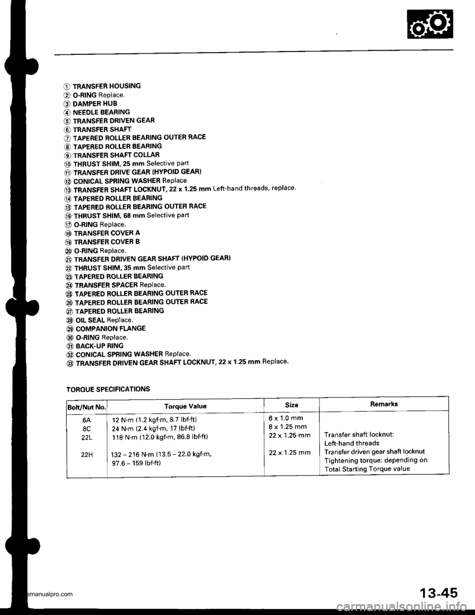
O TRANSFER HOUSING
@ O-RING Replace.
O DAMPER HUB
G) NEEDLE BEARING
G) TRANSFER DRIVEN GEAR
G) TRANSFER SHAFT
O TAPERED ROLLER BEARING OUTER RACE
@ TAPERED ROLLER BEARING
€) TRANSFER SHAFT COLLAR
@ THRUST SHIM, 25 mm selective part
6D TRANSFER DRIVE GEAR (HYPOID GEAR)
@ CONICAL SPRING WASHER RePlace
GD TRANSFER SHAFT LOCKNUT.22 x 1.25 mm Left-hand threads, replace'
E) TAPERED ROLLER BEARING
@ TAPERED ROLLER BEARING OUTER RACE
@ THRUST sHlM. 68 mm selective part
O o.RlNG Replace.
@ TRANSFER COVER A
GD TRANSFER COVER B
@ O-RING Replace.
€) TRANSFER DRIVEN GEAR SHAFT (HYPOID GEAR}
@ THRUST SHIM, 35 mm Selective Part
@ TAPERED ROLLER BEARING
@ TRANSFEB SPACEB RepIace.
@ TAPERED ROLLER BEARING OUTER RACE
@ TAPERED ROLLER BEARING OUTER RACE
@) TAPERED ROLLER BEARING
@ olL SEAL Replace.
@ COMPANION FLANGE
@ O-RING Replace.
@ BACK-UP RING
@ coNtcAL SPRING WASHEB Replace.
(o TRANSFER DRIVEN GEAR SHAFT LOCKNUT,22 x 1.25 mm Replace.
TOROUE SPECIFICATIONS
Boh/Nut No.Torque ValueSizeRemarks
6A
8C
22L
22H
12 N.m (1.2 kgf.m.8.7 lbf.ft)
24 N.m {2.4 kgf.m, 17 lbf'ft)
118 N.m (12.0 kgf.m, 86.8 lbf'ftl
132 - 216 N.m (13.5 - 22.0 kgf'm,
97.6 - 159 lbf.ft)
6x1.0mm
8 x 1.25 mm
22 x 1 ,25 mm
22 x 1 .25 mm
Transfer shaft locknut:
Lett-hand threads
Transfer driven gear shaft locknut
Tightening torque: dePending on
Total Starting Torque vaiue
13-45
www.emanualpro.com
Page 485 of 1395

Transfer Assembly
Inspection
NOTE: To prevent damage to the transfer housing,
always use soft jaws or equivalent materials between
the transfer housing and the vise.
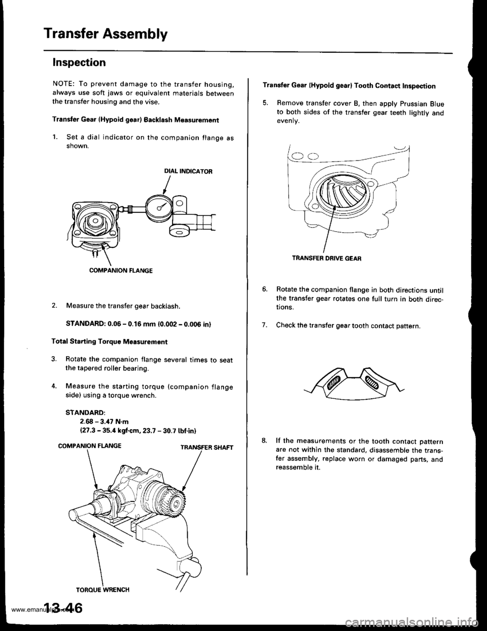
Transter Gaar (Hypoid goar) Backlssh M€asurement
1. Set a dial indicator on the companion flange asshown.
2. Measure the transfer gear backlash.
STANDARD: 0.06 - 0.16 mm {0.002 - 0.006 in}
Total Sta.ting Torquo Msasuremont
3. Rotate the companion flange several times to seatthe tapered roller bearing.
4. Measure the starting torque (companion flange
side) using a torque wrench.
STANDARD:
2.68 - 3.47 N.m
{27.3 - 35.4 kgf.cm.23.7 - 30.7 tbt.in)
DIAL INDICATOR
COMPANION FLANGE
13-46
Transfer Gear lHypoid gearl Tooth Contaqt Insp€ction
5. Remove transfer cover B, then apply Prussian Blueto both sides of the transler gear teeth lightly andevenlv.
Rotate the companion flange in both directions untilthe transfer gear rotates one full tuln in both direc-tions.
Check the transfer gear tooth contact pattern.7.
lf the measurements or the tooth contact Datternare not within the standard. disassemble the trans-fer assembly, replace worn or damaged parts, andreassemble it.
TRANSFER DRIVE GEAR
www.emanualpro.com
Page 486 of 1395
Disassembly
1.Remove the transfer covers A and B.
TRANSFER
TRANSFEF
Replace.
Cut the locktabs ofthe locknut using a chisel. Keep
of the chiseled particles out of the transfer housing
LOCKNUTLOCK TAB
atl
3. Hold the transfer shaft with a 14 mm Allen wrench
clamped in a bench vise.
Loosen the transter shaft locknut. The transfer shaft
locknut has lett-hand threads.
Remove the transfer shaft assembly, transfer drive
gear,25 mm thrust shim. transfer shaft collar. and
tapered roller bearing from the transfer housing.
TRANSFER SHAFTASSEMBLY
TAPERED ROLLERBEARING
TRANSFER SHAFTCOLLAR
TRANSFER DRIVE
GEAR
THRUST SHIM,25 mmSelective pan
(cont'd)
14 mm ALLEN WRENCH
13-47
www.emanualpro.com
Page 487 of 1395
Transfer Assembly
Disassembly (cont'd)
Secure the transfer housing in a bench vise withsoft jaws.
COMPANION FLANGEHOLDER07RAA -
Install the special tool on the companion flange,then loosen the transfer driven gear shaft locknut.
Remove the transfer driven gear shaft locknut, coni-cal spring washer, back-up ring, O-ring, and com-psnion flange.
7.
TRANSFER DRIVENGEAR SHAFT LOCKNUTReolace,
13-48
9. Remove the transfer driven gear shaft, then removethe transfer spacer from the transfer driven gearshaft.
TRANSFER ORIVENGEAR SHAFT
Remove the oil seal and the tapered roller bearingfrom the transfer housing,
OIL SEALReplace.
TAPEREO ROLIIRAEARING
TRANSFER HOUSING
www.emanualpro.com
Page 488 of 1395
Transfer Drive Gear Bearing
Replacement
NOTE: Coat all parts with MTF during reassembly.
1. Remove the tapered roller bearing from the transfer
drive gear using the special tools and a press.
BEARING SEPARATOR, GEARo - 1112"
{Commercially available)
Install the new tapered roller bearing in the transfer
drive gear using the special tools and a press
ATTACHMENT,40x50mm07LAD - PW5lr601
ATTACHMENT,37x/Omm07746 - 0010200
Transfer Driven Gear Shaft
Bearing Replacement
NOTE: Coat all parts with MTF during reassembly.
1. Remove the taDered roller bearing from the transfer
driven gear shaft using a press and a collar.
BEARING SEPARATOR,0 - 1112'
lCommercially available)
lnstall the 35 mm thrust shim on the transter driven
gear shaft.
Install the new tapered roller bearing on the transfer
driven gear shaft using the special tools and a press.
NOTE: Use old transfer spacer for bearing installa-
tion, then discard it.
DRIVER 40 mm l.D.07746 - 0030r00
13-49
www.emanualpro.com
Page 489 of 1395
Transfer Assembly
Transfer Shaft Disassembly/
Reassembly
1. Support the transfer driven gear on steel blocks,
then press the transfer shaft out of damper hub,
Align the damper hub grooves and transfer drivengear teeth, and reassemble the damper hub. needle
bearing, and transfer driven gear.
Install the transfer shaft using a press.
13-50
us Ing
Transfer Gover A Bearing Outer
Race Replacement
NOTE: Coat all parts with MTF during reassembly.
1. Bemove the tapered roller bearing outer race from
transfer cover A by heating the cover to almost212"F (100oC) using a heat gun. Do not heat thecover over 212"F (100'C),
2. Install the 68 mm thrust shim in transfer cover A.
TRANSFER COVER A
ATTACXMCNT,52x68mft07746 - tD,t0500
Install the tapered roller bearing outer race
the special tools and a press.
BEARING OUTER RACE
BEARING OUTER RACE
www.emanualpro.com
Page 490 of 1395
Transfer Housing Bearing Outer Race Replacement
NOTE: Coat all parts with MTF during reassembly.
1. Remove the tapered roller bearing outer race from
the transfer housing.
TBANSFER HOUSING
Install the new tapered roller bearing outer race
using the special tools and a press
DRIVER07749 - 0o1(xD0
TRANSFER HOUSINGBEARING OUTERRACE
J
i=
\l
DRIVER ATTACHMENT
13-51
Bealing Outer Race Locations
and Special Tool APP|ications
TRANSFER HOUSINGSectionalViewATTACHMENT,62x68mm07746 - 0010500
ATTACHMENT,62x68mm07?a6 - 0010500
ATTACHMENT,52x55mm07715 - 0010400
www.emanualpro.com
Page 491 of 1395

Transfer Assembly
Reassembly
Note these items during reassembly:. While reassembling the transfer assembly:- Check and adjust the transfer gear tooth contact.- Measure and adjust the transfer gear backlash.- Check and adjust the tapered roller bearing start-Ing rorque.
. Coat all parts with MTF during reassembly.. Replace the tapered roller bearing and the bearingouter race as a set if either part is replaced.. Replace the transfer drive gear and the transfer dri-ven gear shaft as a set if either part is replaced,
Outline of Assembly
1.Select the 35 mm thrust shim.
Perform this procedure if the transler driven gear
shaft or the tapered roller bearing on the transferdriven gear shaft is replaced.
Preassemble the parts to check and adjust transfergear backlash and transfer gear tooth contact.
Disassemble the parts, then assemble the transferdriven gear shaft and its related parts.
4. Measure and adjust the staning torque of the trans-fer driven gear shaft tapered roller bearing.
5. Assemble the transfer shaft and jts related parts.
6. Measure and adjust the total starting torque.
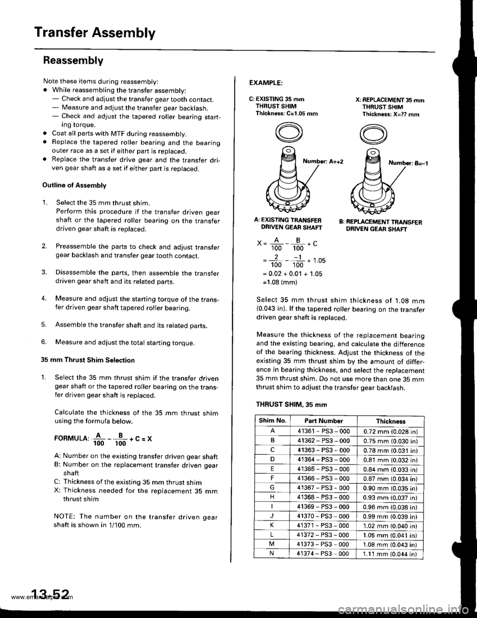
35 mm Thrust Shim Seleqtion
1. Select the 35 mm thrust shim if the transfer drivengear shaft or the tapered roller bearing on the trans-fer driven gear shaft is replaced.
Calculate the thickness of the 35 mm thrust shimusing the formula below.
ronrvruu:fi--fr-+c=x
A: Number on the existing transfer driven gear shaftB: Number on the replacement transfer driven gear
shaft
C: Thickness ofthe existing 35 mm thrust shimX: Thickness needed for the replacement 35 mmthrust shim
NOTE: The number on the transfer driven gear
shaft is shown in 1/100 mm.
2.
3.
13-52
EXAMPLE:
C: EXISTING 35 mmTHRUST SHIMThicknoss: C=1.05 mm
X: REPLACEMET{T35 mmTHRUST SHIMThickness: X=?? mm
Number: A=+2Number: B-l
A: EXISTING TRANSFERDRIVEN GEAR SHAFT
x= A - B -.'- 100 100 -
2-1
100 100 '-
= 0.02 + 0.01 + 1.05-'1.08 (mm)
B: REPLACEMENT TRANSFERDRIVEN GEAF SHAFT
Select 35 mm thrust shim thickness ot '1.08 mm(0.043 in). lf the tapered roller bearing on the transferdriven gear shaft is replaced.
Measure the thickness of the replacement bearingand the existing bearing, and calculate the differenceof the bearing thickness. Adjust the thickness of theexisting 35 mm thrust shim by the amount of differ-ence in bearing thickness. and select the replacement
35 mm thrust shim. Do not use more than one 35 mmthrust shim to adjust the transfer gear backlash,
THRUST SHIM. 35 mm
Shim No.Part NumberThickness
41361 - PS3 - 0000.72 mm (0.028 in)
B41362-PS3-0000.75 mm (0.030 in)
c41363-PS3-0000.78 mm (0.031 in)
41364-PS3-0000.81 mm (0.032 in)
E41365-PS3-0000.84 mm (0.033 in)
F4r366-PS3-0000.87 mm (0.034 in)
41367-PS3-0000.90 mm (0.035 in)
n41368-PS3-0000.93 mm (0.037 in)
41369-PS3-0000.96 mm {0.038 in)
41370-PS3-0000.99 mm (0.039 in)
41371 - PS3 - 0001.02 mm (0.040 in)
L41372-PS3-0001.05 mm (0.041 in)
41373-PS3-0001.08 mm (0.043 in)
N41374-PS3-0001.11 mm (0.044 in)
www.emanualpro.com