Page 1094 of 1395
Component Location
lndex (cont'dl
SRS components are located in this area. Review the SRS component locations, precautions, and procedures in the SRS
section (24) before performing repairs or service.
BLOWER UNITReplacement, page 22-46Ovethaul, page 22 47
/alowen ruoronl
\Test, page 22-16 /
EVAPORATORFeplacement, page 22-48Overhaul, page 22,49
RECIRCULATIONCONTROL MOTORReplacement, page 22 42
HEATER UNITReplacement, page 22 50Overhaul, page 22 52
lest, pag.e 22 42
A/C FILIERReplacement. page 22-50VALVE CABLEAdjustment, page 22-53
RECIRCULATIONCONTROL SWITCH
a/c swtTcH
MODEMOTOR
REAR WINDOWDEFOGGERSwlTCHSee section 23Replacement, page 22-41Test, page 22-41MODE CONTROLDIAL
HEATER CONTROLPANELReplacement, page 22 46
swtTcH
22-4
CONTROL
www.emanualpro.com
Page 1137 of 1395
Overhaul
Note these items when overhauling the blower unit.
. The recirculation contfol motor. the power transistor, the blower motor high relay, and the blower motor can be
replaced without removing the blower unit.
. Betore reassembly, makesurethatthe recirculation control doorand linkage move smoothly without binding.
o After reassembly, make sure the recirculation control motor runs smoothly (se€ page 22-42).
o Make sure that there is no air leakage.
RECIBCULATION CONTBOL MOTORReplacement. page 22-42
BLOWER
m
Tost, page 22-45
POWEB TMNSISTORTest. page 22'44
22-47
www.emanualpro.com
Page 1139 of 1395

}-Overhaul
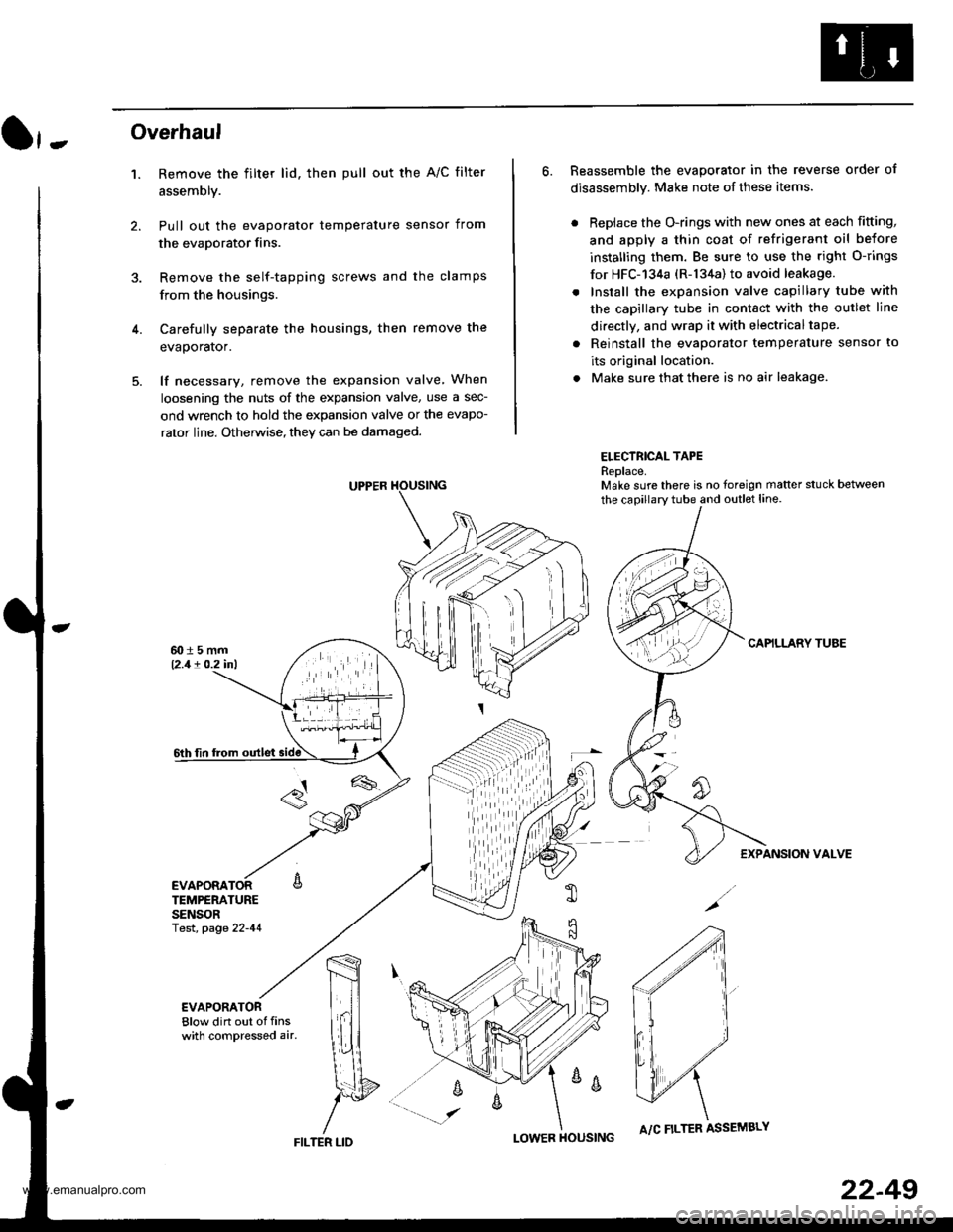
1. Remove the filter lid. then pull out the A/C filter
assembly.
Pull out the evaporator temperature sensor from
the evaporator fins.
Remove the self-tapping screws and the clamps
from the housings.
Carefully separate the housings, then remove the
evaporator.
lf necessary, remove the expansion valve When
loosening the nuts of the expansion valve, use a sec-
ond wrench to hold the expansion valve or the evapo-
rator line. Otherwise, they can be damaged.
6. Reassemble the evaporator in the reverse order of
disassembly. Make note of these items.
. Replace the O-rings with new ones at each fitting,
and apply a thin coat of refrigerant oil before
installing them. Be sure to use the right O-rings
for HFC-'134a (R-134a) to avoid leakage.
. Install the expansion valve capillary tube with
the capillary tube in contact with the outlet line
directly, and wrap it with electricaltape.
. Reinstall the evaporator temperature sensor to
its original location.
. Make sure that there is no air leakage.
ELECTRICAL TAPEReplace.Make sure there is no foreign matter stuck between
the capillary tube and outlet line.
CAPILLARY TUAE
EXPANSION VALVE
4.
TEMPERATURESENSORlest, page 22-41
,m
\!{
YFILTER LID
;
I-OWER HOUSINGA/C FILTER ASSEMBLY
22-49
www.emanualpro.com
Page 1142 of 1395
Heater Unit
Overhaul
1. Remove the self-tapping screws and the heater corecover.
Pull out the grommet from the heater core pipes.
Remove the self-tapping screw and the pipe clamp.
HEATER CORE COVER
Pull out the heate. core. Be careful not to bend the
inlet and outlet pipes during heater core removal.
Reassemble the heater unit in the reverse order of
disassemblv.
HEATER CORE
22-52
www.emanualpro.com
Page 1156 of 1395
Compressor
Glutch Overhaul
1. Remove the center nut while holding the armature
plate with the tool.
A,/C CLUTCH HOLOERlCommerciallY .vailable)Robinair: P/N 1020,0Ked-Mooro: P/N J37872
CENTER NUT17.6 N.m ('1.8 kgf.m, 13lbfft)Reolace. \
i
2. Remove the armature plate by pulling it up by hand.
ARMATURE PLATE
sHtMls)Replace.
za:s
(i@,
22-66
3. Remove the snap ring B with snap ring pliers. Be
careful not to d8mage the rotor pulley and com-
pressor.
SNAP RING BR6place.
Remove the rotor pulley from the shaft with the
tools. Be sure the claws ot the puller are on the back
of the rotor pulley, not on the belt area; otherwise
the rotor pulley can be damaged.
www.emanualpro.com