1999 HONDA CR-V Pin out
[x] Cancel search: Pin outPage 28 of 1395
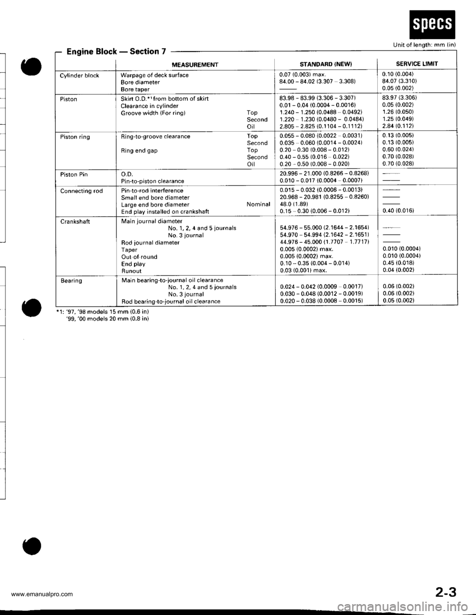
Engine Block - Section 7
o
o*1: '97,'98 models 15 mm (0.6 in)'99,'00 models 20 mm (0.8 ini
Unit of length: mm (in)
MEASUREMENTSTANDARD (NEWISERVICE LIMIT
Cylinder blockWarpage of deck surfaceBore diameterBore taper
0.07 (0.003) max.84.00 - 84.02 (3.307 3.308)0.10 (0.004)
84.07 (3.310)
0.05 (0.002)
PistonSkirt O.D.*1trom bottom of skartClearance in cylinderGroove width {For ringi TopSecondoil
83.98 - 83.99 (3.306 - 3.307)0.01 - 0.04 (0.0004 - 0.001611.240 - 1.250 {0.0488 - 0.0492)1.220 1.230 {0.0480 - 0.0484)2.805 2.825 10.1104 - 0.1112)
83.97 (3.306)
0.05 {0.002)1.26 (0.0s0)
1.25 (0.049)
2.44lo.112l
Piston ringRing-to'groove clearance ToPSecondRing end gap ToPSecondoil
0.055 - 0.080 (0.0022 0.0031)0.035 0.060 (0.0014 - 0.0024)0.20 0.30 (0.008 - 0.012)0.40 - 0.55 (0.016 0.022)0.20 - 0.50 (0.008 - 0.020)
0.13 (0.005)
0.13 (0.005)
0.60 (0.024)
0.70 (0.028)
0.70 (0.028)
Piston Pino.D.Pin-to-piston clearance
20.996 - 21.000 (0.8266 - 0.8268i0.010 - 0.017 (0.0004 - 0.0007)
Connecting rodPin-to-rod interferenceSmall end bore diameterLarge end bore diameter NominalEnd play installed on crankshaft
0.015 - 0.032 (0.0006 - 0.0013)20.968 -20.981 10.8255 -0.8260)
48.0 (1.89)
0.15 - 0.30 {0.006 - 0.012ioro to.oroi
CrankshaftMain journaldiameter
No. 1,2,4 and 5 iournalsNo. 3 journal
Rod iournal diameterTaperOut ol roundEnd play
Bunout
54.976 - 55.000 (2.'�l644 - 2.1654)54.970 54.994 (2.1642 - 2.1651)44.976 - 45.000 /.1.1707 - 1.711110.005 (0.0002)max.
0.005 (0.0002) max.0.10 - 0.35 (0.004 - 0.0 r 4)0.03 (0.001)max.
0.010 (0.00041
0.010 (0.0004)
0.45 (0.0r8)
0.04 (0.002)
BearingMain bearing-to-iournal oil clearanceNo. 1, 2, 4 and 5 iournalsNo. 3 journal
Rod bearing-to-,ournal oil clearance
0.024 - 0.042 10.0009 0.0017)0.030 - 0.048 (0.0012 - 0.0019)0.020 - 0.038 (0.0008 0.0015)
0.06 (0.002)
0.06 (0.002)
0.05 (0.002)
o
2-3
www.emanualpro.com
Page 29 of 1395
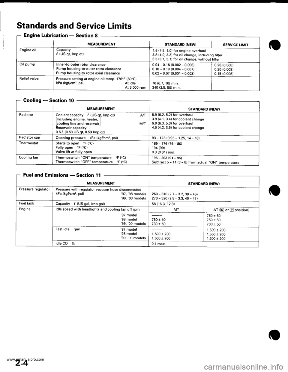
Standards andService Limits
Engine LubricationSection 8
CoolingSection 10
Fuel and EmissionsSection 11
MEASUREMENTSTANDARO {NEWISERVICE LIMIT
Engine oilCapacityf (US qt, lmp qt)4.6 (4.9, 4.0)Ior engine overhaul3.8 {4.0,3.3)for oilchange, including filter3.5 (3.7, 3.1) for oil change, without Iilter
OilpumpInner-to-outer rotor clearancePump housing-to-outer rotor clearancePump housing-to rotor axial clearance
0.04 - 0.16 (0.002 - 0.006)0.10 -0.19 (0.004 - 0.007)0.02 -0.07 (0.001 - 0.003i
0.20 (0.008)
0.20 (0.008)
0.15 (0.006)
Relief valvePressure setting at engine oil temp. 176'F (80'C)kPa (kgt/cm,, psi) At ldleAt 3,000 rpm70 (0.7, 10) min.340 {3.5,50) min.
MEASUREMENTSTANDARO INEW}
RadiatorCoolant capacity , (US q1, lmp qt)
llncluding engine, heater, ILcooling line and reservoirlReservoir capacity:0.61 (0.63 US qt,0.53lmp qt)
M/T
5.9 {6.2, 5.2}tor overhaul3.9 (4.1, 3.4ifor coolant change6.0 (6.3, 5.3ifor overhaul4.0 (4.2, 3.5) for coolant change
Radiator capOpening pressure kPa (kgf/cm?, psi)93 - 123 (0.95 - 1.25, 14 18)
ThermostatStarts to open 'F 1"C)Fully open 'F ("C)
Valve lift at tully open
169 - 176 (76 - 80)194 (90)
8.0 (0.31imin.
Cooling fanThermoswitch "ON" temperature "F {'C)Thermoswitch "OFF" temperature 'F ('C)196 - 203 (91 - 95)Subtract 5 - 14 (3 - 8) trom actual "ON" temperature
MEASUREMENTSTANDARD INEW}
Pressure regulatorPressure with regulator vacuum hose disconnectedkPa (kgflcm'�, psi) '97,'98 models'99, '00 rnodels260 - 31012.7 3.2,38- 46)270 -32012.8 3.3,40 - 471
FueltankCapacity / (US gal, lmp gal)58 (15.3, 12.8)
E ngineldle speed with headlights and cooling fan off rpm'97 model'98 model'99, '00 models
MTAT {E or E position)
750 r 50730 1 50
750 t 50750 r 507301 50
Fast idle rpm '97 model'98 model'99, '00 models1,5001 2001,600 r 200
1,5001 2001,5001 2001,600 r 200
ldle CO %0.1 max.
2-4
www.emanualpro.com
Page 34 of 1395
2-9
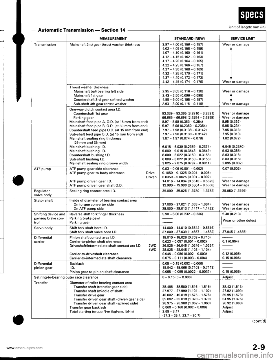
Automatic Transmission - Section 14
o
Unit of length: mm (in)
o
MEASUREMENTSTANDARD (NEWISERVICE LIMIT
TransmissionMainshaft 2nd gear thrust washer thickness3.97 - 4.00 10.156 - 0.157)4.02 - 4.05 {0.158 - 0.159)4.07 - 4.1010.160 0.161)4.12 - 4.15 (0.162 - 0.163)4.17 4.20 (0.164 0.165)4.22 - 4.25 10.166 - 0.167 )4.27 - 4.30 (0.168 - 0.169)4.32 4.35 (0.170-0.171)
4.37 - 4.40 (0.172 0.173)4.42 - 4.45 (0.174 - 0. r75)
I
I
IWear or damage
Thrust washer thicknessl'rainshaft ball bearing left sideMainshaft 1st gear
Countershaft 3rd gear splined washerSub-shaft 4th gear thrust washer
2.95 3.05 (0.116 0.120)2.43 - 2.50 (0.096 - 0.098)4.9s - 5.00 (0.195 - 0.197)2.93 - 3.00 (0.115 - 0.1181
Wear or damage
tIWear or damage
One-way clutch contact area LD.Countershaft 1st gearParking gearMainshaft feed pipe A, O.D. (at 15 mm trom end)Mainshaft feed pipe B, O.D. (at 30 mm from end)Countershaft teed pipe O.D. lat 15 mm from end)Sub-shaft feed pipe O.D. (at 15 mm from end)Mainshatt sealing ring thickness(29 mm and 35 mm)Mainshaft bushing I.D.Mainshaft bushing l.D.Countershaft bushing l.D.Sub shatt bushing LD.Mainshaft sealing ring groove width
83.339 83.365 (3.2810 3.2821)66.685 - 66.698 (2.6254 - 2.6259)8.97 - 8.98 (0.353 - 0.354)5.97 5.98 {0.2350 - 0.2354)7.97 - 7.98 (0.3138 - 0.3142)7.97 ,7.98 (0.3138 - 0.3142)1.87 - 1.97 (0.074-0.078)
6.018 - 6.030 (0.2369 - 0.2374)9.000 - 9.015 (0.3543 - 0.3549)8.000 - 8.022 (0.3150-0.3158)
8.000 - 8.022 (0.3150 0.3158)2.025 - 2.075 (0.0797 0.0811)
Wear or damageWear or damage8.95 (0.352)
5.95 (0.234)
7.95 (0.313)
7.95 {0.313)1 .42 $.O72)
5.045 (0.2380)
9.03 (0.356)
8.03 (0.316)
8.03 (0.316)
2.095 (0.082)
ATF pumpATF pump gear side clearanceATF pump gear'to body clearance DriveDrivenATF pump driven gear LD.ATF pump driven gear shaft O.D.
0.03 - 0.05 (0.001 - 0.002)0.1050 0.1325 (0.004, 0.005)0.0350 - 0.0625 10.001 - 0.002)14.016* 14.034 (0.5518 0.5525)13.980 - 13.990 {0.5504 0.5508)
0.0710.003)
Wear or damageWear or damage
Regulatorvalve bodySealing ring contact area l.D,35.000 35.025 {1.3780 - 1.3782)35.050 (1.3799)
Stator shaftInside of diameter oI bearing contact areaOn torque convener sideOn ATF pump side2't .o00 27 .021 I '1 .063 , 1 .064)29.000 - 29.01311.r417 1.1422)Wear or damageWear or damage
Shifting device andparking brake con'trol
Reverse shitt fork finger thicknessParking brake pawl
Parking gear
5.90 - 6.00 {0.232,0.236)5.40 (0.213)
lWear or other defect
Servo bodyShift fork shatt bore l.D.Shift fork shatt valve bore l.D.14.000 - 14.010 (0.55'�l2 - 0.5516)37.000 - 37.039 (1.4567 - 1.4582)37.045 (1.4585)
DifferentialcarrierPinion shaft contact area LD.Carrierto-pinion shaft clearanceDriveshafvintermediate shaft contact are l.D. 2WD4WDCarrier to driveshalt clearanceCarrier-to-intermediate shaft clearance
'18.010 - 18.028 10.709 - 0.710)0.023 - 0.057 {0.001 - 0.002}26.025 - 26.045 (1.0246 - 1.0254)28.025 - 28.045 (1.103 - 1.104)0.045 - 0.08610.002 0.003)0.075 - 0.111 10.003- 0.004)
0.r {0.004)
0.12 (0.005)
0.15 (0.006)
Differentialprnron gearBacklasht.D.Pinion gear'to-pinion shaft clearance
0.05 - 0.15 (0.002 - 0.006)18.062 - 18.066 (0.7103 - 0.7113)0.055 - 0.095 10.0022 - 0.0037)otu to.oout
Set ring-to-bearing outer race clearance0 0.15 (0 - 0.006)Adjust
TransferDiameter of roller bearing contact areaTransfer shaft (transfer gear side)Transfer shaft (middle of shaft)Transfer drive gearTransfer driven gear shaft {driven gear side)Transfer driven gear shaft {splined side)Transfer gear backlashTotalstarting torque N.m (kgf.cm, lbf.in)
38.485 38.500 (1.515 - 1.516)27 .917 - 21 .990 |.1.101 - 1.102)40.002 - 40.018 (1.575 - 1.576)35.002 35.018 (1.378 - 1.379)26.975 26.988 (1.062 -'�l.063)
0.060 0.160 (0.002 - 0.006)2.64 - 3.41127.3 - 35.4,23.1 30.71
38.43 (1.513)
27.92 (1.099)
39.95 (1.573)
34.95 (1.376)
26.92 (1.060)
AdiustAdiust
(cont'd)
www.emanualpro.com
Page 63 of 1395
,r1.?
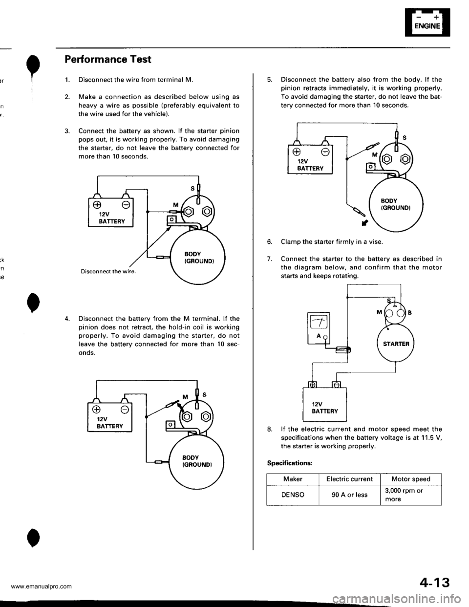
Performance Test
Disconnect the wire from terminal N4.
Make a connection as described below using as
heavy a wire as possible (preferably equivalent to
the wire used for the vehicle).
Connect the battery as shown. lf the starter pinion
pops out. it is working properly. To avoid damaging
the starter, do not leave the battery connected for
more than 10 seconds.
3.
ie
Disconnect the battery from the M terminal. lf the
pinion does not retract, the hold-in coil is working
properly. To avoid damaging the starter, do not
leave the battery connected for more than 10 sec
onds.
@o12VBATTERY
4-13
5. Disconnect the battery also from the body. lf the
pinion retracts immediately, it is working properly,
To avoid damaging the starter, do not leave the bat-
terv connected for more than 10 seconds.
6.
7.
Clamp the starter firmly in a vise.
Connect the starter to the battery as described in
the diagram below, and confirm that the motor
starts and keeps rotating.
8, lf the electric current and motor soeed meet the
specifications when the battery voltage is at 11.5 V,
the starter is working properly.
Specifications:
MakerElectric currentMotor speed
DENSO90 A or less3,000 rpm or
more
www.emanualpro.com
Page 143 of 1395
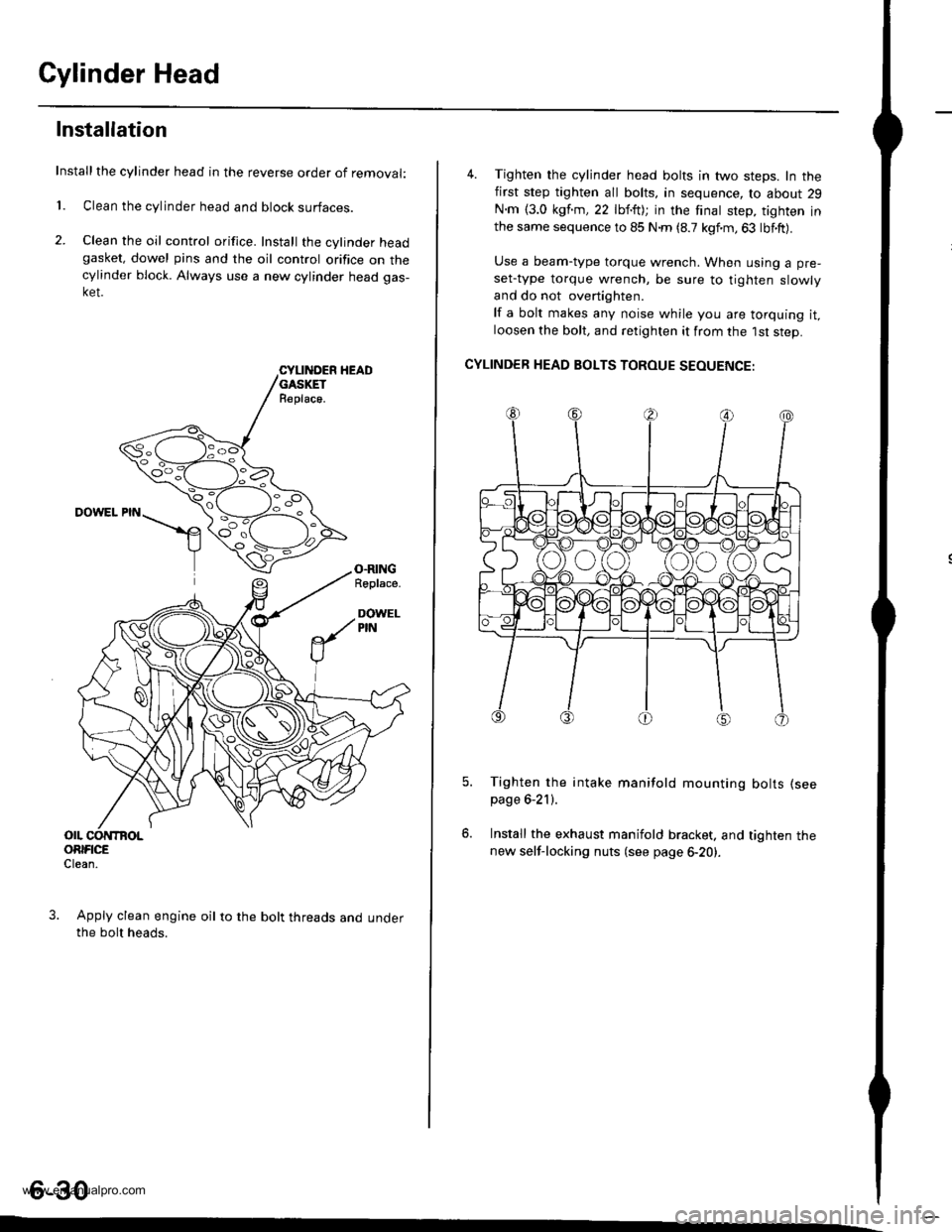
Cylinder Head
Installation
Installthe cylinder head in the reverse order of removal:
1. Clean the cylinder head and block surfaces.
2. Clean the oil control orifice. Install the cylinder headgasket, dowel pins and the oil control orifice on thecylinder block. Always use a new cylinder head gas-ket.
CYLII{DER HEADGASKETR€place.
DOWEL PIN
O.RINGRoplace.
DOWELPIN
OIL CONTBOLORIFICEClean.
Apply clean engine oil to the bolt threads and underthe bolt heads.
4. Tighten the cylinder head bolts in two steps. In thefirst step tighten all bolts, in sequence, to about 29
N.m {3.0 kgf.m,22 lbf.ft); in the finat step, tighten inthe same sequence to 85 N.m (8.7 kgf.m,63 lbf.ft).
Use a beam-type torque wrench. When using a pre-
set-type torque wrench, be sure to tighten slowly
and do not overtighten.
lf a bolt makes any noise while you are torquing it,loosen the bolt, and retighten it from the 1st step.
CYLINDER HEAD BOLTS TOROUE SEOUENCE:
Tighten the intake manifold mounting bolts (see
page 6-21).
Install the exhaust manifold bracket. and tighten thenew self-locking nuts (see page 6-20).
6-30
www.emanualpro.com
Page 145 of 1395

Cylinder Head
Installation (cont'dl
'13. Align the marks on the cylinder head plug to thecylinder head upper surface, then install the cylin
der head plug in the end of the cylinder head.
CYLINOER HEADPLUGReplace.
lnstallthe back cover.
To set the camshafts at TDC position for the No. lpiston, align the holes in the camshafts with theholes in the No. l camshaft holders and insert 5.0mm pin punches in the holes. Install the keys into
the camshaft grooves.
37 N m (3.8 *gl.m, 27 lbt.tr)
9.8 N.m (1.0 kgtm,7.2|hrftl
Push the camshaft pulleys onto the camshafts. thentighten the retaining bolts to the torque specified.
6-32
14.
KEYS
I x 1.25 mm
6x1.0mm
Install the timing belt (see page 6-1 1).
Adjust the valve clearance (see page 6-3).
Thoroughly clean the head cover gasket and thegroove.
lnstall the head cover gasket in the groove of thecylinder head cover. Seat the head cover gasket in
the recesses for the camshaft first, then work it into
the groove around the outside edges. Make sure thehead cover gasket is seated securely in the corners
of the recesses with no gap.
17.
'18.
19.
www.emanualpro.com
Page 149 of 1395
lllustrated lndex
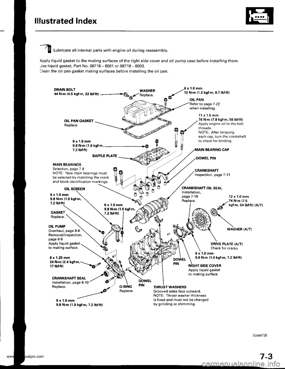
I Luori""t" "tl internal parts with engine oil during reassembly.
Apply liquid gasket to the mating surfaces of the right side cover and oil pump case before installing them.
Jse liquid gasket, Part No. 08718 - 0001 or 08718 - 0003.
:lean the oil pan gasket mating surfaces before installing the oil pan.
WASHERReplace.
76 x 1.0 mm
y' t:n- l.zxstm, 8.7 lbl ftl
9 oIL PAN
OIL PAN GASKETReplace.
to page 1-22when installing
BEARING CAP
OOWEL PIN
CRANKSHAFT OIL SEAL
11x 1.5 mm76 N.m {7.8 kgl.m, 56 lbf.ft}Appiy engine oilto the boltthreaos.NOTE: After lorquingeach cap, turn the crankshaftto check for binding.6x1.0mm9,8 N.m (1,0 kgf.m,7 .2 tbt.lrl
n
MAIN BEARINGSSelection, page 7 8NOTE: New main bearings mustbe selected by matching the crankand block identification markings.
otL
6 x'1.0 mm9.8 N.m {1.0 kgtm,7.2 tbf.ftl
BAFFI.f PLATE
9.8 N.m 11.0 kgt m,7.2 tbt+tl
12 x 1.0 mm
/,71N n 17 .5
&it ks{ m 5a lbtft) {a/Tl
GASKETReplace.
OIL PUMP
Installation,page 7-19Replace.
ln
6WASHER IA/T}Overhaul, page 8-8Removal/lnspection,page 8-9Apply liquid gasketto mating surface.
8 x 1.25 mm
ORIVE PLATE IA/T)Check for cracks.
6x1.0mm9.8 N.m 11.0 kgt.m,7.2 lbtft)2a N.m (2.a kgt.m,---\6/
CRANIGHAFT SEALInstallation, page 8-10Replace-
6x1.0mm9.8 N.m l'1.0 kgf.m,7.2 lbf.ft)
RIGHT SIDE COVERApply liquid gasketto mating surface,
O.RINGReplace.THRUST WASHERSGrooved sides face outlvard,NOTE: Thrust washer thicknessis lixed and must not be changedby grinding or shimming.
(cont'd)
7-3
6x1.0mm
www.emanualpro.com
Page 160 of 1395
Piston PinsConnecting Rods
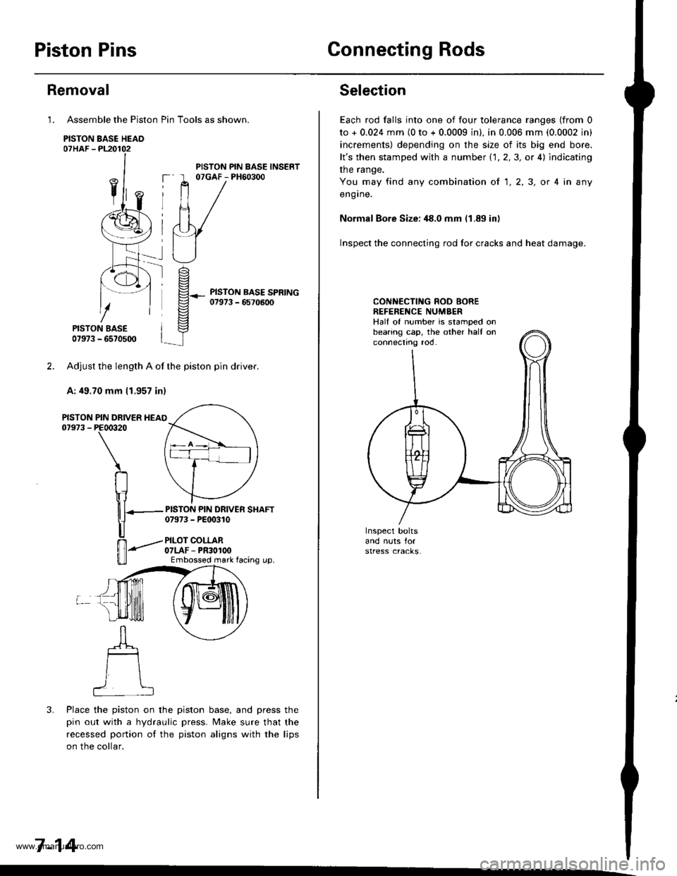
Assemble the Piston Pin Tools as shown.
PISTON BASE HEAO07HAF -PL20102
PISTON BASE07973 - 6570500
Adjust the length A of the piston pin dflver.
A: 49.70 mm 11.957 in)
PIN DRIVER HEAIPE00320
\
RIr1
nT---
u
ffi-"""-
u_ll
3. Place the piston on the piston base, and press the
pin out with a hydraulic press. Make sure that the
recessed portion of the piston aligns with the lips
on the collar.
7-14
Removal
1.
PISTON07973 -
PISTON PIN BASE INSERT07GAF - PH60300
PISTON PIN DRIVER SHAFT07973 - PEt 0310
PILOT COLLAR07LAF - PR30100Embossod mark facing up.
Selection
Each rod falls into one of four tolerance ranges (from 0
to + 0.024 mm {0 to + 0.0009 in). in 0.006 mm (0.0002 in)
increments) depending on the size of its big end bore.
lt's then stamped with a number 1.1.2,3, or 4) indicating
the range.
You may find any combination ot 1,2,3, or 4 in any
engrne.
Normal Bore Size: ,18.0 mm (1.89 in)
Inspect the connecting rod for cracks and heat damage.
CONNECTING ROD BOREREFENENCE NUMBERHalf of number is stamped onbearing cap, the other half onconnectno roo.
www.emanualpro.com