Page 747 of 1395
Reverse ldler GearPark Stop
lnstallation
1. lnstall the reverse idler gear'
lnstallthe reverse idler gear shaft holder and needle
bearing into the transmission housing, then tighten
the bolts.
6 x 1.0 mm12 N.ft ll.2 kgl']n,a.7 rbl.frl
't.
Inspection/Adi ustment
Set the park lever in the E position.
Measure the distance between the park pawl shaft
and the park lever roller pin as shown.
STANDARD: 72.9 - 73.9 mm {2.87 - 2.91 in)
PARK STOP
PARK PAWL SHAFT
lf the measurement is out of standard, select and
install the appropriate park stop from the table
below.
PARK STOP
PARK STOP
After replacing the park stop. make sure the dis-
tance is within standard.
',.�A\
Measuring /
MarkPart NumberLtL2
124537-PAg-00311.00 mm
(0.433 in)
11.00 mm
(0.433 in)
24538-PAg-00310.80 mm
(0.425 in)
10.65 mm
(0.419 in)
24539-PAg-00310.60 mm
(0.417 in)
10.30 mm
(0.406 in)
14-231
www.emanualpro.com
Page 777 of 1395

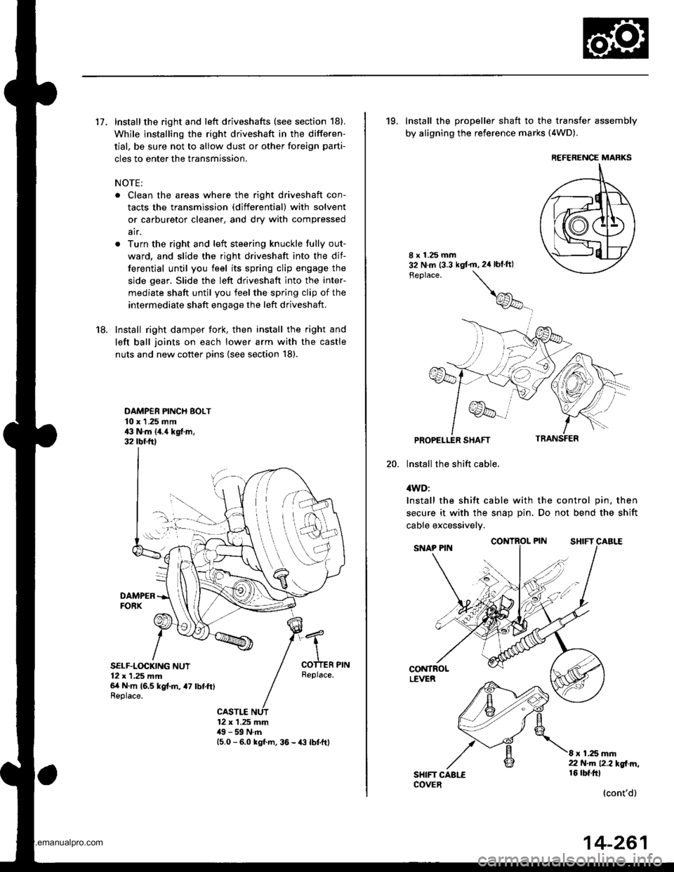
17. Install the right and left driveshafts (see section 18).
While installing the right driveshaft in the differen-
tial, be sure not to allow dust or other foreign parti-
cles to enter the transmission.
NOTE:
. Clean the areas where the right driveshaft con-
tacts the transmission (differential) with solvent
or carburetor cleaner, and dry with compressed
air.
. Turn the right and left steering knuckle fully out-
ward, and slide the right driveshaft into the dif-
ferential until you feel its spring clip engage the
side gear. Slide the left driveshaft into the inter-
mediate shaft until you feel the spring clip of the
intermediate shaft engage the left driveshaft,
18. Install right damper fork, then install the right and
left ball joints on each lower arm with the castle
nuts and new cotter pins (see section 18).
DAMPER PINCH BOLT10 x 1 .25 mm43 N.m 14.{ kgf.m,32 rbr.ftl
DAMPERFORX
SELF.LOCKING NUT12 x 1,25 mm6/t N m (6.5 kg{.m, a7 lbtft)Replace.
Replace.
CASTLE12 x 1.25 mm49 - 59 N.m15.0 - 6.0 kgl m, 36 - {3 lbtftl
19, Install the propeller shaft to the transfer assembly
by aligning the reference marks (4WD).
20.
8 x 1.25 mm32 N.m (3.3 kgt'm,2ir blft)
Feplace.
\
@_
PROPELLER SHAFT
lnstall the shift cable.
4WD:
Install the shift cable with the control pin, then
secure it with the snap Din. Do not bend the shift
cable excessivelv.
CONTROLLEVER
SHIFT CAALECOVER
8 x 1.25 mm22 N.m 12.2l'gl m,16 rbt.ftl
(cont'd)
REFERENCE MARKS
14-261
www.emanualpro.com
Page 788 of 1395

Shift Gable
Adjustment
SRS components are located in this area. Review the SRS
component locations, precautions, and procedures in the
SRS section (241 before performing repairs or service.
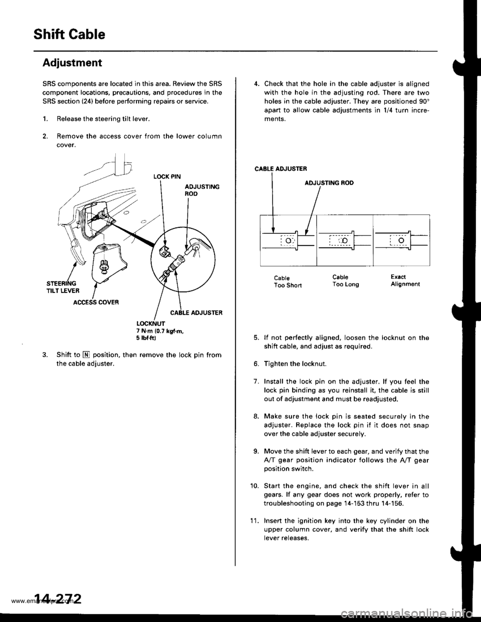
1. Release the steering tilt lever.
2. Remove the access cover from the lower column
cover.
LOCK PIN
AOJUSTINGnoo
ADJUSTER
7 N.m (0.7 kg{.m,5 tbf.ft)
3. Shift to E position. then remove the lock pin from
the cable adjuster.
K\ffi
/* 1 6-,>
snenrftc YTILT LEVER IACCESS COVER
14-272
'l 1.
4. Check that the hole in the cable adjuster is aligned
with the hole in the adjusting rod. There are two
holes in the cable adjuster. They are positioned 90"
apart to allow cable adjustments ln l/4 turn incre-
ments.
CABLE ADJUSTER
CablsToo Short
lf not perfectly aligned, loosen the locknut on the
shitt cable. and adjust as required.
Tighten the locknut.
Install the lock pin on the adjuster. lf you feel the
lock pin binding as you reinstall it, the cable is still
out of adjustment and must be readjusted.
Make sure the lock pin is seated securely in the
adjuster. Replace the lock pin if it does not snap
over the cable adjuster securely.
Move the shift lever to each gear, and verify that the
A/T gear position indicator follows the A"/T gear
position switch.
Start the engine, and check the shift lever in all
gears. lf any gear does not work properly, refer to
troubleshooting on page 14-'153 thru 14-156.
Insert the ignition key into the key cylinder on the
upper column cover, and verify that the shift lock
tever reteases.
CableToo LongExactAlignment
7.
a
10.
www.emanualpro.com
Page 794 of 1395

Description
Rear Differential
Outline
The Real-time 4WD-Dual Pump System model has a hydraulic clutch and a differential mechanism in the rear differential
assembly. Under normal conditions, the vehicle is driven by the front wheels. However, depending on to the driving force
of the front wheels and the road conditions. the system instantly transmits appropriate driving force to the rear wheels
without requiring the driver to switch between 2WD (tront wheel drive) and 4WD (four wheel drive). The switching mecha-
nism between 2WD and 4WD is integrated into the rear differential assembly to make the system light and compact.
ln addition, the dual-pump system switches off the rear-wheel-drive force when braking in a forward gear. This allows the
braking system to work properly on models equipped with an Anti-lock Braking System (ABS).
Construction
The rear differential assembly consists of the torque control differential case assembly and the rear differential carrier
assembly. The torque control differential case assembly consists of the differential clutch assembly, the companion
flange, and the oil pump body assembly. The rear differential carrier assembly consists of the differential mechanism. The
differential drive and driven gears are hypoid gears.
The oil pump body assembly consists of the front oil pump, the rear oil pump, the hydraulic control mechanism, and the
clutch piston. The clutch piston has a disc spring that constantly provides the differential clutch assembly with a preset
torque to Drevent abnormal sound.
The clutch guide in the differential clutch assembly is connected to the propeller shaft via the companion flange, and it
receives the driving force lrom the transfer assembly. The clutch guide rotates the clutch plate and the front oil pump in
the oil pump body.
The clutch hub in the differential clutch assembly has a clutch disc that is splined with the hypoid drive pinion gear. The
hypoid drive gear drives the rear oil pump.
The front and rear oil pumps are trochoidal pumps. The rear oil pump capacity is 2.5 percent larger that the front oil pump
to handle the rotation difference between the front and rear wheels caused by worn front tires and tight corner braking.
The oil pumps are designed so the fluid intake works as a fluid discharge when the oil pumps rotate in reverse. Genuine
Honda CVT fluid is used instead of differential fluid.
Operation
When there is a difference in rotation speed between the front wheels (clutch guide) and rear wheels (hypoid driven gear),
hydraulic pressure from the front and rear oil pumps engages the differential clutch, and drive force from the transler
assembly is applied to the rear wheels.
The hydraulic pressure control mechanism in the oil pump body selects 4WD mode when the vehicle is started abruptly,
or when accelerating in a forward or reverse gear (causing rotation difference between the front and rear wheels). or
when braking in reverse gear {when decelerating). lt switches to 2WD mode when the vehicle is driven at a constant speed
in forwar! or reverse gear (when there is no rotation difference between the front and rear wheels), or when braking in a
fo rwa rd gear (when decelerating).
To protect the system, the differential clutch assembly is lubricated by hydraulic pressure generated by the oil pumps in
both 4WD and 2WD modes. Also, the thermal switch relieves the hydraulic pressure on the clutch piston and cancels 4WD
mode if the temDerature of the differential fluid rises above normal.
www.emanualpro.com
Page 811 of 1395
3. Installthe speclaltools on the companion flange,
HOIIIER HANDTIo'JAB - OO102nA
32 N m {3 3 tgt m,24lbf ftl
Loosen the locknut counterclockwise so that its tab
comes out from the groove in the clutch guide.
LOCKNUT, 24 mm
Tighten the locknut till its tab aligns with the groove.
Remove any dirt from inside of the groove in the
clutch guide, then loosen the locknut.
LOCKNUT. 2,1 mm
5.
6.
8 x 1.25 mm
Tab(cont'd)
7. Remove the locknut, the disc spring washer, the
back-up ring, the O-ring and the companion flange.
@r/v-.,.
ao/
U
rA*..-
zzft
h\@fr\
LOCKNUT, 24 mmFeplace.
DISC SPRING WASHER, 24 mm
BACX.UP RING
O.N|NGReplace.
COMPANION FLANGE
8.Remove the torque control differential case and the
dowel pins.
www.emanualpro.com
Page 819 of 1395

Front Driveshafts
Removal (cont'd)
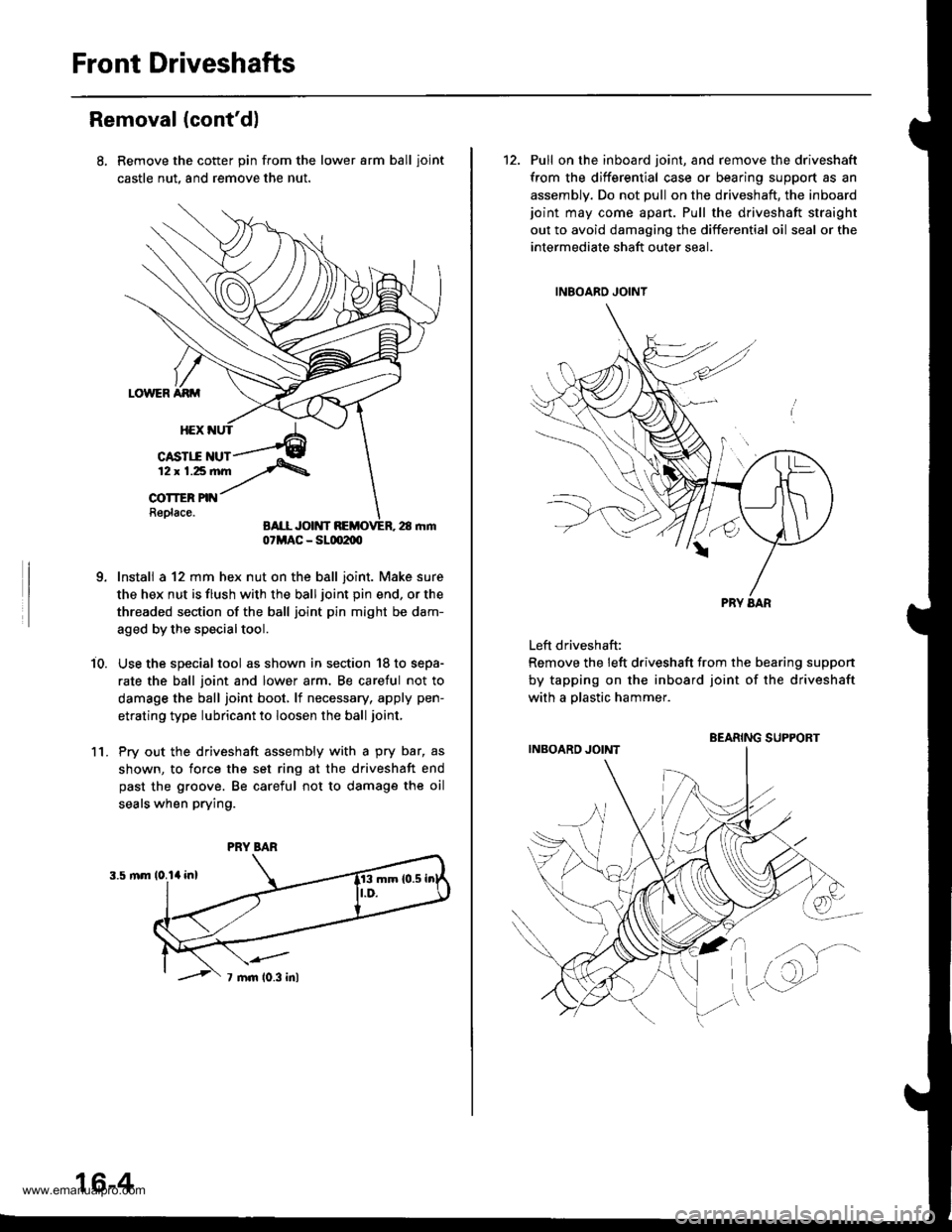
Remove the cotter pin from the lower arm ball ioint
castle nut, and remove the nut.
Install a 12 mm hex nut on the ball joint. Make sure
the hex nut is flush with the ball joint pin end, or the
threaded section of the ball joint pin might be dam-
aged by the special tool.
Use the special tool as shown in section '18 to sepa-
rate the ball joint and lower arm, Be caretul not to
damage the ball joint boot, lf necessary, apply pen-
etrating type lubricant to loosen the ball joint,
Pry out the driveshaft assembly with a pry bar, as
shown, to force the set ring at the driveshaft end
past the groove. Be careful not to damage the oil
seals when prying.
i0.
1l.
07MAC - SLm2m
PRY BAR
16-4
12. Pull on the inboard joint, and remove the driveshaft
from the differential case or bearing support as an
assembly. Do not pull on the driveshaft, the inboardjoint may come apart. Pull the driveshaft straight
out to avoid damaging the differential oil seal or the
intermediate shaft outer seal.
Left driveshaft:
Remove the left driveshaft from the bearing suppon
by tapping on the inboard joint of the driveshaft
with a olastic hammer.
BEARING SUPPORT
www.emanualpro.com
Page 827 of 1395
Front Driveshafts
Reassembly (cont'd)
16. Unwind the boot band tool. and cut off the excess
free end of the band to leave a 5 - 10 mm (0.2 - 0.4
in) tail protruding from the clip.
5- 10 mm
10.2 - 0.4 in,
Bend the band end by tapping it down with a ham-
mer,
NOTE;
. Make sure the band does not move,
. Remove any grease remaining on the surround-
ing surfaces.
18, Install the new set ring.
17.
16-12
Outbosrd Joint Sids:
1. Wrap the splines with vinyl tape to prevent damage
to the boot.
OUTBOARD BOOT
2, Install the boot band and outboard boot, then
remove the vinyl tape. Take care not to damage the
boot.
3. Install the stop ring into the driveshaft groove.
VINYL TAPE
DRIVESHAFT
www.emanualpro.com
Page 829 of 1395
Front Driveshafts
8. Fit the boot ends onto the driveshaft and outboard
lornt.
OUTBOARD BOOT fiPE)
OUTBOARD BOOT
OUTBOARD BOOT
Reassembly (cont'd)
Install the boot bands,
. For all '97 models and'98
step 13.
. For'98 Canada models andgo to step 10.
OUTBOARD JOINT
USA models, go to
all '99 - 00 models,
10. Set the ear clamp band by threading the tab into theholes of the band.
16-14
11. Close the ear portion of the band with a commercially
available boot band pincers KENT-MOORE J-35910 or
equivalent.
BOOT BAND PINCERSKENT.MOORE J-35910or equivalent
12.Check the clearance between the closed ear Dortionof the band, lf the clearance is not within the stan-dard, close the ear portion of the band further.
6.0 mm 10.24 in) MAX
3.0 mm {0.12 in} MAX
EAR PORTION
www.emanualpro.com