Page 178 of 1395
Oil Pump
Overhaul
6xl.0mm9.8 N m (1.0 kg,t m, 7.2 lbf ftl
6x1.0mm5 N.m {0.5 kgt m. 4lbtft}OUTER ROTORInspection, pages 8-9, 1O
PUMP COVER
lnspection, pages 8-9, 10Apply liquid gasketto the mating surface ofthe cylinder blockwhen anstalling.
REI-IEF VALVEValve must slide freelyin the housing bore.Replace the valve if it is scored.
8 x 1.25 mm2{ N.m (2.4 kgf m,17 tbf.fi)
DOWEL PIN
8-8
www.emanualpro.com
Page 440 of 1395

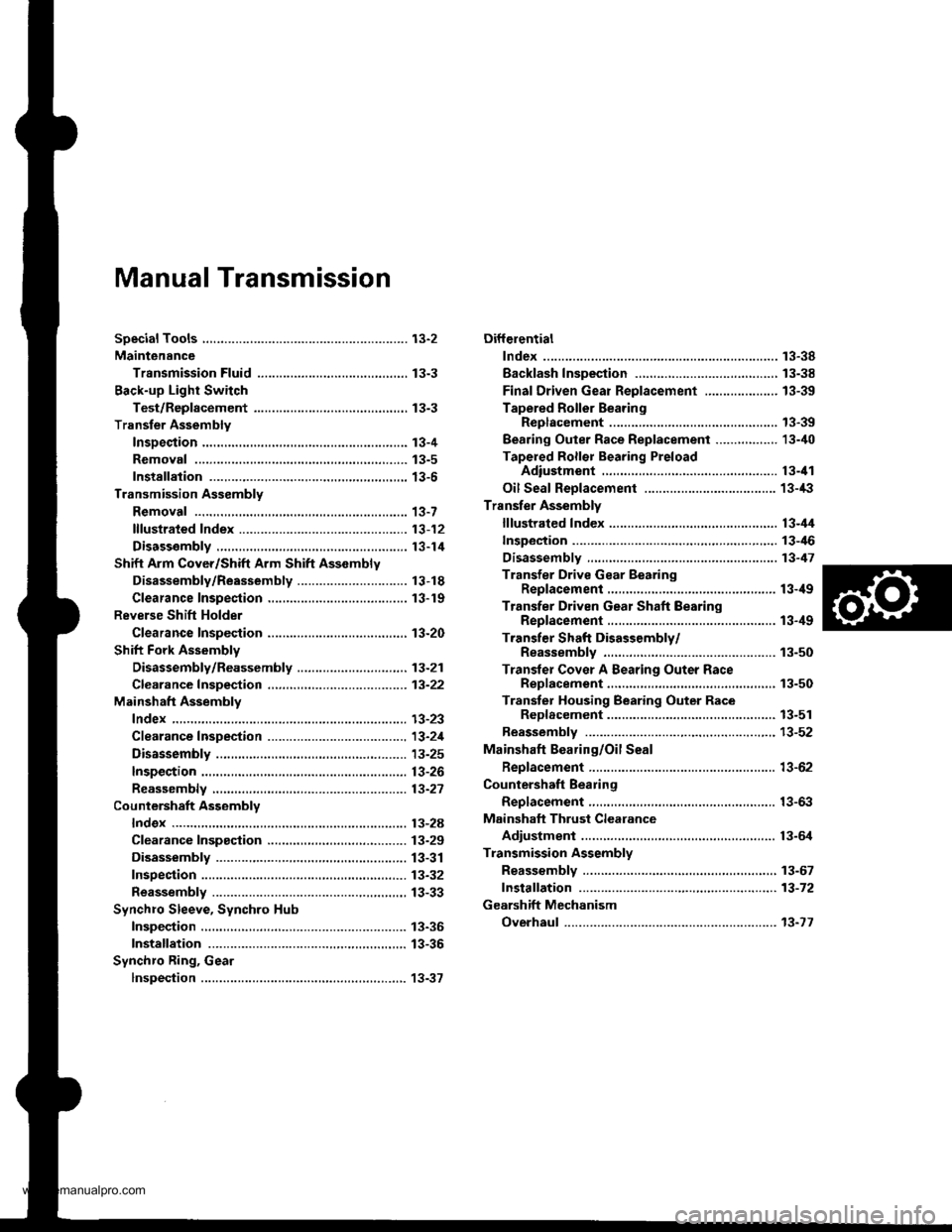
Manual Transmission
Diff€rential
lndex ...................... ......... 13-38
Backlash Inspestion ..,....,.,.....................,......, 13-38
Final Driven Gear Replacement .................... 13-39
Tapered Roller BearingReplacement ............. 13-39
Bearing Outer Race Replacement ......,.,........ 13-i10
Tapered Roller Bearing PreloadAdiustment ............... 13-il1
Oil Seal Reolacement .................................... 13-/l:}
Transfer Assembly
lllustrated Index ............. 13-il4
Inspection ..,....,.,......,...... 13-46
Disassembly ................... 13-47
Transfer Drive Gear BearingReplacement ...,..................,....................... 13-ilg
Transfer Driven Gear Shaft BearingReplacement .............................................. 13-ilg
Transfer Shaft Disassembly/Reassembly .............. 13-50
Transler Cover A Bearing Outer RaceRep1acement.........,.,.,..........,....,...,.........,., 13-50
Transter Housing Bearing Outer RaceReD1acement.............................................. 13-51
Reassembly ..-............,... 13-52
Mainshaft Bearing/Oil Seal
Beplacement .................. 13-62
Countershaft Bearing
Replacement .,,.,.,., ..,...... 13-63
Mainshaft Thrust Clearance
Adiustment .................... 13-6,1
Transmission Assembly
Reassembly .,.,.,.,..,.,....,., 13-67
fnstaffation .,.,.............,... 13-72
Gearshift Mechanism
Overhaul ................ .........13-17
www.emanualpro.com
Page 442 of 1395

MaintenanceBack-up Light Switch
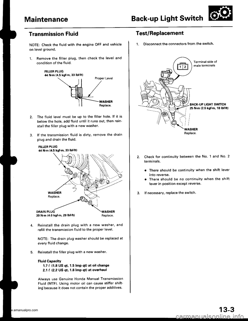
Transmission Fluid
NOTE: Check the fluid with the engine OFF and vehicle
on level ground.
1. Remove the filler plug. then check the level and
condition of the fluid.
FILLER PLUG44 N.m {4.5 kgf.m. 33 lbf ftl
ll
Ptopet Level
\--ril /
HllllllTl /
Hllllrlll /_rf-F{--rno."."
ll| | Replaco.
The fluid level must be up to the filler hole. lf it is
below the hole, add fluid until it runs out. then rein-
stall the tiller plug with a new washer.
lf the transmission fluid is diny, remove the drain
plug and drain the fluid.
FILLEB PLUGa,a N.m 14.5 kgf..n. 33 lbt'ftl
DRAIN PLUG39 N m (4.0 kgf.m, 29 lbf'ft)WASHERReplace.
Reinstall the drain plug with a new washer. and
refill the transmission fluid to the proper level.
NOTE: The drain plug washer should be replaced at
every fluid change.
Reinstall the filler plug with a new washer.
Fluid Capacity
1.7 / {1.8 US qt, 1.5 lmp qtl at oil change
2.1 ! 12.2 US qt, 1.A lmp qtl at overhaul
Alwavs use Genuine Honda Manual Transmission
Fluid (MTF). Using motor oil can cause stiffer shift-
ind because it does not contain the proper additives.
Test/Replacement
1. Disconnect the connectors from the switch.
Terminal side oImale lerminals
BACK.UP LIGHT SWTTCHr 25 N.m 12.5 kgt m, 18 lbf.ftl
WASHERReplace.
Check for continuity between the No. 1 and No. 2
terminals.
. There should be continuity when the shift lever
tnto reverse.
. There should be no continuity when the shift
lever in position except reverse,
lf necessary, replace the switch.
13-3
www.emanualpro.com
Page 516 of 1395
Gearshift Mechanism
Overhaul
Note these itemsl
. InsDect rubber parts for wear and damage when disassembling'
. Check that the new cotter pin is seated firmly.
. Be carelul not to damage the guide pipe when removing the cables'
CHANGE LEVER KNOS8 N.m (0.8 kgl.m, 5.8 lbf.ft)
SELECT CABLE
PLATESReplace.WASHEB
I curur(PlN I I
\II
\"1 a,?-@ -.4'
-(
I
\
6x9.8
Guide pipe in theDOOI,
COTTEF PIN
PLASTIC WASHERGUIDE PIPESSHIFT CABLE
'l.0 mmN.m {1.0 kgf.m, 7.2 lbf.ftl
(stLlcoNE
GREASEI
LEVER ASSEMBLY
8 x 1.25 mm13 N.m 11.3 kgt'm,9.4lbf ft)
FLOATINGCOLLAR
13-77
www.emanualpro.com
Page 672 of 1395

Symptom-to-Com ponent Chart
Hydraulic System (cont'd)
NOTES
See flushing procedure, page l4-264 and 265,
BSet idle rpm in gear to specified idle speed. lf still no good, adjust motor mounts as outlined in enginesection of this manual.
clf the large clutch piston O-ring is broken, inspect the piston groove for rough machining.
Dlf the clutch pack is seized or is excessively worn. inspect the other clutches fot wear, and check the orificecontrol valves, CPC valve, and linear solenoid for free movement.
lf the linear solenoid is stuck, inspect the clutches for wear.
lf the 1-2 shift valve is stuck closed. the transmission will not upshift. lf stuck open, the transmission hasno lst gear.
Hlf the 2nd orifice control valve is stuck, inspect the 2nd and 3rd clutch Dacks for wear.
lf the 3-4 orifice control valve is stuck, inspect the 3rd and 4th clutch packs for wear.
Jlf the clutch pressure control valve is stuck closed. the transmission will not shift out of lst gear.
Klmproper alignment of main valve body and torque converter housing may cause ATF pump seizure. Thesymptoms are mostly an rpm-related ticking noise or a high-pitched squeak.
Llf the ATF strainer is clogged with particles of steel or aluminum, inspect the ATF pump and differentialpinion shaft. lf both are OK and no cause for the contamination is found, replace the torque converter.
Mlf the lst clutch feed pipe guide in the end cover is scored by the mainshaft. inspect the ball bearing forexcessive movement in the transmission housing. lf oK, replace the end cover as it is dented. The o-rinounder the guide is probably worn.
N' Replace the mainshaft if the bushing for the 4th feed pipe is loose or damaged, lf the 4th feed pipe is darrFaged or out of round. replace the end cover.' Replace the mainshaft if the bushing for the l st feed pipe is loose or damaged. lf the 1st feed pipe is dam-aged or out of round, replace it.
oA worn or damaged sprag clutch is mostly a result of shifting the transmission in E!. E, or E positionwhile the wheels rotate in reverse. such as rocking the vehicle in snow.
PInspect the frame for collision damage.
lnspect for damage and wear:
l. Reverse selector gear teeth chamfers.
2. Engagement teeth chamfers of countershaft 4th and reverse gear.
3. Shift fork for scuff marks in center.
4. Differential pinion shaft for wear under pinion gears.
5. Bottom of 3rd clutch for swirl marks.
Replace items 1, 2, 3. and 4 if worn or damaged. lf transmission makes a clicking, grinding, or whirring noise,also replace mainshaft 4th gear, reverse idler gear, and countershaft 4th gear in addition to 1,2, 3, or 4.lf differential pinion shaft is worn, overhaul differential assembly, replace ATF strainer, and thoroughly cjeantransmission, flush torque converter. cooler, and lines,lf bottom of 3rd clutch is swirled and transmission makes gear noise. replace the countershaft and final drivenoear,
Be very careful not to damage the torque converter housing when replacing the main ball bearing. you
may also damage the ATF pump when you torque down the main valve body. This will result in ATF pumpseizure if not detected. Use the Drooer tools.
SInstall the main seal flush with the torque converter housing. lf you push it into the torque converterhousing until it bottoms out, it will block the fluid return passage and result in damage.
www.emanualpro.com
Page 848 of 1395

Component Locations
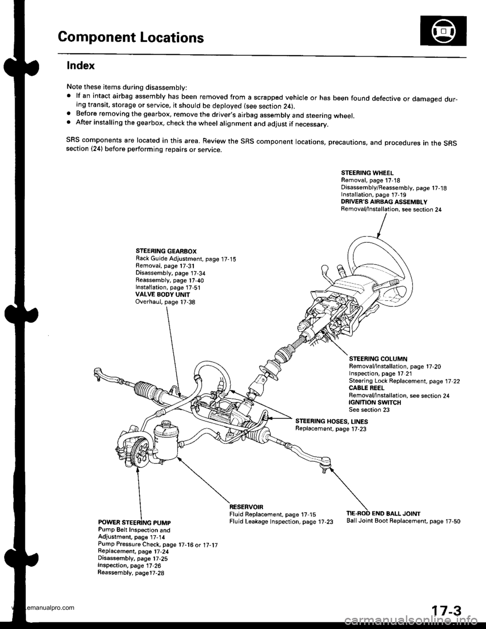
lndex
Note these items during disassembly:' lf an intact airbag assembly has been removed from a scrapped vehicle or has been found defective or damaged dur-ing transit, storage or service. it should be deployed (see section 24),a Before removing the gearbox, remove the driver.s airbag assembly and steering wheel.. After installing the gearbox, check the wheel alignment and adjust if necessary.
SRS components are located in this area. Review the SRS component locations, precautions, and procedures an the SRssection (24) before performing repairs or servrce.
STEERING WHEELRemoval, page 17,18Disassembly/Reassembly, page 1?,18Installation, page 17-19DRIVER'S AIRBAG ASSEMBLYRemoval/lnstallation, see section 24
STEERING GEARBOXRack Guide Adjustment, page 17-15Removal, page 17-31Disassembly, page 17-34Reassembly, page 17,40Installation, page 17,51VALVE BODY UNITOverhaul, page 17-38
STEERING COLUMNRemoval/lnstallation. page 17-20Inspection, page l7 21Steering Lock Replacement, page 17 22CABLE REELRemoval/lnstallation, see section 24tcNrnoN swtTcHSee s€ction 23
STEERING HOSES, LINESReplacement. page l7-23
Pump Belt Inspection andAdjustment, pag€ t7-14Pump Pressure Check, page 17-16 ot 17-1jReplacemont, page 17-24Disassembly, pa96 17,25Inspection, page 17-26Reassembly. page17-28
RESERVOIRFluid R6placement. page 17 15Fluid Leakage lnspection, page 17-23
END BALL JOINTBallJoint Boot Replacement, page 17-50
17-3
www.emanualpro.com
Page 1091 of 1395

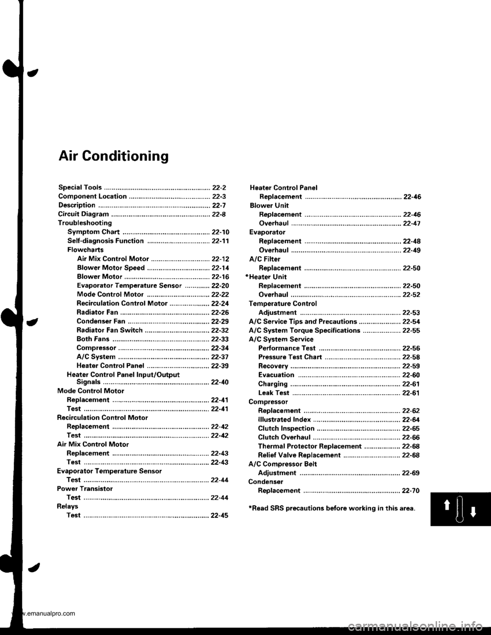
Air Conditioning
Heater Control Panel
Reofacement ,.,...,,.,..,.,.,,22-46
Blower Unit
Replacement .................. 22-46
Overhaul ...........,,,., .......-.22-17
Evaporalor
ReDlacement ...,.,.,..,......,22-4A
Overhaul ................ .........22-19
A/C Filter
Replacement ..................22-50*Heater Unit
ReDfacement ..................22-50
Overhaul ..,.,..,.,...,.. .........22-52
Temperature Control
Adiustment ....................22-53
A/C Service Tips and Precauiions............-....-.... 22-54
A/C System Torque Specifications .................... 22-55
A/C System Service
Performance Test ......,...22-56
Pressure Test Chart .-.....22-5a
Recovery ..............,. ...-.-...22-59
Evacuation -...........-........22-60
Charging ................ .......-.22-61
Leak Test ........................22-61
Compressor
Repfacement ..........-.......22-62
flfustrated Index .....,.......22-64
Cfutch fnspection .........,.22-65
Cfutch Overhaul ............- 22-66
Thermaf Protector Rep|acement ................... 22-68
Refief Valve Replacement .............................. 22-68
A/C Comoressor Belt
Adiustment .................... 22-69
Condenser
Repfacement .,.....,,.,..,.,..22-70
'Read SRS precautions betore working in this area.
www.emanualpro.com
Page 1093 of 1395
Component Location
lndex
EVAPORATORReplacement, page 22-48Overhaul, page 22-49
SERVICE VALVEILOW-PRESSURE SIDE}
CONDENSERReplacement, page 22-70
A/C PRESSURE SWTTCHWhen the refrigorant pressure is below 200 kPa 12.0 kglc.r|r,28 psi) or abov€ 3,200 kPa (32 kgflcmr, 455 psi), the AJC pressureswitch opens the circuit to the Ay'C switch and stops the airconditioning to protect the compressor.
Replacement, page 22-62Clutch Inspection, page 22-65Clutch Overhaul, pago 22-66Thermal Protector Replacement, page 22-68Relief Valve Replacem€nt. page 22-68
SERVICE VALVEIHIGH-PRESSURE SIDEI
,
[\,
-il
(cont'd)
www.emanualpro.com