Page 103 of 1395

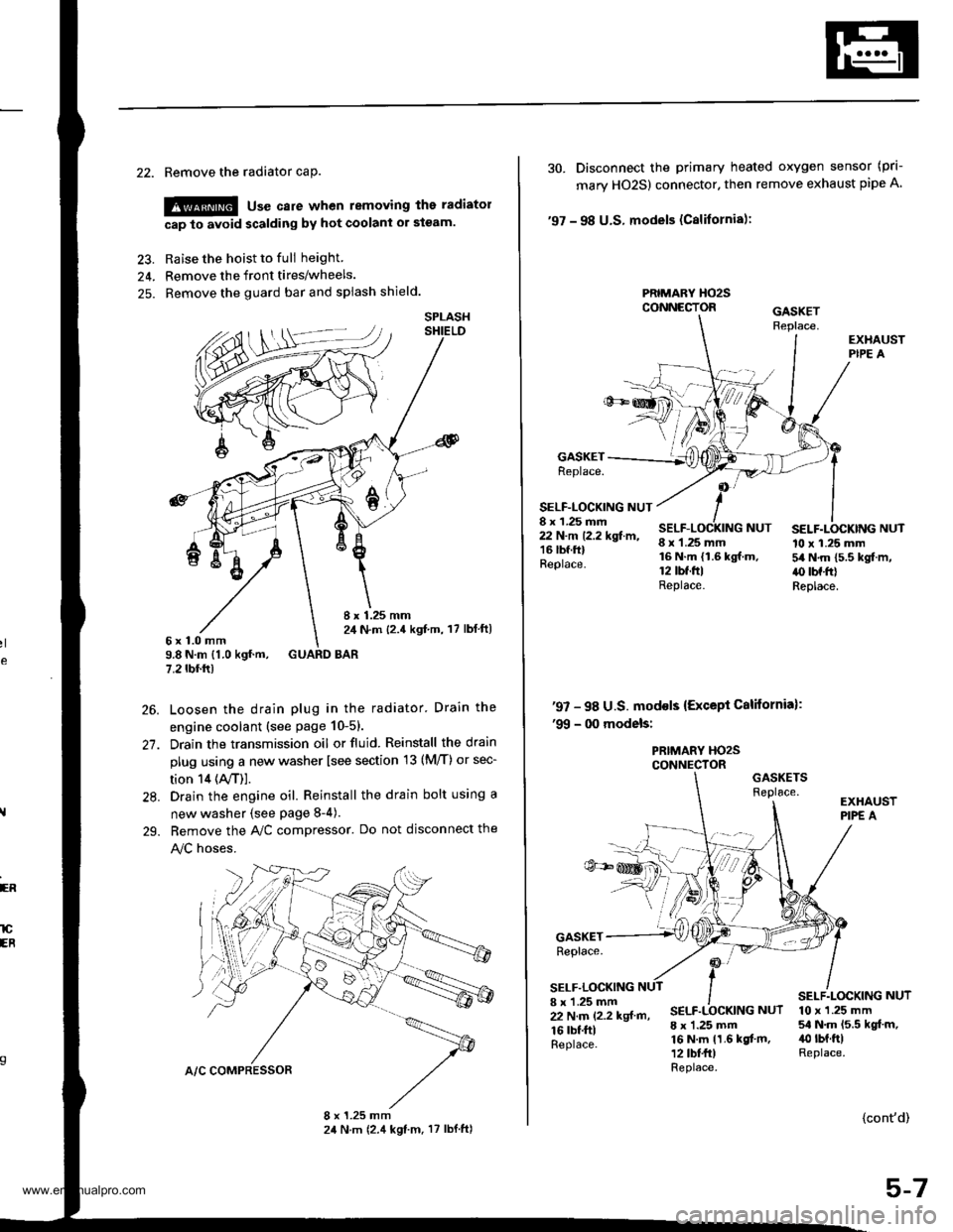
22. Remove the radiator caP.
!@ use care when removing the radiatol
cap to avoid scalding by hot coolani or steam.
23. Raise the hoist to full height
24. Remove the front tires/wheels.
25. Remove the guard bar and splash shield.
8 x 1.25 mm2,1 N.m {2.4 kgf,m, 17 lbl ft)6x1.0mm9.8 N.m {1.0 kgf.m, GUARD BAR7.2 tbf.rr)
Loosen the drain plug in the radiator. Drain the
engine coolant (see page 10-51.
Drain the transmission oil or fluid. Reinstall the drain
plug using a new washer lsee section 13 (M/T) or sec-
tion 14 (ly'T)].
Drain the engine oil. Reinstall the drain bolt using a
new washer {see page 8-4).
Bemove the A,/C compressor. Do not disconnect the
!y'C hoses.
SPLASH
26.
27.
28.
29.
ER
lCEB
30. Disconnect the primary heated oxygen sensor (prl-
mary HO2S) connector. then remove exhaust pipe A
'97 - 98 U.S. models (Cslifornia):
PRIMARY HO2SCONNECTOR
GASKETReplace.
SELF-LOCKING NUT8 x 1.25 mm22 N.m 12.2 kgf.m,16 lbf.ftlReplace.
8 x 1.25 mm16 N.m {1.6 kgf.m.12 tbt.ftlReplace.
SELF.LOCKING NUT10 x 1.25 mm54 N.m 15.5 kgf.m,.() tbf.frlReplace.
NUT
'97 - 98 U.S. mod€ls {Except California):'99 - 00 models:
PRIMARY HO2SCONNECTORGASKETSReplace.
GASKETReplace.
SELF.LOCKING8 x 'l.25 mm22 N.m (2.2 kgf m,
16 rbf.ftlReplace.
SELF.LOCKING NUT
8 x 1.25 mm16 N.m 11.6 kgf.m,12 tbt fr)Replace.
10 x 1.25 mm54 N.m 15.5 kgt.m,40 rbt.ftlReplace.
{cont'd)
5-7
www.emanualpro.com
Page 681 of 1395
Transfer Assembly
Removal
@ Make sure the lifts, iacks, and safety
stands are placed properly (see section 11.
1. Raise the front of the vehicle, and make sure it is
supported securely.
2. Set the parking brake, and block both rear wheels
securelv.
3 Drain the automatic transmission fluid (ATF).
Reinstall the drain plug with a new sealing washer'
DRAIN PLUG'18 x'1.5 rnm49 N.m 15.0 kgf.m, 36 lbl.ftl
4. Remove the guard bar and the splash shield.
GUARD 8AR
14-165
5.Disconnect the primary heated oxygen sensor
{Primary HO2S) connector.
Remove exhaust pipe A.
SELF-LOCKINGNUTBeplace.
7.
SEI-F.LOCKINGNUTReplace.
NUTReplace
Remove the shift cable cover.
Remove the snap pin and control pin, then separate
the shift cable from the control lever. Do not bend
the shift cable excessively.
(cont'd)
www.emanualpro.com
Page 1054 of 1395
A>, 5 V.2
>: Clip locationsA>, 5 B>.3
lf necessary, remove the front bumper beam, front bumper upper beam and guard bar.
>: Boh locationsc>.6D>,2E>,6
TIE DOWNHOOK
Yl- r
{to/
Installation is the reverse ot the removal procedure.
NOTE:
. Make sure the front bumper engages the front
bumper upper beam securely.
. It necessary, adjust the front bumper upper beam
to obtain the proper gap.
. lf necessary, replace any damaged clips.
Gfu @p;i,li',ll-"-'
TIE.DOWNHOOK
v1
10 x 1.25 mm38 N.rn {3.9 kgf.m,28 rbl.ftl
@,,2
nln-nlznr I
dE6 I #\Er+ | ;lHl= |€ =.=r t:Wl
BEAM
FRONT BUMPEB
20-73
www.emanualpro.com