1999 HONDA CR-V Bolt
[x] Cancel search: BoltPage 1307 of 1395
Inspection
SRS components ale located in this area. Review the
SRS component locations, precautions, and procedures
in this section (24) before preforming repairs or service
('98 - 00 models).
!!!@ To avoid accidontal deployment and possi-
6i6-'rnpry. att"ays aisconnsct th€ seat beh tensioner con-
n€ctor belore removing tho retrastor {.98 - 00 modols, seo
page2+231.
Rgtlastor Insgection
1. Before installing the retactor, check that the seat belt
can be pulled out freely
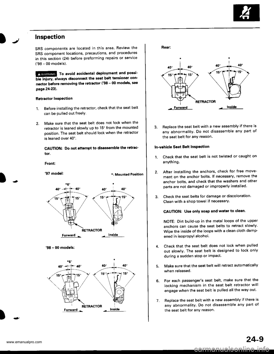
2. Make sure that the seat belt does not lock when the
retractor is leaned slowly up to 15'from the mounted
Dosition. The seat belt should lock when the retractor
is leaned over 40".
CAUTION: Do not attsmpt to dbassemble ths relrac'
tor.
Front:
'97 modol:.: Mounted Position
RETRACTOR
Forward -
'98 - 00 modcls:
lnside
RETRACTOR
)
Forward -
'1.
24-9
Rear:
RETRACTOR
Forwerd lnsida
3. Beplace the seat belt with a new assembly if there is
any abnormality. Do not disassemble any part of
the seat belt for any reason.
In-vehicle S68t Belt InsPestion
1. Ch€ck that the seat belt is not twisted or caught on
anything.
40.
/A
\|_t-.
*1ix
\/
Lls=
Forwerd
After installing the anchors, check for free move-
ment on the anchor bolts lf necessary, remove the
anchor bolts, and check that the washers and other
parts are not damaged or improperly installed.
Check the seat belts for damage or discoloration.
Clean with a shop towel if necessary.
CAUTION: Uso only soap and wator to clean.
NOTE: Dirt build-up in the metal loops of the upper
anchors can cause the seat belts to retract slowly
Wipe the inside of the loops with a clean cloth damP
ened in isopropyl alcohol.
Check that the seat belt does not lock when pulled
out slowlv. The seat belt is designed to lock only
during a sudden stop or impact.
Make sure that the seat belt will retract automatically
when released.
For each passenger's seat belt, make sure that the
locking mechanism in the seat belt retractor will
engage when the seat belt is pulled all the way out.
Replace the seat belt with a new assembly if there is
any abnormality. Do not disassemble any part of
the seat belt for any reason.
www.emanualpro.com
Page 1314 of 1395
Description
J)
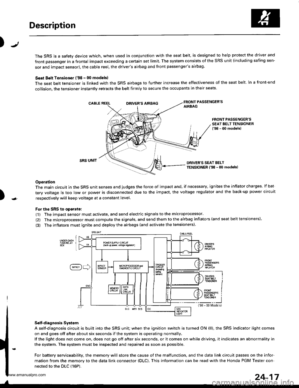
The SRS is a safety device which, when used in conjunction with the seat belt, is designed to help protect the driver and
front passenger in a frontal impact exceeding a certain set limit. The system consists of the SRS unit (including safing sen-
sor and impact sensor), the cable reel, the driver's airbag and front passenger's airbag.
Seat Bolt Tensioner {'98 - 00 models}
The seat belt tensioner is linked with the SRS airbags to further increase the effectiveness of the seat belt. In a front-end
collision, the tensioner instantly retracts the belt firmly to secure the occupants in their seats
FRONT PASSENGER'SAIREAGDRIVER'S AIRBAG
FRONT PASSENGER'SSEAT BELT TENSIONER{'98 - 00 modelsl
)
SRS UNITDRIVER'S SEAT BELTTENSIONER l'98 - 0O modeb)
Operation
The main circuit in the SRS unit senses and judges the force of impact and, if necessary, ignites the intlator charges. lf bat
tery voltage is too low or power is disconnected due to the impact, the voltage regulator and the back-up power circuit
respectively will keep voltage at a constant level.
For the SRS to operate:
(1) The impact sensor must activate, and send electric signals to the microprocessor.
(2) The microprocessor must compute the signals, and send them to the airbag inflators (and seat belt tensioners).
(3) The inflators must ignite and deploy the airbags (and activate the tensioners).
Selt-diagnosis System
A self-diagnosis circuit is built into the SRS uniU when the ignition switch is turned ON (ll), the SRS indicator Iight comes
on and goes off after about six seconds if the system is operating normally.
lf the light does not come on, does not go off after six seconds, or it comes on while driving, it indicates an abnormality in
the system. The system must be inspected and repaired as soon as possible.
For battery serviceability, the memory will store the cause of the malfunction, and the data link circuit passes on the infor
mation from the memory to the data link connector (DLC). This information can be read with the Honda PGM Tester con-
nected to the DLC {16P).
198
---__-l
TENSTO1En II
_-___J- 00 N4ode s)
24-17
www.emanualpro.com
Page 1365 of 1395
Troubleshooting
DTC 3-3
CAUTION; Whenever the ignition switch is ON llll, or
has b€on turned OFF for l6ss than three minutes, be
carelul not to bump the SRS unit; the airbags could
accidontally deploy and cause damage or iniuries.
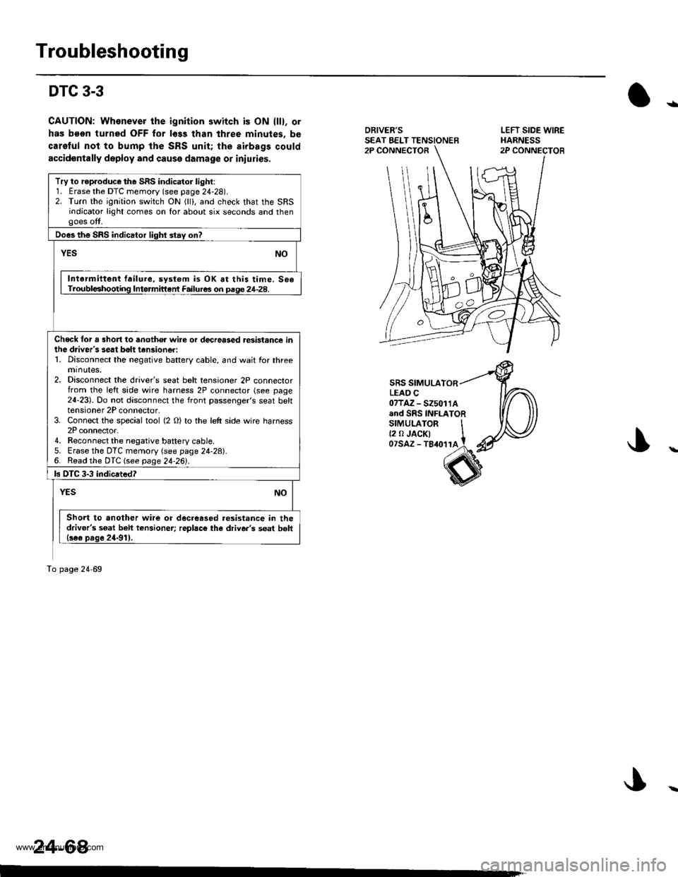
ORIVER'SSEAT EELT TENSIONER2P CONNECTOR
SRS SIMULATORLEAO C07TAZ-525011Aand SRS INFLATORsrMULAroR It2 0 JACK| tozsAz - ls{orra !
s
Try to r€produce the SRS indicator light:1. Erase the DTC memory (see page 24-28).2. Turn the ignition switch ON (lll, and check that the SRSindicator light comes on for about six seconds and thengoes off.
Does the SRS indicator lighl stay on?
YESNO
Intarmittent failure, system is OK at this time. 506Troubl€shooting Intormittant Failures on paqe 24-28.
Check tor a 3hort to anoth€r wire or decreased resistance inihe driver's seat bolt tan3ioneri1. Disconnect the negative battery cable, and wait for threeminutes,2. Disconnect the driver's seat belt tensioner 2P connectorfrom the left side wire harness 2P connector (see page24-23). Do not disconnect the front passenger's seat belttensioner 2P connector,3. Connect the special tool (2 O) to the left side wire harness2P connector.4. Reconnect the negative battery cable5. Erase the DTC memory (see page 24-28).6. Read the DTC (see page 24.26l'.
ls DTC 3-3 indicated?
NOYES
Short to another wire or decreased.esistance in thedriver's s6at beh tcnsioner; replac€ the diive.'s seat bolt{se€ prge 24-911.
To page 24 69
24-64
LEFT SIDE WIREHARNESS2P CONNECTOB
ra
www.emanualpro.com
Page 1370 of 1395
)
LEFT SIDE wlREHARNESS2P CONNECTOR
SRS MAINHARNESS
(
C
00
2P CONNECTOR
SRS SIMULATORLEAD C07TAZ - SZ5011Aand SRS INFLATORSIMULATOR
/ (2 o JACK)
/ 07sAz - TB4o11A
I
)
SRS MAIN HABNESS18P CONNECTOR
)
Frcm page24-12
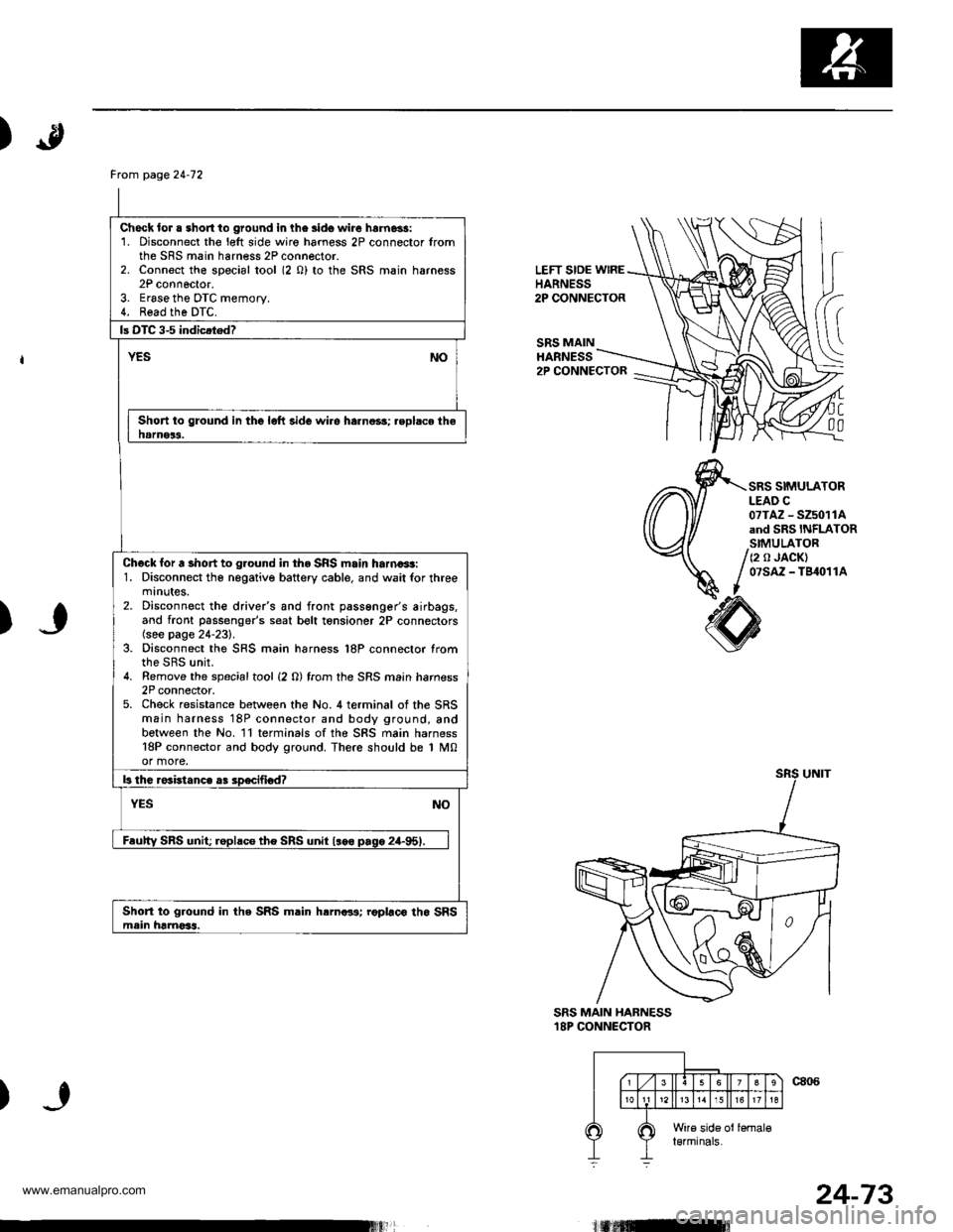
Check lor . short to ground in lhe lido wire hrrnassi1. Disconnect the l€lt side wiro hamess 2P connector fromthe SRS main harness 2P connector.2. Connect the special tool (2 0) to the SRS main harness2P connoctor.3. Erase the DTC memory.4. Read the DTC.
Short to ground in the lolt side wi.e harno3s; .eplsce thehamer3.
Check for a short to ground in tho SRS main harna+t:1. Disconnect tho negative battery cable, and wait for threemtnutes.2. Disconnect the drive/s and front passenger's airbags,and front passenger's seat bolt tensioner 2P connectors(see page 24-231.3. Disconnect the SRS main harness l8P connector fromthe SRS unit.4. Remove the spacialtool {2 0) from the SRS main hamess2P connector,5. Check resistance between the No. 4 terminal of the SRSmain harness 18P connector and body ground, andbetween the No. ll terminals ofthe SRS main harness18P connector and body ground. There should be 1 M0or more.
Short to ground in the SRS m.in hrrnar3; roplaco tho SRSmein hamoSs.
24-73
www.emanualpro.com
Page 1371 of 1395
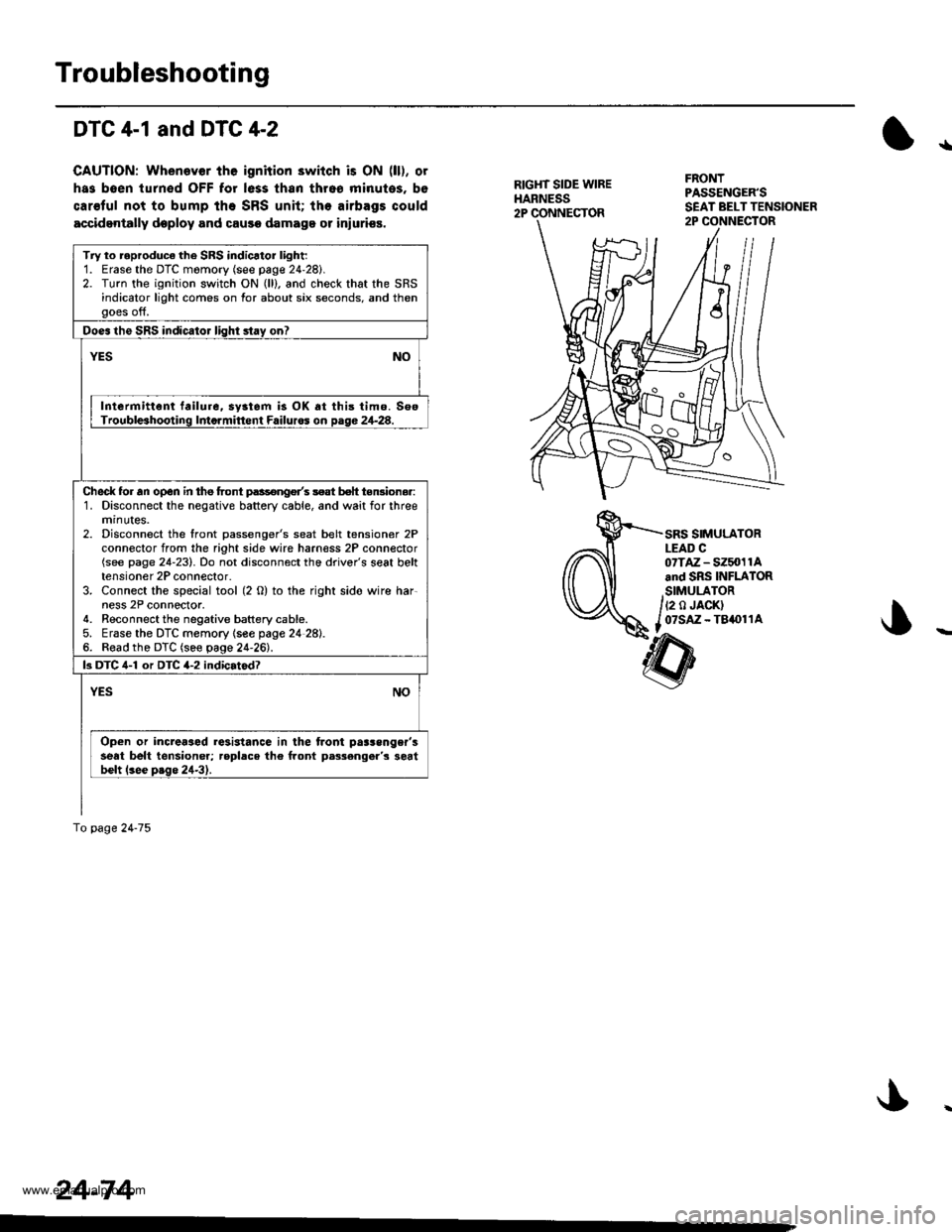
Troubleshooting
DTC 4-1 and DTC 4-2
CAUTION: Whenever tho ignition 3witch is ON (ll), ot
has boen turn€d OFF for less than thro6 minutos, bo
car€ful not to bump ihe SRS unit; the airbags could
accidentally deploy and causo damage or iniurios,
!|
RIGH1 SIDE WIREHARNESS2P CONNECTOR
FRONTPASSENGER'S
Try to roproduca the SRS indicator light:1. Erase the DTC momory (see page 24'28i.2. Turn the ignition switch ON (ll). and check that the SRSindicator light comes on for about six seconds. and thenooes off,
Does the SRS indicator lisht stay on?
YESNO
Intermittent failure, syatem i3 OK at this tim6. SooTrouble3hooting Inta.mittent Failuros on page 24-28.
Ched( for an open in the front p.ssongo/s 3eat bolt teruiona.:1. Disconnect the negative battery cable, and wait for threemrnutes.2. Disconnect the front passenger's seat belt tensioner 2Pconnector from the right side wire harn€ss 2P conneclor(see page 24-23). Do not disconnect the driver's seat belttensioner 2P connector.3. Connect the special tool (2 O) to the right sido wire har-ness 2P connector.4. Reconnect the negative battery cable.5. Erase the DTC memory lsee page 24 28).6. Read the DTC (see page 24'26).
k DTC 4-1 or DTC 4-2 indicatodT
YESNO
Open or increaaad resistance in lhe tront pa$enger'sseat belt tensioner; roplace the front p.s3engar's 3eatbelt lsee p.ge 24-31.
fo page24-75
24-74
SRS SIMULATORLEAD C07TAZ - SZ5n11Aand SRs INFLATORSIMULATOR
/iz o.ncri
f ozsAz - T8.011Ao
www.emanualpro.com
Page 1384 of 1395
Driver's Airbag
1.
Replacement
After a collision in which the airbags were deployed, the
airbags, the seat belt tensioners (if so equipped), and
the SRS unit must be replaced.
@ Store a removed airbag with the pad su.-
tacs up, lf th€ airbag is improperly stored face down.
accidental deployment could propal the unit with
enough forc€ io causg serioug iniury.
CAUTION:
. Always disconnoct the drivor's airbag connector
when the SRS main harness is disconnactod.
. Do not disassemble or tamper with ihe airbag.
NOTE:
Do not install used SRS parts from another vehicle,
When repairing, use only new SRS parts.
Carefully inspect the airbag before you install it. Do
not install an airbag that shows signs of being
dropped or improperly handled, such as dents, cracks
or deformation.
Disconnect the battery negative cable, then discon-
nect the positive cable from the battery, and wait at
least three minutes.
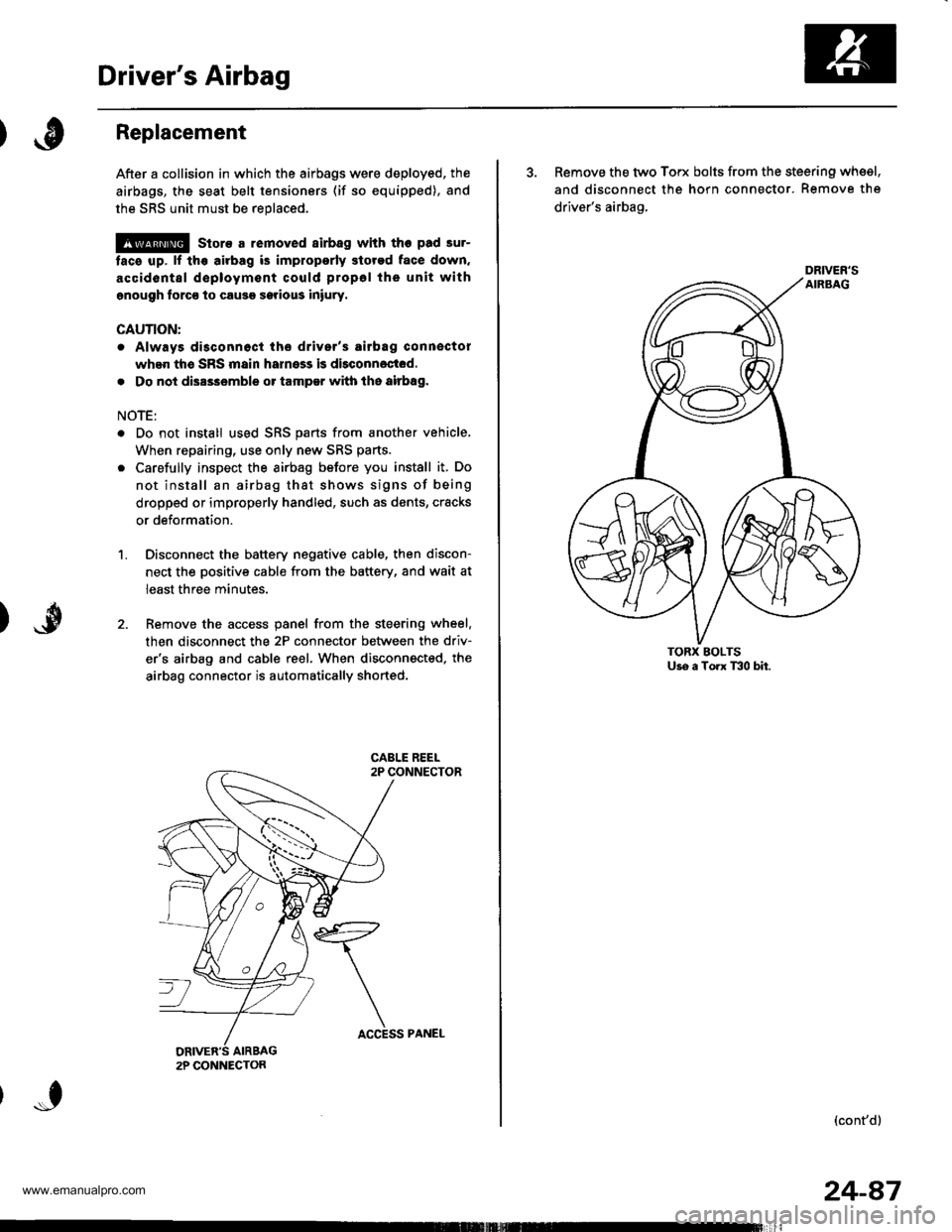
Remove the access panel from the steering wheel.
then disconnect the 2P connector between the driv-
er'6 airbag and cable reel. When disconnected. the
airbag connector is automatically shorted.
2P CONNECTON
ACCESS PANEL
24-87
3. Remove the two Torx bolts from the steering whsel,
and disconnect the horn connector. Remove the
driver's airbag,
(cont'd)
DRIVER'S
www.emanualpro.com
Page 1385 of 1395
Driver's Airbag
Replacement lcont'd)
CAUTION: 8. sure to instattthe SRS wiring so that it isnot plnched or inlerfsring with other parts.
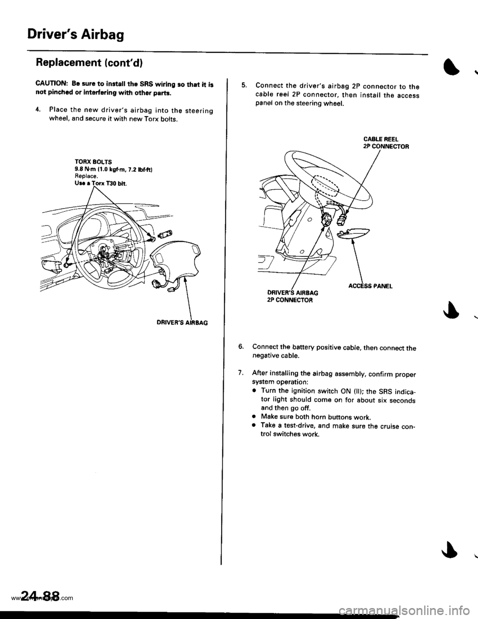
4. Place the new driver's airbag into the steeringwheel, and secure it with new Torx bolts.
TORX EOLTS9.8 N,m 11.0 kgl.m, 7.2 tbf,ftlFeplace.
24-88,
5. Connect the driver's airbsg 2p connector to thecable reel 2P connector, then install the accesspanel on the steering wheel.
Connect the battery positive cable. then connect thenegative cable.
After installing the airbag assembly, confirm proper
system operation:
. Turn the ignition switch ON llt); the SRS indica-tor light should come on for about six secondsand then go off.. Mske sure both horn buttons work.o Take a test-drive, and make sure the cruise con-trol switches work.
7.
2P CONNECTOR
www.emanualpro.com
Page 1388 of 1395
Cable Reel
)Replacement
@ stors a removed airbag with the pad sur-
tace up. lf th€ airbag is improperly stored face down,
accidental d6ployment could propel the unit withgnough force to cause serious iniuty.
CAUTION:
. Always disconnect the airbag connector whgn the
SRS msin harness is disconnoctod.
. Do not disassemblo or tamper with the airbag.
NOTE: Carefully inspect the airbag before installing it.
Do not install an airbag that shows signs of being
dropped or improperly handled, such as dents, cracks or
deformation,
'1.Disconnect the battery negative cable, then discon-
nect the positive cable from the battery, and wait at
least three minutes.
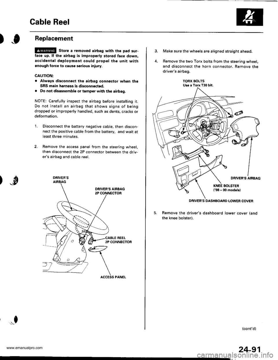
Remove the access panel from the steering wheel,
then disconnect the 2P connector between the driv-
er's airbag and cable reel.
*f
DRIVER'S
24-91
Make sure the wheels are aligned straight ahead.
Remove the two Torx bolts from the steering wheel,
and disconnect the horn connector, Remove the
driver's airbag,
TORX BOLTSUse a Torx T30 bit.
5. Remove the driver's dashboard lower cover (and
the knee bolster).
(cont'd)
DRIVER'S DASHBOARD LOWER COVER
www.emanualpro.com