Page 862 of 1395
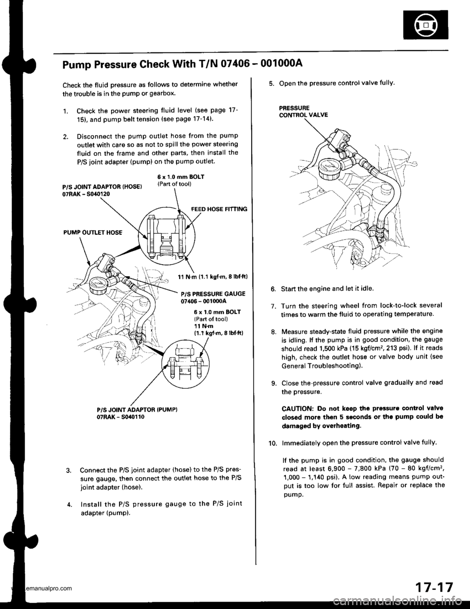
Pump Pressure Check With T/N 07406 -
Check the fluid pressure as follows to determine whether
the trouble is in the pump or gearbox.
1. Check the power steering tluid level (see page 17-
151, and pump belt tension (see page 17-14).
2. Disconnect the pump outlet hose from the pump
outlet with care so as not to spill the power steering
fluid on the frame and other parts, then install the
P/S joint adapter (pump) on the pump outlet.
6 x 1.0 mm BOLT(Part oftool)
FEED HOSE HfNNG
PUMP OUTLET HOSE
1'l N.m 11.1 kgf.m,8lbf ft)
P/S PRESSURE GAUGE07406 - 001000A
6 x 1.0 mm BOLT(Part ol tool)11 N.m(1.r kg{.m,8lbf'ft|
Connect the P/S joint adapter (hose) to the P/S pres-
sure gauge, then connect the outlet hose to the P/S
joint adapter (hose).
Install the P/S pressure gauge to the P/S joint
adapter (pumpl.
001000A
5. Open the pressure controlvalve fully.
PRESSURECONTROL VALVE
7.
10.
Start the engine and let it idle.
Turn the steering wheel from lock-to-lock several
times to warm the tluid to operating temperature.
Measure steady-state fluid pressure while the engine
is idling. It the pump is in good condition, the gauge
should read 1,500 kPa (15 koflcm'�,213 psi). lf it reads
high. check the outlet hose or valve body unit {see
General Troubleshooting),
Close the-pressure control valve gradually and read
the oressure.
CAUTION: Do not keep the pressurs control valve
closed more then 5 seconds or the pump could bo
damaged by overheating.
lmmediately open the pressure controlvalve fully.
lf the pump is in good condition, the gauge should
read at least 6,900 - 7;800 kPa (70 - 80 kgflcm'�,
1,000 - 1.140 psi), A low reading means pump out-
Dut is too low for {ull assist. Repair or replace the
oumo.
17-17
www.emanualpro.com
Page 868 of 1395

Power Steering Hoses, Lines
Fluid Leakage Inspection
HOSES and LINES
. lnspect hoses for damage. leaks. interference and twisting
. Inspect fluid linesfor damage, rusting and leakage.
. Check for leaks at hose and line joints and connections.
FEED HOSE37 N.m 13.8 kgf.m, 27 lbtft)RETURN LINE JOINT28 N.m (2.9 kgf.m.21 lbf.ftl
CYLINDER LINES17 N.m (1.7 kgf.m. 12 lbf.ftl
FOWER STEERING PRESSURE SWITCH12 N.m (1.2 kgf.m,8.7 lbtft)
26 N.m (2.7 kgf.m, 20 lbf.ft)
GEARBOX .nd VALVE BODY UNllCheck for leaks at the mating surfaceand flare nut connections.
CYLINDER
FEED HOSE11 N.m('1.1 kgt.m, 8 lbf.ftl
SUCTION HOSE
PUMP ASSEMBLYCheck for leaks atthe pump
seal. inlet and outlet fittings.
Note these items during installation:
. Connect each hose to the corresponding line securely
until it contacts the stop on the line. Install the clamp
or adjustable clamp at the specified distance from the
hose end as shown.
. Check all clamDs for deterioration or deformation;
replace with the clamps new ones if necessary.
. Add the recommended power steering fluid to the
specified level on the reservoir and check for leaks.
ADJUSTABLE HOSE CLAMP: la)
. Position the adjustable hose clamps at the points
indicated by (a) in the drawing above.
. Slide the hose over the line until it contacts the stop.
HOSE CLAMP: lbl
. Position the hose clamps at the
(b) in the drawing above.
. Slide the hose over the line until
Replacement
10.01 - 0.22 in)
points indicatsd by
it contacts the stop,
2.0 - 4.0 mm10.08 - 0.16 inl2.5 - 5.5 mm{0.01 - 0.22 in}17 -23
www.emanualpro.com
Page 876 of 1395
Power Steering Gearbox
Removal
Note these items during removal:
. Using solvent and a brush, wash any oil and dirt off
the valve body unit its lines, and the end if the gear-
box. Blow dry with compressed air.
. Be sure to remove the steering wheel before discon-
necting the steering joint. Damage to the cable reel
can occur.
. With 4WD. tilt the engine with a jack to expand the
clearance between the transfer assembly and rear
beam when removing the steering gearbox from the
rear oeam.
Do not remove the steering gearbox by removing the
transfer assembly from the transmission.
1. Drain the power steering fluid as described on page'17-15.
Raise the vehicle, and suppon it on safety stands in
the proper locations (see section 1).
Remove the front wheels,
Remove the drive/s airbag assembly {see section 24).
Remove the steering wheel {see page 17-18).
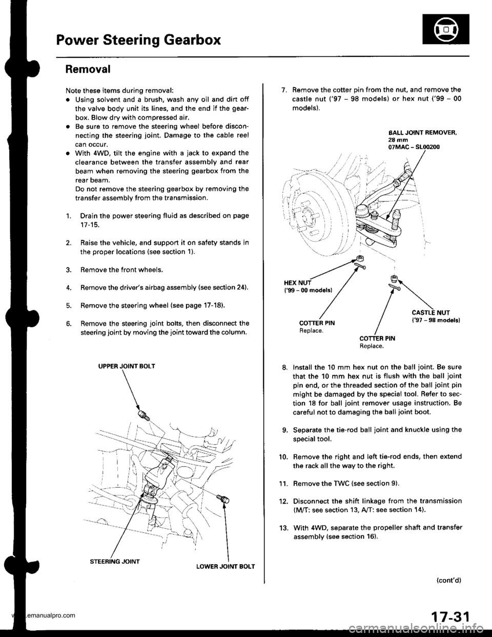
Remove the steering joint bolts, then disconnect the
steering joint by moving the joint toward the column.
UPPER JOINT BOLT
LOWER JOINT BOLT
13.
7. Remove the cotter pin from the nut, and remove the
castle nut {'97 - 98 models) or hex nut ('99 - 00
models).
COTTER PINReplace.
Install the 10 mm hex nut on the ball joint. Be sure
that the 10 mm hex nut is flush with the ball joint
pin end, or the threaded section of the ball joint pin
might be damaged by the special tool. Refer to sec-
tion 18 for ball joint remover usage instruction, Be
careful not to damaging the ball joint boot.
Separate the tie-rod ball joint and knuckle using the
special tool.
Remove the right and left tie-rod ends, then extend
the rack all the way to the right.
Remove the TWC (see section 9).
Disconnect the shift linkage from the transmission
(M/T: see section 13, A/T: see section 14).
With 4WD. separate the propeller shaft and transfer
assembly (see section 161.
10.
11.
(cont'd)
17-31
www.emanualpro.com
Page 877 of 1395
Power Steering Gearbox
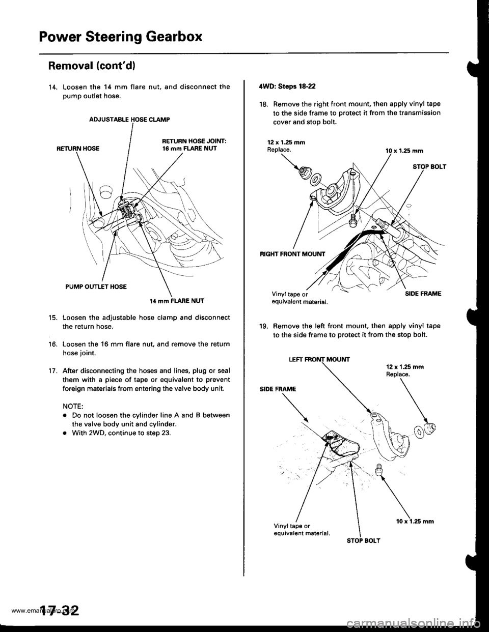
AN'USTABLE HOSE CLAMP
Removal (cont'dl
14. Loosen the 14 mm flare
pump outlet hose.
nut, and disconnect the
14 mm FLARE NUT
15. Loosen the adjustable hose clamp and disconnect
the return hose,
16. Loosen the 16 mm flare nut, and remove the return
hose joint.
17. After disconnecting the hoses and lines, plug or seal
them with a piece of tape or equivalent to prevent
foreign maisrials from entering the valve body unit.
NOTE:
. Do not loosen the cylinder line A and B between
the valve body unit and cylinder.
. With 2WD, continue to step 23.
17 -32
STOP BOLT
10 x 1.25 mm
4WD: Stepr 18-22
18. Removethe right tront mount, then apply vinyl tape
to the side frame to protect it from the transmission
cover and stop bolt.
12 x 1.25 fiiAReplace.
RIGHT FRONT MOUNT
x 1,25 mm
SIDE FRAME
'19. Remove the left front mount, then apply vinyl tape
to the side frame to protect it from the stop bolt.
Vinyltape orequivalgnt material.
Vinyltap€ orequival€nt m6terial.
www.emanualpro.com
Page 879 of 1395
Power Steering Gearbox
Removal (cont'dl
24. Remove the mounting brackets.
25.lvlove the steering gearbox to the right so the
rack end clears the rear beam, then place the
rack end below the rear beam.
left
left
Move the steering gearbox to the left, and tilt the
left side down to remove it.
With 4WD. remove the steering gearbox through
the clearance between the transfer assembly and
propeller shaft.
MOUNTING BRACKETS
STEEBING GEARBOX
17 -34
4. Pull the boots away from the ends of the gearbox.
Disassembly
Steering Rack Disassembly
Note these items when disassembling:
. Before disassembling the gearbox, wash it off with
solvent and a brush.
. Do not dip seals and O-rings in solvent.
1. Remove the steering gearbox (see page 17-31).
2. Remove airtube and clips.
3. Remove the boot bands and tie-clips.
AIR TUBE
www.emanualpro.com
Page 880 of 1395
5. Hold the steering rack with a wrench {'98 - 00 mod-
els: left end onlv), and unscrew the rack end with
another wrench, Be careful not to damage the rack
surface with the wrench,
LOCK WASHER
Loosen the locknut, then remove the rack guide
screw and O-ring ('97 model).
6.
1.
LOCKNUT
Remove the spring and the rack guide from the gear-
DOX.
RACK GUIDE
9.
8. Remove cylinder lines A and B from the gearbox,
CYLINDER LINE A
Drain the fluid from the cylinder fittings by slowly
moving the steering rack back and {orth.
Remove the two tlange bolts, then remove the valve
body unit from the gearbox. (See page 17-38 for
valve body unit disassembly.)
VINYL TAPE
FLANGE BOLT
Apply vinyl tape to stepped portion of the pinion
shaft, and remove the dust cover.(cont'd)
DUST COVER
11.
17-35
www.emanualpro.com
Page 881 of 1395
Power Steering Gearbox
Disassembly {cont'd}
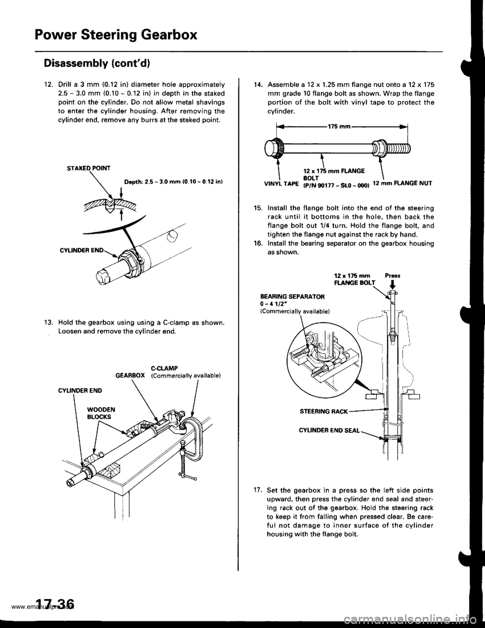
12. Drill a 3 mm (0.12 in) diameter hole approximately
2.5 - 3.0 mm (0.10 - 0.12 in) in depth in the staked
point on the cylinder. Do not allow metal shavings
to enter the cylinder housing. After removing the
cylinder end, remove any burrs at the staked point.
D.oth: 2.5 - 3.0 mm 10.10 - 0.12 inl
CYUNOER
Hold the gearbox using using a C-clamp as shown,
Loosen and remove the cvlinder end.
13.
17-36
14, Assemble a 12 x 1.25 mm flange nut onto a '12 x 175
mm grade 10 flange bolt as shown, Wrap the flange
portion of the bolt with vinyl tape to protect the
cvlinder,
VINYL TAP€ tp/N 90177 - SLO - OOOI 12mmFLANGENUT
Install the flange bolt into the end of the steering
rack until it bottoms in the hole. then back the
flange bolt out 1/4 turn. Hold the flange bolt, and
tighten the flange nut against the rack by hand.
Install the bearing separator on the gearbox housing
as snown.
15.
BEARING SEPARATOR0 - 1112'(Commercially available)
17.
STEERING RACK
CYLINDER €ND
Set the gearbox in a press so the lelt side points
upward, then press the cylinder end seal and steer-
ing rack out of the gearbox. Hold the steering rack
to keep it from falling when pressed clear. Be care-
ful not damage to inner surface of the cylinder
housing with the flange bolt.
www.emanualpro.com
Page 882 of 1395
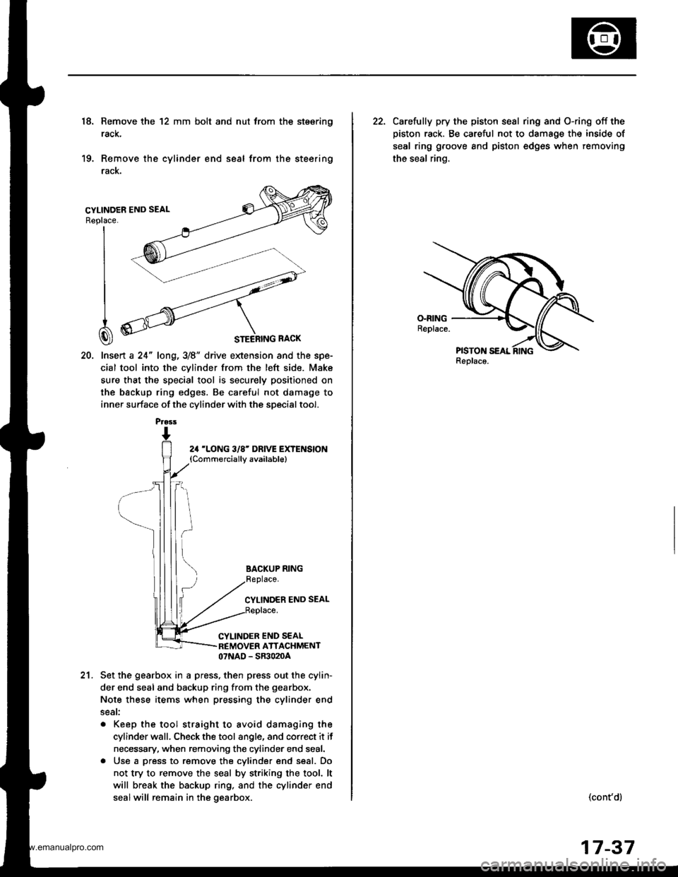
18. Remove the 12 mm bolt and nut trom the stsering
rack,
19. Remove the cylinder end seal from the steering
racK.
20. lnsert a 24" long,3/8" drive extension and the spe-
cial tool into the cvlinder from the left side. Make
sure that the special tool is securely positioned on
the backup ring edges. Be careful not damage to
inner surface of the cylinder with the special tool.
Replace.
I
I
I
CI
24 'LONG 3/8' DRIVE EXTENSION(Commerciallv available)
BACKUP RING
CYLINDER END SEAL
CYLINDER END SEALREMOVER ATTACHMENT07NAD - SR3020A
21.Set the gearbox in a press, then press out the cylin-
der end seal and backup ring from the gearbox.
Note these items when pressing the cylinder end
seat:
. Keep the tool straight to avoid damaging the
cylinder wall. Check the tool angle, and correct it if
necessary, when removing the cylinder end seal.
. Use a press to remove the cylinder end seal. Do
not try to remove the seal by striking the tool. lt
will break the backup ring, and the cylinder end
sealwill remain in the gearbox.
Prass
22. Carelully pry the piston sesl ring and O-ring off the
piston rack. Be careful not to damage the inside of
seal ring groove and piston edges when removing
the seal ring.
Replaco.
(cont'dl
17-37
www.emanualpro.com