1999 HONDA CR-V Tie rod
[x] Cancel search: Tie rodPage 17 of 1395
![HONDA CR-V 1999 RD1-RD3 / 1.G Workshop Manual
Under-hood Emissions Control Label
Emission Group ldentification
(1997 modell
Example:
VACUUM HOSE ROUTING DIAGRAM
LOADED IM TEST]NG OF PERMANENT fOUB WHEEL OSVE OR TRACT ON CONTROLEOLJIPPEDVEHTCLES HONDA CR-V 1999 RD1-RD3 / 1.G Workshop Manual
Under-hood Emissions Control Label
Emission Group ldentification
(1997 modell
Example:
VACUUM HOSE ROUTING DIAGRAM
LOADED IM TEST]NG OF PERMANENT fOUB WHEEL OSVE OR TRACT ON CONTROLEOLJIPPEDVEHTCLES](/manual-img/13/5778/w960_5778-16.png)
Under-hood Emissions Control Label
Emission Group ldentification
(1997 modell
Example:
VACUUM HOSE ROUTING DIAGRAM
LOADED IM TEST]NG OF PERMANENT fOUB WHEEL OSVE OR TRACT ON CONTROL'EOLJIPPEDVEHTCLES MUST BE CONDUCTED ON A IOUR WHEEL DR VE SPEEO SYNCHRON ZED
ANON LOADEDTESTPBO(EOUBEMUSIBEPERFORMEO
50ST (50 Statesl:
THIS VEHICLE CONFOBMS TO U.S. EPA AND STATE OF
CALIFORNIA REGULATIONS APPLICABLE TO 1997
MODEL YEAR NEW LIGHT DUTY TRUCKS.
49ST {49 Statos/Federall:
THIS VEHICLE CONFORMS TO U.S. EPA REGULATIONS
APPLICABLE TO 1997 IVIODEL YEAR NEW LIGHT DUTY
TRUCKS.
CAL (Calitornial:
THIS VEHICLE CONFORMS TO U.S. EPA AND STATE OF
CALIFORN IA REGULATIONS APPLICABLE TO '1997
MODEL YEAR NEW TLEV LIGHT DUTY TRUCKS
PROVIDED THAT THIS VEHICLE IS ONLY INTRODUCED
INTO COMMERCE FOR SALE IN THE STATE OF
CALIFORNIA.
Ii/PORTANT VEHICLE INFORIMATIONENGINE FAMILY VHN2 OIJCrcKDISPIACEMENT'2 OLITEREVAPORAT VE f AM]LY VNNl0778YMBP
CATALYSTREfERTOSEBVICEMANUALfORAODITIONAL NFORMATON.TUNT I-]P CONDITIONSENGINE AT NORI\,!AL OPERATNG TEMPERATURE,ALLACCESSOR ES TL]RNED OFF COOLING FAN OIFTRANSM1SSION NNEUTRALNO OTHEB ADJUSTMENIS NEEDED
ap' | \6( Zror '. ND \. 61F L r
TNIS VENICLE CONFORMS TO U.S EPA REGUI.ATIONSAPPI CASLE TO I99] MODET YEAR N€W L GNI DUTY TRACKS
@
Engine Family: vHN2.o l JGKE
Engine and Evaporative Families
T_fT
Model Year I Iv:1s97 | LManufaqturer iHN: Honda I
Displacement
Class
1: Light Duty Vehicle
Fuol Systom ,nd Numb€r of valves
J: Electronic Sequential Multiport
Injection (three or more valves per
cylinder)
Fuel Type
G: Gasoline
Standard
F: 49 or 50 States Tier 1
K: 49 or 50 States Tier 1
1: California Tier 1
2: California TLEV
3: California LEV
4: California ULEV
"r0", "*,
T|
V: 1997
Manufacturer
HN: Honda
Catalyst
E, F, G, H: Three Way Catalyst
OBD
K - T: OBD Equipped
Evaporative Family:
Storago System
1: Canister
Canistor Working Capacity (gramsl
Canister Conf igulation
A: Plastic Housing (Closed Bottom)
B: Plastic Housing (OPen Bottom)
Fusl System
Y: Fuel Injection
FuelTank
M: Metal
Standard
A: Current Evap
B: Enhanced Evap
Wild C.rd
VHNlOTTBYMBP
1-1 5
www.emanualpro.com
Page 853 of 1395
Troubleshooting
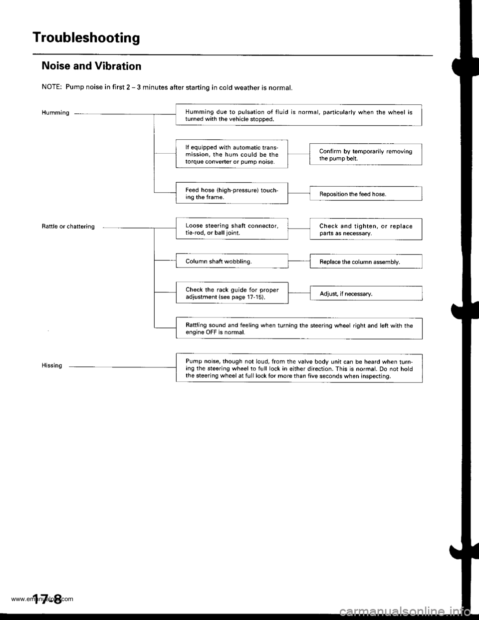
Noise and Vibration
NOTE: Pump noise in first 2 - 3 minutes after starting in cold weather is normal.
Humming
Rattle or chattering
Humming due to pulsation of fluid is normal, particularly when the wheel isturned with the vehicle stooDed.
lf equipped with automatic trans-mission, the hum could be thetorque converter or pump noase.
Confirm by temporarily removingthe pump belt.
Feed hose (high-pressure) touch-ing the frame.Beposition the feed hose.
Loose steering shaft connector,tie-rod, or balljoint.Check and tighten, or replaceparts as necessary,
Column shaft wobbling.Roplace the column assembly.
Check the rack guide for properadjustment (see page 17-15).Adjust, if necessary.
Rattling sound and feeling when turning the steering wheel right and left with th€engine OFF is normal.
Pump noise, though not loud, from the valve body unit can be heard when turn-ing the steering wheel to full lock in either direction. This is normal. Do not holdthe steering wheel at full lock lor more than five seconds when inspecting.
17-8
www.emanualpro.com
Page 855 of 1395
Troubleshooting
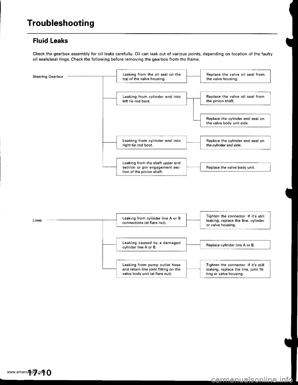
Fluid Leaks
Check the gearbox assembly for oil leaks carefully. Oil can leak out ot various points, depending on location of the faulty
oil seals/seal rings. Check the following before removing the gearbox from the frame.
Steering GearboxLeaking from the oil seal on thetop of the valve housing.Replace the valve oil seal fromthe valve housing.
Leaking from cylinder end intoleft tie rod boot.Replace the valve oil seal fromthe pinion shaft.
Replace the cylinder end seal onthe valve body unit side.
Leaking from cylinder end intoright tie-rod boot.Replace the cylinder end seal onthe cylinder end side.
Leaking lrom the shaft upper endsection or pin engagement sec-tion of the pinion shaft.Replace the valve body unit.
Tighten the connector. It it's stillleaking, replace the line, cylinderor valve housing.
Leaking from cylinder line A or Bconnections (at tlare nut).
Leaking caused by a damagedcylinder line A or B.Replace cylinder line A or B.
Leaking from pump outlet hoseand return line joint fitting on thevalve body unit {at tlare nut}.
Tighten the connector. ll it's stillleaking, replace the line, joint fit-ting or valve housing,
17-10
www.emanualpro.com
Page 876 of 1395
Power Steering Gearbox
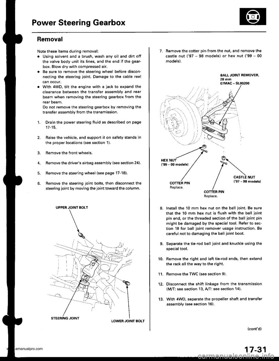
Removal
Note these items during removal:
. Using solvent and a brush, wash any oil and dirt off
the valve body unit its lines, and the end if the gear-
box. Blow dry with compressed air.
. Be sure to remove the steering wheel before discon-
necting the steering joint. Damage to the cable reel
can occur.
. With 4WD. tilt the engine with a jack to expand the
clearance between the transfer assembly and rear
beam when removing the steering gearbox from the
rear oeam.
Do not remove the steering gearbox by removing the
transfer assembly from the transmission.
1. Drain the power steering fluid as described on page'17-15.
Raise the vehicle, and suppon it on safety stands in
the proper locations (see section 1).
Remove the front wheels,
Remove the drive/s airbag assembly {see section 24).
Remove the steering wheel {see page 17-18).
Remove the steering joint bolts, then disconnect the
steering joint by moving the joint toward the column.
UPPER JOINT BOLT
LOWER JOINT BOLT
13.
7. Remove the cotter pin from the nut, and remove the
castle nut {'97 - 98 models) or hex nut ('99 - 00
models).
COTTER PINReplace.
Install the 10 mm hex nut on the ball joint. Be sure
that the 10 mm hex nut is flush with the ball joint
pin end, or the threaded section of the ball joint pin
might be damaged by the special tool. Refer to sec-
tion 18 for ball joint remover usage instruction, Be
careful not to damaging the ball joint boot.
Separate the tie-rod ball joint and knuckle using the
special tool.
Remove the right and left tie-rod ends, then extend
the rack all the way to the right.
Remove the TWC (see section 9).
Disconnect the shift linkage from the transmission
(M/T: see section 13, A/T: see section 14).
With 4WD. separate the propeller shaft and transfer
assembly (see section 161.
10.
11.
(cont'd)
17-31
www.emanualpro.com
Page 894 of 1395
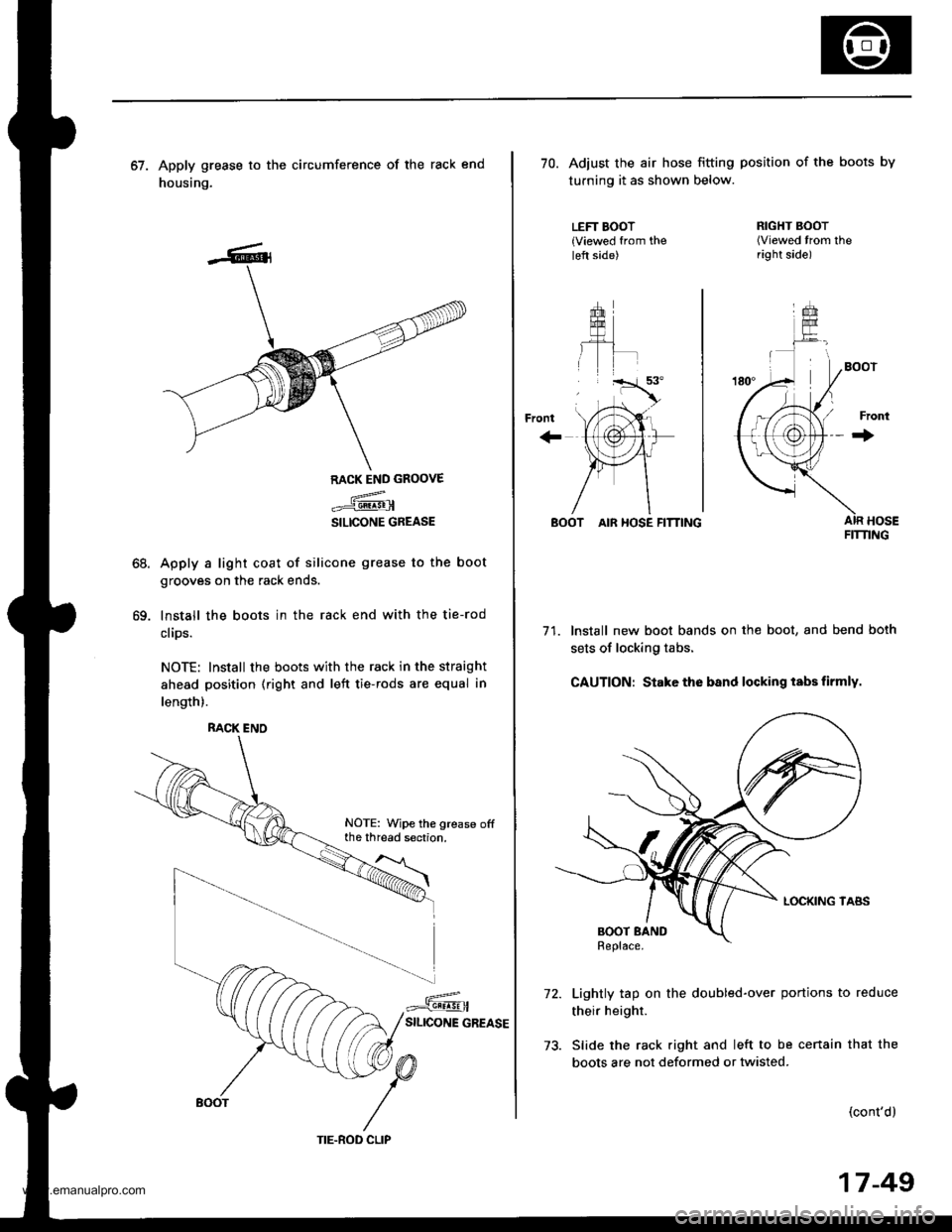
67. Apply grease to the circumference of the rack end
housing.
68.
69.
RACK END GROOVE
.={@
SILICONE GREASE
Apply a light coat of silicone grease to the boot
grooves on the rack ends.
lnstall the boots in the rack end with the tie-rod
clips.
NOTE: Install the boots with the rack in the straight
ahead position (right and left tie-rods are equal in
length).
RACK ENO
NOTE: Wipe the grease offthe thread section.
TIE.ROD CLIP
17-49
70. Adiust the air hose fitting position of the boots by
turning it as shown below.
LEFT BOOT{Viewed from theleft side)
+rom
''rT.a'.
, tri"
\,'tAr-
{,1@}tr
)Fr1
/\
RIGHT BOOT(Viewed trom theright side)
Front
+
BOOT AIR HOSE FITTING
71. Install new boot bands on the boot, and bend both
sets of locking tabs.
CAUTION: Stake the band locking tabs firmly.
Lightly tap on the doubled-over portions to reduce
their height.
Slide the rack right and left to be cenain that the
boots are not deformed or twisted.
(cont'd)
FIT'I'ING
www.emanualpro.com
Page 898 of 1395
't 4.
15.
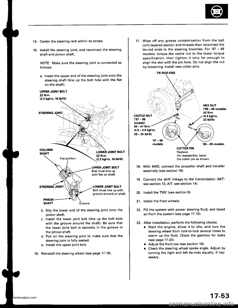
Center the steering rack within its stroke.
Install the steering joint, and reconnect the steering
shaft and pinion shaft.
NOTE: Make sure the steering joint is connected as
follows.
a. Insen the upper end of the steering joint onto the
steering shaft (line up the bolt hole with the flat
on the shaft).
UPPER JOINT BOLT22 N.m12.2 kgf.m, 16lbl.ft,
STEERING JOINT
COLUMNSHAFTLOWER JOINT BOLT22 N.m12.2 kgf.m, 16lbtftl
UPPER JOINT BOLTBolt must line upwith tlat on shatt.
LOWER JOINT BOLTBolt must line up withgroove around on shaft.
PINIONSHAFT
b, Slip the lower end of the steering ioint onto the
pinion shaft.
c. Install the lower joint bolt (line up the bolt hole
with ths groove around the shaft). Be sure that
the lower joint bolt is securely in the groove in
the pinion shaft.
d. Pull on the steering joint to make sure that the
steering joint is fully seated.
e, Install the upper joint bolt,
Reinstall the steering wheel {see page'17-19).16.
17-53
17. Wipe off any grease contamination trom the ball
joint tapered section and threads then reconnect the
tie-rod ends to the steering knuckles. For'97 - 98
models; torque the castle nut to the lower torque
specification, then tighten it only far enough to
align the slot with the pin hole. Do not align the nut
by loosening. Install new cotter pins.
CAST1T NUT(9t - 98modol!)
HEX NUTl'g!t - 00 modeb)il:l N.m14.4 ksl.m,32 tbf.f0
39 - iU N'm
lil.o - 4.8 kgl.m,
29 - 35 tbf.ftl
18.
19.
20.
21.
22.
23.
'99 - lD modeb:
COTTER PINRePlace.on reassembly, bendthe cotter Pin as shown.
With 4WD, connect the propeller shaft and transfer
assembly (see section 16).
Connect the shift linkage to the transmission (M/T:
see section 13, A,/T; see section 14).
Installthe Twc (see section 91.
lnstall the front wheels,
Fill the system with power steering fluid, and bleed
air from the system (see page 17-15).
After installation. perform the following checks.
. Start the engine, allow it to idle, and turn the
steering wheel from lock-to-lock several times to
warm up the fluid. Check the gearbox for leaks
(see page 17-23).
. Adjust the front toe (s€e section 18).
. Check the steering wheel spoke angl€. Adjust by
turning the right and left tie-rods equally, if nec-
essary.
TIE.ROO END
www.emanualpro.com
Page 903 of 1395
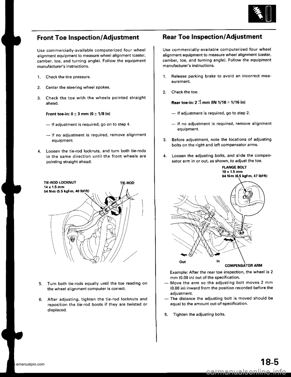
Front Toe Inspection/Adjustment
Use commercially-available computerized four wheel
alignment equipment to measure wheel alignment (caster,
camber, toe, and turning angle). Follow the equipment
manufacturer's instructions,
3.
1.Check the tire pressure.
Center the steering wheel spokes.
Check the toe with the wheels pointed straight
ahead.
Front toe-in: 0 i 3 mm {0 t 1/8 inl
- lf adjustment is required, go on to step 4.
- lf no adjustment is required, remove alignment
equipment.
Loosen the tie-rod locknuts, and turn both tie-rods
in the same direction until the front wheels are
pointing straight ahead.
5.Turn both tie-rods equally until the toe reading on
the wheel alignment computer is correct.
After adjusting, tighten the tie-rod locknuts and
reposition the tie-rod boots if they are twisted or
displaced.
sir N m (5.5 kgJ.m, 'O lbf.ft)
Rear Toe Inspection/Adjustment
Use commercially-available computerized four wheel
alignment equipment to measure wheel alignment (caster,
camber. toe, and turning angle). Follow the equipment
manufacturer's instructions.
Release parking brake to avoid an incorrect mea-
surement.
Check the toe.
Ro8r toe-in: 2 :1 mm {lN l/16:t 1/16 in,
- lf adjustment is required, go to step 2.
- lf no adiustment is required. remove alignment
equrpmenr.
Before adjustment, note the locations of adjusting
bolts on the right and left compensator arms.
Loosen the adjusting bolts, and slide the compen-
sator arm in or out. as shown, to adiust the toe.
1.
FLANGE BOLT'10 x 1.5 mm
COMPENSATOR ARM
Example: After the rear toe inspection, the wheel is 2
mm (0.08 in) out of the specification.- Move the arm so the adjusting bolt moves 2 mm
{0.08 in) inward from the position recorded before the
adjustment.- The distance the adjusting bolt is moved should be
equal to the amount out-of-specification.
5. Tighten the adjusting bolts.
6a N.m 16.5 kgf.m, 47 lbf'ftl
18-5
www.emanualpro.com
Page 1322 of 1395
)Steering-related Precautions
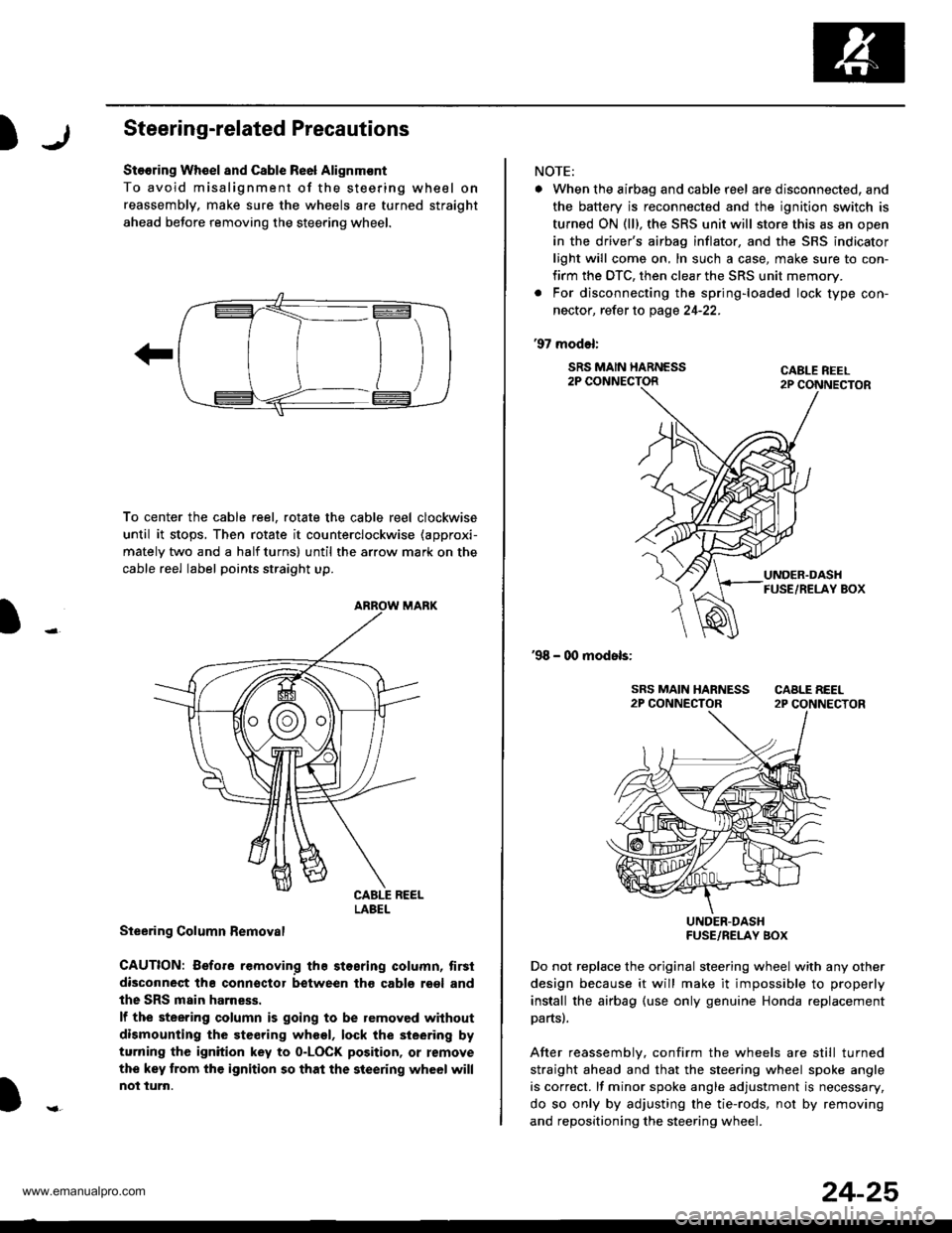
Stooring Wh€el and Csble Re6l Alignm€nt
To avoid misalignment of the steering wheel on
reassembly, make sure the wheels are turned straight
ahead beJore removing the steering wheel.
To center the cable reel, rotate the cable reel clockwise
until it stops, Then rotate it counterclockwise (approxi-
mately two and a half turns) until the arrow mark on the
cable reel label points straight up.
Steering Column Bemoval
CAUTION: Before removing the stosring column, tirsi
disconneqt tha connsctor between tho cabls roel and
the SRS main harness.
lf the steering column is going to be removed without
dismounting the steering wheel, lock the sieering by
turning the ignition key to o-LOCK position, or remove
the key trom the ignition so that the steering wheel will
not turn.
LABEL
NOTE:
. When the airbag and cable r6el are disconnected, and
the battery is reconnected and the ignition switch is
turned ON (ll), the SRS unit will store this as an open
in the driver's airbag inflator, and the SRS indicator
light will come on, In such a case, make sure to con-
firm the DTC, then clear the SRS unit memory.
. For disconnecting the spring-loaded lock type con-
nector, refer to page 24-22.
'97 model:
SRS MAIN HARNESS2P CONNECTORCABLE REEL2P CONNECTOR
'98 - 00 models:
UNDER-DASHFUSE/RELAY BOX
Do not replace the original steering wheel with any other
design because it will make it impossible to properly
install the airbag (use only genuine Honda replacement
partsl.
After reassemblv, confirm the wheels are still turned
straight ahead and that the steering wheel spoke angle
is correct. lf minor spoke angle adjustment is necessary,
do so only by adjusting the tie-rods, not by removing
and repositioning the steering whee .
24-25
www.emanualpro.com