Page 292 of 1395

PGM-FI System
Manifold Absolute Pressure (MAPI Sensor
The scan tool indicates Diagnostic Trouble Code (DTC) POl07: A low input (high vacuum) problem in theManifold Absolute Pressure (MAP) sensor,
The MAP sensor convens manifold absolute pressure into electrical signals and inputs the ECM/pCM.
OUTPUIVOLTAGE
tvl3.s
3.0
2.5
2.O
1.5
1.0
0.5
o .5 ro- 15^ 1olin.H9) GAUGEREADIT{G
lmmHgl
3025
100 200 300 a00 5oo 6fi, 7d)
MAP SENSOR 3P CONNECTOR IC131I
vccl(YEL/RED}
Th6 MIL has b€en reoorted on.DTC P0107 is 3tored.
Problom verification:1. Turn the ignition switch ON lll).2. Check the lvlAP with the scanroot.
lrtormittem tailu.e, lystam b OKat thb timo. Check tor poor con-noctions or loosa wird at C131(MAP rensor) and rt the ECM/PCM.
ls approx. 101 kPa (760 mmHg,30 in.Hg),2.9 V indicated?
Check for an op6n in wi.o IVCC1linel:1. Turn the ignition switch OFF.2. Disconnect the MAP sensorconnector,3. Turn the ignition switch ON {ll}.4. Measure voltage between theMAP sensor connector No. 1termanal and No. 2 terminal.
Roprir op€n in the wir6 bstweentho ECM/PCM (D4, C19*l and theMAP sensor.
ls there approx. 5 V?
(To page 11-91)
11-90
Wiro side ol temale terminals
www.emanualpro.com
Page 294 of 1395
![HONDA CR-V 1999 RD1-RD3 / 1.G Workshop Manual
PGM-FI System
Manifold Absolute Pressure (MAP) Sensor (contd)
[tn,t nn-] The scan tool indicates Diagnostic Trouble Code (DTC) P0108: A high voltage (low vacuum) problem in the|jg Manifold Absolute HONDA CR-V 1999 RD1-RD3 / 1.G Workshop Manual
PGM-FI System
Manifold Absolute Pressure (MAP) Sensor (contd)
[tn,t nn-] The scan tool indicates Diagnostic Trouble Code (DTC) P0108: A high voltage (low vacuum) problem in the|jg Manifold Absolute](/manual-img/13/5778/w960_5778-293.png)
PGM-FI System
Manifold Absolute Pressure (MAP) Sensor (cont'd)
[tn,t nn-] The scan tool indicates Diagnostic Trouble Code (DTC) P0108: A high voltage (low vacuum) problem in the|jg Manifold Absolute Pressure (MAP) sensor.
MAP SENSOR 3P CONNECTOR IC131I
Wire side of female terminals
vcclIYEL/RED}
PCM CONNECTOR D I16PI
JUMPER WIRE
sGlIGRN/WHTI
Wire side of lemale termin6ls
1
(To page 11,93)': '98 - 00 models
1-92
tcRN/wHrll IIRED/GRN|
The MIL has boen reported on.DTC m108 is slored.
Problem veritication:1. Start the engine. Hold theengine at 3,000 rpm with noload (in Park or neutral) untilthe radiator fan comes on, thenlet it idle.2. Check the MAP with the scantool.
Intermittent tailuro, system i3 OKat this time. Check tor ooor con-nections or loose wires at C131IMAP s6nsor) snd the ECM/rcM.
ls 101 kPa {760 mmHg,30 in.Hg),2.9 V or higher indicated?
Check Ior an open in the MAPsensor:1. Turn the ignition switch OFF.2. Disconnect the MAP sensor3P connector.3. lnstall a jumper wire betweenthe MAP sensor 3P connectorterminals No.3 and No.2.4. Turn the ignition switch ON {ll).5. Check the MAP with the scantool.
ls 10'l kPa (760 mmHg,30 in.Hg),2.9 V or higher indicated?
Check for an open in wire (SGlliDel:1. Remove the jumper wire.2. Measure voltage between theMAP sensor 3P connector ter-minals No. 1 and No- 2.
R6p.ir open in the wire betwoenthe ECM/PCM (D12, CTrl and theMAP sensor.
ls there approx. 5 V?
Check for an open in the wire(MAP line):1. Turn the ignition switch OFF.2. lnstall a iumper wire on thePCM connectors between D3and D12.3. Turn the ignition switch ON (ll).4. Check the MAP wirh the scantool.
Ropair opon in the wire betweenthe PCM {D3, .nd the MAP son-3('t.
ls 101 kPa 1760 mmHg, 30 in.Hg),2.9 V or higher indicated?
YES
www.emanualpro.com
Page 296 of 1395
PGM-FI System
Manifold Absolute Pressure (MAP) Sensor (cont'dl
The scan tool indicates Diagnostic Trouble Code (DTC) P1128: Manifold Absolute pressure (MAp) lower thanexoected.
The scan tool indicates Diagnostic Trouble Code (DTC) P'l129: Manifold Absolute Pressure (MAP) higher thanexpected.
l
- The MIL has be6n r€ported on.- DTC Pl128 is stored.
Problom verification:1. Turn the ignition switch ON 1lli.2. Check the MAP with the scantool,
ls 54.1 kPa (406 mmHg, 16.0 in.Hg),1.61 V or higher indicated?I to.mittent failure, 3ydom i! OKal thbtimc,
- The MIL has boen reportod on.- DTC Pl129 is stored.
Problem veritication:1. Start the engine. Hold theengine at 3,000 rpm with noload lin Park or neutral) untilthe radiator fan comes on,then Iet it idle.2. Check the MAP with the scantool,
ls 43.3 kPa (325 mmHg, 12.8 in.Hg),'1.32 V or less indicated?Intarmittani fuilure, systom i3 OKat this time.
11-94
www.emanualpro.com
Page 314 of 1395

PGM-FI System
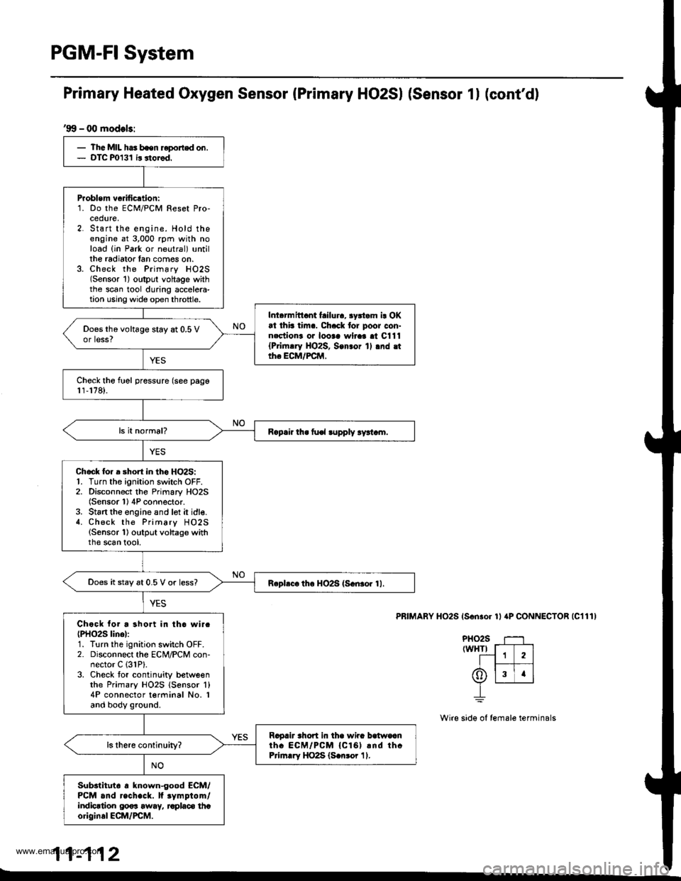
'99 - 00 models:
- The MIL has bsen reported on.- DTC P0131 ir storod.
Problem ve fication:1. Do the ECM/PCM Reset Pro-cedure,2. Start the engine. Hold theengine at 3,000 rpm with noload {in Park or neutral) untillhe radiator tan comes on.3. Check the Primary HO2S(Sensor 1) oltput voltage withthe scan tool during accelera-tion using wide op€n throttle.
Inl.rmittant failura, 3yrtam i! OKat thb tim.. Ch.ck tor poor con-nectiona oa looaa wlraa al C111{Pri|n.ry HO2S, Son3or 1l .nd .ttho ECM/FCM,
Does the voltage stay at 0.5 Vor less?
Check tho fuel pressure (see pago1r,178).
R.p.ir th. fu€l lupply ry!t.m.
Chock lor a short in tho HO2S:1. Turn the ignition switch OFF.2. Disconnect the Primary HO2S(Sensor 1) 4P connector.3. St6rt the engine and lot it idle.4. Check the Primary HO2S(Sensor 1) output voltage withthe scan tool,
Does it stay 6t 0.5 V or less?Rephc. th6 HO2S (S.n3or 11.
Chock for a short in tho wirc(PHO2S lino):1. Turn the ignition switch OFF.2. Disconnect the ECM/PCM con-nector C (31P).
3. Check tor continlity betweenthe Primary HO2S {Sensor 'l}
4P connector terminal No. Iand body ground.
Ragah rhort in tha wira balwoanth. ECM/PCM {Cl61 rnd thcPrirn.ry HO2S (S.n3or 11.
Substltut6 a known-good ECM/PCM and recheck. lf rymptom/indicrtion 00os away, raplaco thcoriginal ECM/PCM.
Primary Heated Oxygen Sensor (Primary HO2SI (Sensor 1l (cont'd)
PRIMARY HO2S (Son.or 1l aP CONNECTOR |C111)
PHO2S T--1rwHTr f-T---]
--1 1 2lI t--- 1t6)lslrlv L__r__J
_L
Wire side ol female terminals
11-112
www.emanualpro.com
Page 339 of 1395

Barometric Pressure (BARO) Sensor
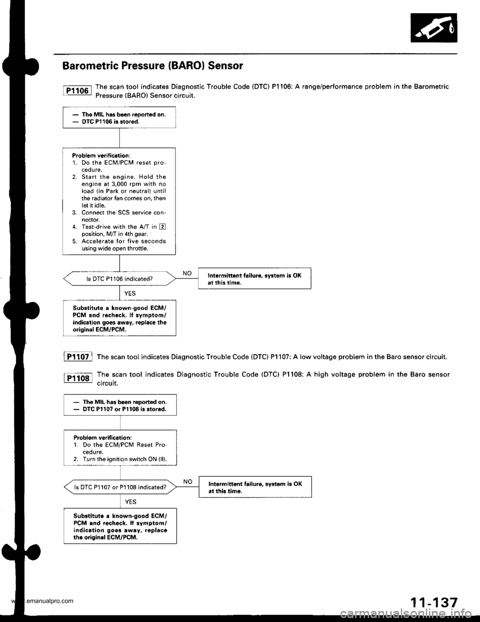
The scan tool indicates Diagnostic Trouble Code (DTC) P1106: A range/performsnce problem in the Barometric
Pressure {BARO) Sensor circuit.
The MIL has been reDorted on.OTC Pl106 b slored.
Problem ve.ification:1. Oo the ECM/PCM reset pro'
ceoure.2. Start the engine. Hold theengine at 3,000 rpm with noload (;n Park or neutral) untilthe radiator lan comes on, thenlet it idle.3. Connect the SCS service con-nector,4. Test'drive with the A/T in Eposition, M/T in 4th gear.
5. Accelerate Ior five secondsusing wide open throttle.
Intermittent fsilure, sy3tom i5 OKat this time.ls DTC P1106 indicated?
Substitute a known-good ECM/PCM .nd recheck. It symptom/indication goes away, replace theorigioal ECM/PCM.
fTiloz l
tP11o8l
The scan tool indicates Diagnostic Trouble Code (DTC) P1107: A low
The scan tool indicates Diagnostic Trouble Code (DTC) Pl108: A
circuit.
voltage problem in the Baro sensor circuit.
high voltage problem in the Baro sensor
- The MIL h.3 b€en roport€d on.- OTC Pl10? or Pl108 i3 stored.
Problom veritic.lion:L Do the ECM/PCM Reset Pro-cedure.2. Turn the ignition switch ON (lli.
Intarmittoni failure, lystom b OKat thb time.ls DTC P1107 or P1108 indicated?
Sub3tituto a known-good ECM/PCM and rcch6ck. ll symptom/indication 9oo3 away. .oplacorho o.igin.l ECM/PCM.
www.emanualpro.com
Page 357 of 1395

Air Conditioning Signal
This signals the EcM/PcM when there is a demand for cooling from the air conditioning system.
'97 modol:
Wire side of lemale terminals
PCM CONNECTOR C (31PI
ACS IBLU/RED)
PCM CONNECTOR A (:TIPI
(cont'd)
1 1-1 55
Chock for a shorl in thc wiro(ACS linol:1. Turn the ignition switch OFF.2. Disconnect the A/C pressure
switch 2Pconneclor.3. Turn the ignition switch ON (ll).,1. [Ieasu re voltage betweenPCM connector terminals C5
and A9.
Check for . .hon in the wire IAGSlinel:1. Turn the ignition switch OFF.2. Disconnect PCM connector C(31P).
3. Check for continuity betweenbody ground and PCM con-nector torminal C5.
Reoaii short in tho wire b€twoenrh6 PCM (Csl and the A/C pres-
3urc 3witch.
- Subcdtrte a known{ood PCMand recheck. lf pr6actibed volt-age is now av{ilable, roplacethe origind PCM,- Soe the eir conditionor in3p€c-lion lsee soction 221.
Check tor an opon in the wite(ACC lino):1. TLrrn the ignition switch OFF.2. Roconnect the A/C pressure
switch 2P connector.3. Turn the ignition switch ON (ll).
4. Momenta rily connect PCMconnector terminals A9 and417 with a iumper wire sev'eraltimes,
Wire side of female terminals
JUMPER WIRE
(To page 11-156)Wire side oI Iemale terminals
www.emanualpro.com
Page 359 of 1395

'98 - 00 models:ECM/PCM CONNECTORS
ECM/PCM CONNECTOR A (32PI
Wire side of female terminals
ECM/PCM CONNECTORS
A (32P1
ACC (BLK/REOI
LG1 (BRN/BLKI
{cont'd)
11-157
A {32P1
Check for a shott in the wire
{ACS linel:1. Turn the ignition switch OFF.
2. Disconnect the A/C Pressureswitch 2P connector.3. Turn the ignition switch ON (ll)
4. Measure vo ltage betweenECM/PCM connector terml
nals A27 and 820.
Check tor . short in the wire IACSlinel:1. Turn the ignition switch OFF.
2. Disconnect ECM/PCM connec-tor A (32P).
3. Check for continuity betweenbody ground and ECM/PCMconnector terminal A27.
ls there battery voltage?
R.oak short in the wile between
rhe ECM/PCM (A271 and the A/C
Dressure switch.ls there continuitv?
Sub6titute a known{ood ECM/
rcM and recheck. lf pte6cribed
voltage i3 now available, re'pl.ce the origioal ECM/rcM.See ih6 air conditioner inspec-
tion (s6e section 221.
Check for an open in the wire(ACC line):'1. Turn the ignition switch OFF.
2. Reconnect the A/C Pressureswitch 2P conneclor.3. Turn the ignition switch ON (ll).
4. Momentarily connect ECM/PCM connector terminals A17
and 820 with a jumPer wireseveralllmes,
{To page 11 158)JUMPER WIRE
www.emanualpro.com
Page 364 of 1395

ldle Gontrol System
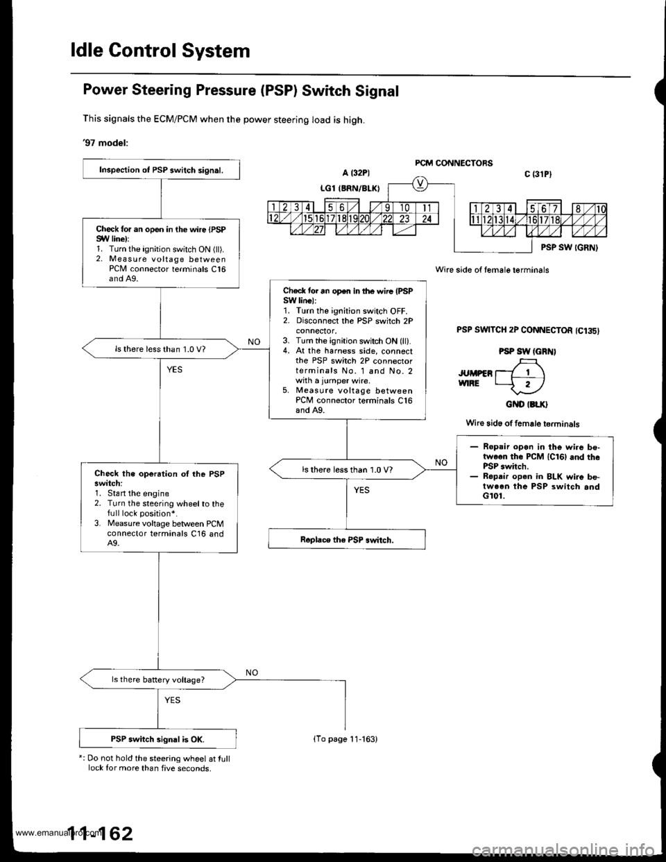
Power Steering Pressure (PSP) Switch Signal
This signals the ECM/PCM when the power steering load is high.
'97 model:
*: Do not hold the steering wheel at tulllock for more than five seconds,
Wire side of female terminals
PSP SWTTCH 2P CONNECTOR 1C135)
PSP SW (GRN)
JUMPER T_7 1 \vnRE t--f r)
GND IBLK}
Wire 3id6 of female terminals
Inspection ot PSP switch signal.
Check for an open in the wire {PSPSYV line):1. Turn the ignition switch ON (ll).2. Measure voltage betweenPCN4 connector terminals C16and A9.
Check tor an open in lhe wire (PSPSW linel:1. Turn the ignition switch OFF.2. Disconnect the PSP switch 2Pconnecror,3. Turn the ignition switch ON (ll).4. At the harness side, connectthe PSP switch 2P connectorterminals No. 1 and No. 2with a jumper wire.5, Measute voltage betweenPCM connector terminals C16and A9.
ls there less than 1.0 V?
- Ropsir open in the wi.e be-twoon the PCM lcl6l and thePSP switch.- Ropdir open in BLK wire be-tween the PSP switch andG101.
ls there less than 1.0 V?Check the operation oI lhe PSPswitch:1. Stan the engine2. Turn the steering wheelto thefull lock position*.
3. Measure voltage between PCMconnector terminals C16 andA9.
ls there battery voltage?
PSP switch signal is OK.(To page 11-163)
www.emanualpro.com