Page 677 of 1395

Pressure Testing
Changing
NOTE: Keep all foreign particles out of the transmis-
sion.
1. Bring the transmission up to operating temperature
(the radiator fan comes on) by driving the vehicle.
Park the vehicle on level ground. turn the engane
off. then remove the drain Plug.
NOTE: lf a cooler flusher is to be used, see page
14-264 and 14-265.
TRANSMISSIONEND COVER
DRAIN18 x 1.5 mmSEALING WASHEBReplace.49 N.m {5.0 kgt.m, 36 lbf.tl)
Reinstall the drain plug with a new sealing washer,
then refill the transmission with the recommended
fluid to the uDper mark on the dipstick. Always use
Genuine Honda Premium Formula Automatic
Transmission Fluid (ATF) Using a non-Honda ATF
can affect shift quality.
Automatic Transmission Fluid Capacity:
4WD;
2.9 { (3.1 US qt. 2.6 lmp qt) 8t change
5.8 ? {7.2 US $, 6.0 lmp qt} at ovethaul
2WD:
2.7 | l2.S US qt,2.1lmp qtl ai change
5.9 ? {6.2 US $, 5.2 lmp qtl at ovolhaul
2.
a
a
1.
Wlrile testing, be careful of the rotaling wheols.
Mako sure lifts, iacks, and safety stands ar€ placed
properly (see scction 11.
Before testing, be sure the transmission fluid is
filled to the proPer level.
4WD:
Raise the vehicle (see section 11.
2WD:
Raise the front of the vehicle, and make sure it is
securely supported. Set the parking brake, and block
both rear wheels securely.
Allow all four wheels {4WD) or front wheels (2wD}
to rotate freely.
Warm up the engine (the radiator fan comes on),
then stop it and connect the tachometer.
Connect the oil pressure gauges to each inspection
hole securely, and do not allow dust or other foreign
particles to enter the inspection holes.
TOROUE: 18 N'm ll.8 kgf'm, 13 lbf'ft)
5.
A/T PRESSURE HOS€,2210 mm07MAJ - PYiOllA
{4 Requircd}
,4'/"' ,a
W'
A/T PRESSURE HOSEADAPTER07MAJ - PYt0120(il Rcquiledl
6. Measure the following Pressure:. Line Pressure ..........,14-162
. 1st. 1st-hold Clutch Pressure .............'. 14-162
. 2nd,3rd and 4th Clutch Pressure .......... 14-163
7. Install new sealing washers and the sealing bolts in
the inspection holes, and tighten to the specified
toroue.
(cont'd)
A/T OIL PRESSUREGAUGE SET W/PANEL07{06 - 0020400
/4\\-J-- (
+..\.-.\-'-\
A/T LOW PBESSUREGAUGE w/PANEL07406 - 0070300
TOROUE: 18 N'm 11.8 kgf'm, 13 lbf'ft)
14-161
www.emanualpro.com
Page 764 of 1395

Transfer Assembly
35.
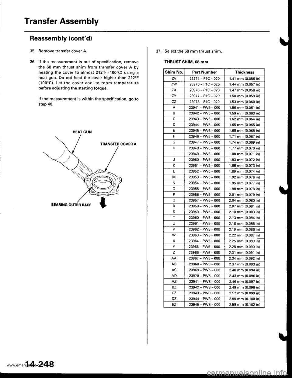
Reassembly (cont'dl
36.
Remove taansfer cover A.
lf the measurement is out of specification, remove
the 68 mm thrust shim from transfer cover A by
heating the cover to almost 212"F (100"C) using a
heat gun. Do not heat the cover higher than 212"F(100'C). Let the cover cool to room temperature
before adjusting the starting torque,
lf the measurement is within the specification, go to
step 40.
HEAT GUN
14-248
37. Select the 68 mm thrust shim.
THRUST SHIM, 58 mm
Shim No.Part NumberThickness
zv23974-P1C-O201.41 mm (0.056 in)
zw23975-P1C-O201.44 mm (0.057 in)
zx23976-P1C-020'1.47 mm (0.058 in)
ZY23977 - P1C - O201.50 mm (0.059 in)
zz23978-P1C-0201.53 mm 10.060 in)
23941 PW5 - 000'1.56 mm {0.061 in)
B23942-PWs-0001.59 mm 10.063 in)
c23943 - PWs 0001.62 mm (0.064 in)
D23944-PW5-0001.65 mm {0.065 in}
E23945 PWs - 0001.68 mm (0.066 in)
F23946 PWs - 0001.71 mm (0.067 in)
G23947 PWs - 0001.74 mm (0.069 ini
23948-PW5-0001.77 mm (0.070 ini
23949 PW5 0001.80 mm (0.071 in,
J23950-PWs-0001.83 mm {0.072 ini
K23951 - PWs - 0001.86 mm (0.073 in
L23952 PW5 - 0001.89 mm (0.074 in
23953 PWs - 0001.92 mm (0.076 in
N23954 PW5 - 0001.95 mm (0.077 in
o23955 PW5 0001.98 mm (0.078 in
P23956 - PWs 0002.01 mm (0.079 in
o23957-PW5-0002.04 mm (0.080 in
R23958, PWs 0002.07 mm (0.081 in
s23959-PW5-0002.10 mm (0.083 in
T23960 PW5 - 0002.13 mm (0.084 in
U2396'1 PW5 - 0002.16 mm (0.085 in
23962 PWs 0002.19 mm (0.086 in
23963 - PW5 0002.22 mm (0.087 in
X23964 - PW5 0002.25 mm (0.089 in
23965 PW5 - 0002.28 mm (0.090 in
z23966 PWs 0002.31 mm (0.091 in
23967-PWs-0002.34 mm (0.092 in
AB23968-PWs-0002.37 mm (0.093 in)
AC23969-PWs-0002.40 mm (0.094 in)
AD23970-PW5-0002.43 mm (0.096 in)
M23941 PW8 0002.46 mm (0.097 in)
BZ23942-PW8-0002.49 mm (0.098 in)
cz23943 - PW8 0002.52 mm (0.099 in)
DZ23944 PW8 - 0002.55 mm (0.100 in)
EZ23945-PW8-0002.58 mm (0.102 in)
www.emanualpro.com
Page 792 of 1395
Special Tools
Ret. No.Tool NumberOescriptionotvPage Reler€nce
o
@aa
@/il
tol
J - 38592
07GAD - PH7020'1
07JAB - 0010204
OTRAB _TB40lOB
07749 - 0010000
07965 - 6920101
Transfer Case Oil Seal lnstaller
Seal Driver
Holder Handle
Flange Holder
Driver
Hub Dis/Assembly Tool
1
1
1
1
1
1
15-20
15-19
tc-zt, z9
15-21,25
15-19
15-19
6\
@
15-2
www.emanualpro.com
Page 809 of 1395
Oil Seals
Replacement
1. Remove the oil seals from the differential housing.
Right side:
Left side:
2. Install the oil seals squarely using the special tools.
Be carelul not to damage the lip ol the oil seals.
Right side: Installation depth of the oil seal is 9 mm
(0.35 in) below the edge of the differential housing.
OIL SEAL
OIL SEAL
Left side: Install the oil seal flush with the edge of
the differential carrier assembly.
OIL SEAL
HUB DIS/ASSEMBLY TOOL07965 - 6920101
(cont'd)
15-19
www.emanualpro.com
Page 902 of 1395

Wheel Alignment
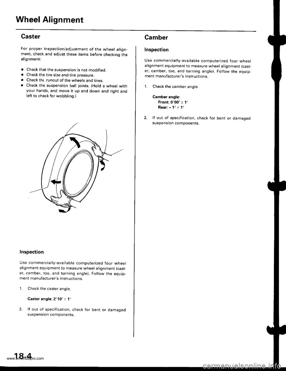
Caster
For proper inspection/adjustment of the wheel align-ment, check and adjust these items before checkinq thealignment:
. Check that the suspension is not modified.. Check the tire size and tire pressure.
. Check th( runout of the wheels and t;res,. Check the suspension ball joints. (Hold a wheel withyour hands, and move it up and down and right andleft to check for wobbling.)
Inspection
Use commercially-available computerized four wheelalignment equipment to measure wheel alignment (cast-
er, camber, toe, and turning angle). Follow the equip-ment manufacturer's instructions.
Check the caster angle.
Caster angle: 2'10':t 1"
lf out of specification, check for bent or damagedsuspension components.
1.
18-4
Camber
Inspection
Use commercially-available computerized lour wheelalagnment equipment to measure wheel alignment (cast,
er, camber, toe, and turning angle). Follow the equip,ment manufacturer's instructions.
1. Check the camber angle.
Camber angle:
Front: 0'00' 1 1"
Rear: - 1' :! 1"
2. lf out of specification, check for bent or damagedsuspensron components.
www.emanualpro.com
Page 1089 of 1395
POlNTx.y / I
'sad
POINT m3, m4
Upper Arm
M12 x P1.25
Locate Hole
POINT 3, s1
o14 {0.551 For Trailing Aim
POINT v
Fuel Tank Strap Poinr
2700.5 (106.32)SECTION BBRear Damoer Center
POINT n
FOINT
rg (0.3) Fuel TStrap Center
271,1(10,6.9)
o2010.8| Locate Hole
For Rear Cros3 Beam
For Reer Cross Beam
POINT w
Bear Damper LowerBushing Point
I
\-
ql
ol
.df
20-109
www.emanualpro.com
Page 1097 of 1395

Description
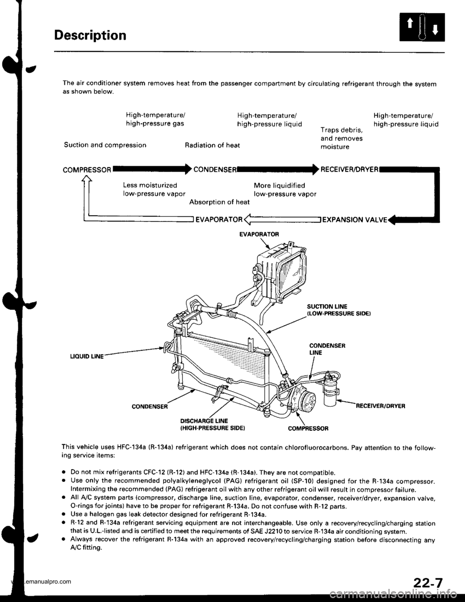
The air conditioner system removes heat from the passenger compartment by circulating refrigerant through the systemas shown below.
High'temperature/ High-temperature/
high-pressure gas h igh-pressure liquid
Suction and compression Radiation of heat
High-temperature/
high-pressu re liq uidr raps oeons,
and removes
motsture
More liquidified
row-pressure vapor
EVAPoRAToR (-l EXPANSToN vAL
SUCTION LINEtLow-PRESSURE S|OEt
LIOUID LINE
CONDENSER
coMpREssoR Il- coruoerusenl* necetve
Less moisturized
low-pressure vapor
Absorption of heat
DISCHARGE LINEIHIGH.PRESSURE SIDEI
This vehicle uses HFC-I34a (R-l34a) refrigerant which does not contain chlorofluorocarbons. Pay attention to the follow-ing service items:
. Do not mix refrigerants CFC-12 (R-12) and HFC-l34a (R-134a). They are not compatible.. Use only the recommended polyalkyleneglycol (PAG) refrigerant oil (SP-10) designed for the R-134a compressor.Intermixing the recommended (PAG) refrigerant oil with any other refrigerant oil will result in compressor failure.. Afl Ay'C system parts (compressor, discharge line. suction line, evaporator, condenser. receiver/dryer, expansion valve,O-rings for joints) have to be proper for refrigerant R-134a. Do not confuse with R-12 parts.
. Use a halogen gas leak detector designed for refrigerant R-134a.. R-12 and R-134a refrigerant servicing equipment are not interchangeable. Use only a recovery/recycling/charging stationthat is U.L.iisted and is certified to meet the requirements of SAE J2210 to service R-134a air conditioning system.. Always recover the refrigerant R-134a with an approved recovery/recycling/charging station before disconnecting anylVC fitting.
EVAPORAYOR
22-7
www.emanualpro.com
Page 1100 of 1395

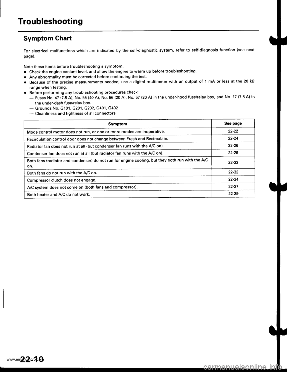
Troubleshooting
Symptom Ghart
For electrical malfunctions which are indicated by the self-diagnostic system, reter to selt-diagnosjs function (see next
page).
Note these items before troubleshooting a symptom.
. Check the engine coolant level, and allow the engine to warm up before troubleshooting.
. Anv abnormality must be corrected before continuing the test.
. Because of the precise measurements needed, use a digital multimeter with an output of 1 mA or less at the 20 kO
range when testing.
. Before performing any troubleshooting procedures check:
- Fuses No. 47 17.5 AJ, No. 55 (40 A), No. 56 (20 A), No. 57 (20 A) in the under-hood fuse/relay box, and No. 17 {7.5 A) in
the under-dash fuse/relay box.._ Grounds No. G101, G201, G202, G401, G4O2
- Cleanliness and tightness of all connectors
SymptomSse pags
Mode control motor does not run, or one or more modes are inoperative.
Recirculation control door does not change between Fresh and Recirculate.22-24
Radiator fan does not run at all (but condenser fan runs with the AVC on).
Condenser fan does not run at all {but radiator fan runs with the Ay'C on).22-29
Both fans (radiator and condenser) do not run for engine cooling. but they both run with the A,/C
on.
Both fans do not run with the Ay'C on22-33
Compressor clutch does not engage.22-34
AJC svstem does not come on (both fans and compressor).22-37
Both heater and A/C do not work,22-39
22-10
www.emanualpro.com