Page 160 of 1395

Piston PinsConnecting Rods
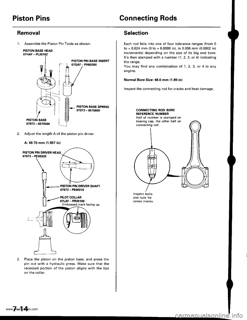
Assemble the Piston Pin Tools as shown.
PISTON BASE HEAO07HAF -PL20102
PISTON BASE07973 - 6570500
Adjust the length A of the piston pin dflver.
A: 49.70 mm 11.957 in)
PIN DRIVER HEAIPE00320
\
RIr1
nT---
u
ffi-"""-
u_ll
3. Place the piston on the piston base, and press the
pin out with a hydraulic press. Make sure that the
recessed portion of the piston aligns with the lips
on the collar.
7-14
Removal
1.
PISTON07973 -
PISTON PIN BASE INSERT07GAF - PH60300
PISTON PIN DRIVER SHAFT07973 - PEt 0310
PILOT COLLAR07LAF - PR30100Embossod mark facing up.
Selection
Each rod falls into one of four tolerance ranges (from 0
to + 0.024 mm {0 to + 0.0009 in). in 0.006 mm (0.0002 in)
increments) depending on the size of its big end bore.
lt's then stamped with a number 1.1.2,3, or 4) indicating
the range.
You may find any combination ot 1,2,3, or 4 in any
engrne.
Normal Bore Size: ,18.0 mm (1.89 in)
Inspect the connecting rod for cracks and heat damage.
CONNECTING ROD BOREREFENENCE NUMBERHalf of number is stamped onbearing cap, the other half onconnectno roo.
www.emanualpro.com
Page 161 of 1395
Piston Pins
lnstallation
The arrow must face thetiming belt side ot theengine and the connectingrod oil hole must face therear of the engine.
CONNECTING ROOotL Hor.E
1. Adjust the length B of the piston pin driver and shaft.
B: 49.70 mm (1.957 in)
PISTON PIN DRIVER SHAFT0t973 - P€qxtlo
Place the piston on the
pin in with a hydraulic
recessed portion of the
on the piston base head.
ffi*r,"ron'nl
PILOT COLLAROTLAF - PF3O1(x'
PISTON PIN BASE INSERT07GAF - PH6o3ttO
PISTON BASE HEADOTHAF - PL2O102
PISTON BASE07973 - 6670500
piston base and press the
press. Make sure that the
piston aligns with the lugs
7-15
www.emanualpro.com
Page 428 of 1395
Clutch
Speciaf Tools ....,..... ..........' 12-2
lllustrated lndex ........... .'." 12'3
Clutch Pedal
Adjustment ........."."."".12-4
Clutch Master Cylinder
RemovaUlnstallation '." 12'5
Slave Cylinder
Removal/lnstallation .'.. 12-6
Pressure Plate
RemovaUlnspection ..'." 12-7
Clutch Disc
Removal/lnspection ."'.. 12-8
Flywheel
Inspection ...................... 12-9
Replacement ....................................... 1 2-9
Clutch Disc, Pressure Plate
lnstallation ....................' 12-10
Release Bearing
Removal/lnspection ...... 12'11
lnstaflation ..................... 12-12
www.emanualpro.com
Page 429 of 1395
Special Tools
Rel. No. I Tool NumberDescriptionOty Page Reference
a
IA
@
!c,
Lo,
OTJAF - PM70,I1A
07NAF - PR30l00
07LAB - PV00100 or
07924 - PD20003
07746 0010100
07749 - 0010000
07936 - 3710100
Clutch Alignment Disc
Clutch Alignment Shaft
Ring Gear Holder
Attachment, 32 x 35 mm
Driver
Ha nd le
1 | t2-7
1 12-7 , A, '�t0, 11
1 12-7 ,9, 10, 1'l
I1 I 12-10
1 12-10
1 12-7 , a, 10, 11
b)
2-2
www.emanualpro.com
Page 437 of 1395
FlywheelClutch Disc, Pressure Plate
Replacement (cont'dl
Drive the new bearing
specialtools.
HANOLE DRIVER07749-
ATTACHMET{T-32x35mm07746 -O010100
FLYWHECI-
Align the hole in the flywheel with the crankshaft
dowel pin, and install the flywheel. Install the
mounting bolts finger-tight.
Install the special tool, then torque the flywheel
mounting bolts in a crisscross pattern in several
steps as shown.
Torque:12 x 1.0 mmr03 N.m (10.5 kgl.ln,75.9 tbtftl
into the flywheel using the
12-10
Installation
1. Install the ring gear holder.
CLUTCH ALIGNMENT SHAFT07NAF - PR30100
CLUTCH DISC
RING GEAR HOLDER07LAB _ pvoot(x) or07924 _ PD20003
Apply grease to the spline of the clutch disc, then
install the clutch disc using the special tools.
NOTE: Use only Super High Temp Urea Grease(P/N 08798 - 9002).
lnstall the pressure plate.
PRESSURE PLATE
www.emanualpro.com
Page 499 of 1395

Transfer Assembly
Reassembly (cont'd)
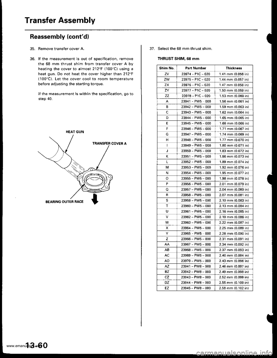
Remove transfer cover A.
lf the measurement is out of specification, remove
the 68 mm thrust shim from transfer cover A by
heating the cover to almost 212'F (100'C) using a
heat gun. Do not heat the cover higher than 212F
(100"C). Let the cover cool to room temperature
before adjusting the starting torque.
lI the measurement is within the specification, go to
step 40.
COVER A
BEARING OUTER RACE
35.
36.
HEAT GUN
13-60
37. Select the 68 mm thrust shim.
THRUST SHIM, 68 mm
Shim No.Part NumberThickne3s
zv23914-P1C-0201.41 mm (0.056 in)
zw23975-P1C-020'1.44 mm 10.057 in)
zx23916 PlC -020'1.47 mm (0.058 in)
ZI23917 -P1C-O201.50 mm (0.059 in)
zz23978-PlC-0201.53 mm (0.060 in)
23941 - PW5 0001.56 mm {0.061 in)
23942-PWs-0001.59 mm (0.063 in)
c23943-PW5-000't.62 mm (0.064 in)
D23944 PW5 - 0001.65 mm (0.065 in)
E23945-PWs-0001.68 mm (0.066 in)
F23946-PW5-0001.71 mm 10.067 in)
G23947-PW5-000'1.74 mm 10.069 in)
23948-PWs-0001.77 mm (0.070 in)
23949-PWs-0001.80 mm (0.071 in)
239s0-PW5-0001.83 mm (0.072 in)
K23951 - PW5 - 0001.86 mm (0.073 in)
L23952-PWs-0001.89 mm {0.074 in)
239s3-PWs-0001.92 mm {0.076 ini
N23954-PW5-0001.95 mm (0.077 in)
o23955-PW5-0001.98 mm (0.078 in)
P23956 - PW5 , 0002.01 mm (0.079 in)
o23957-PWs-0002.04 mm (0.080 in)
R23958-PWs-0002.07 mm (0.081 in)
23959-PW5-0002.10 mm (0.083 in)
T23960-PW5-0002.13 mm (0.084 in)
U23961 - PW5 - 0002.16 mm (0.085 in)
23962-PW5-0002.19 mm (0.086n)
23963-PWs-0002.22 mm (0.087n)
X23964-PWs-0002.25 mm (0.089n)
23965,PWs-0002.28 mm 10.090n)
23966-PW5-0002.31 mm {0.091 in)
23967-PWs-0002.34 mm (0.092 in)
AB23968-PWs-0002.37 mm (0.093 in)
AC23969-PWs-0002.40 mm {0.094 in}
AD23970-PW5-0002.43 mm (0.096 in)
M23941 - PW8 - 0002.46 mm {0.097 'n}
BZ23942-PW8-0002.49 mm (0.098 in)
cz23943-PW8-0002.52 mm {0.099 ini
DZ23944-PW8-0002.55 mm (0.100 in)
EZ23945-PW8-0002.58 mm (0.102 ini
www.emanualpro.com
Page 504 of 1395

78 mm SHIM
Part NumborThickness
23941 - P16 - 0001.20 mm (0.0472 in)
23942-P16-0001.23 mm (0.0484 in)
c23943-P16-000'1.26 mm (0.0496 in)
u23944-Pt6-0001.29 mm (0.0508 in)
23945-P16-0001.32 mm (0.0520n)
F23946- P16 - 0001.35 mm (0.0531n)
G23947-P16-0001.38 mm {0.0543n)
H23948-P16-0001.41 mm (0.0555n)
23949-P16-0001.44 mm (0.0567 in)
23950-P16-0001.47 mm (0.0579 in)
K23951 - P16 - 0001.50 mm {0.0591 in}
L23952-Pl6-0001.53 mm (0.0602 in)
M23953-P16-0001.56 mm (0.0614 in)
N23954-P16-0001.59 mm (0.0626 in)
o23955-P15-0001.62 mm (0.0638 in)
23956 - P16 - 0001.65 mm (0.0650 in)
23957-P16-0001.68 mm (0.066't in)
23958- P16 - 0001.71 mm (0.0673 in)
23959-P16-0001.74 mm {0.0685 in)
T23960-P16-0001.77 mm {0.0697 inl
23961 - P16 - 0001.80 mm (0.0709 in)
23962-P16-0001.83 mm (0.0720 in)
23963-P16-000'1.86 mm (0.0732 in)
X23964-P16-0001.89 mm (0.0744 in)
23965-P16-0001.92 mm (0.0756 in)
z23966-Pl6-0001.95 mm (0.0768 in)
23967-Pl6-0001.98 mm (0.0780 in)
AB23968-P16-0002.01 mm (0.0791 in)
23969-Pl6-0002.04 mm (0.0803 in)
AD23970 - Pl6-0002.07 mm {0.0815 in)
AE23971 - P16 - 0002.10 mm {0.0827 in}
23972-P16-0002.13 mm (0.0839 in)
23973-P16-0002.16 mm (0.0850 in)
AH23974-P16-0002.19 mm (0.0862 in)
AI23975-P16-0002.22 mm 10.087 4 inl
AJ23976-Pl6-0002.25 mm {0.0886 in}
AK23977-P16-0002.28 mm {0.0898 in)
23978-Pl6-0002.31 mm (0.0909 in)
23979-Pl6-0002.34 mm (0.0921 in)
AN23980-P16-0002.37 mm (0.0933 in)
7, Check the thrust clearance in the manner described
Delow.
NOTE: Measurement should be made at normal
room temperature.
-1. Install the 78 mm shim selected and oil guide
plate in the transmission housing.
78 mm SHIM
OIL GUIDE PLATE
Install the spring washer and washer on the
ball bearing.
NOTE:
. Clean the spring washer, washer and thrust
shim thoroughly before installation.
. Install the spring washer, washer and thrust
shim properly.
WASHER
g
,-g
SPRTNG*ASHER
Install the mainshaft in the clutch housing.
Place the transmission housing over the main-
shaft and onto the clutch housing.
Tighten the clutch and transmission housings
with several 8 mm bolts.
NOTE: lt is not necessary to use sealing agent
between the housings.
Tap the mainshaft with a plastic hammer.
-2.
-5.
(cont'd)
13-65
www.emanualpro.com
Page 518 of 1395

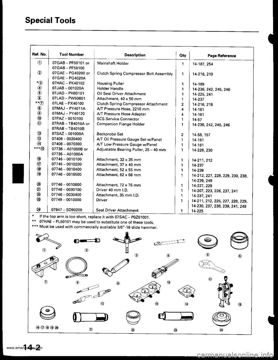
Ref. No.
^tl)
@
*rar
@
@
,-o
@
o
@
@
@
@
@.--@
@
@
@
@
@
@
@
@
@
Tool NumberDescriptionOty I Pago Referonc€
Mainshaft Holder
Clutch Spring Compressor Bolt Assembly
Housing Puller
Holder Handle
Oil Seal Driver Aftachment
Attachment, 40 x 50 mm
Clutch Spring Compressor Attachment
Ay'T Pressure Hose, 2210 mm
IVT Pressure Hose Adapter
SCS Service Connector
Companion Flange Holder
Backprobe Set
lVT Oil Pressure Gauge Set w/Panel
A,/T Low Pressure Gauge w/Panel
Adjustable Bearing Puller, 25 - 40 mm
Anachment, 32 x 35 mm
Attachment, 37 x 40 mm
Attachment. 52 x 55 mm
Attachment. 62 x 68 mm
Attachment, 72 x 75 mm
Driver 40 mm l.D.
Attachment, 35 mm LD.
Driver
07GAB - PF50101 or
07GAB - PF50100
07GAE - PG40200 or
OTGAE _ PG4O2OA
07HAC - PK40102
07JAB - 001020A
07JAD - PH80101
07LAD - PW50601
07LAE - PX40100
OTMAJ - PY4O114
07MAJ - PY40120
07 PAZ - 0010100
07RAB - TB4010A or
07RAB.TB40lOB
07sAz - 001000A
07406 - 0020400
07406 - 0070300
07736 - 4010008 or
07736 - A010004
07746 - 0010100
07746 - 0010200
07746 - 0010400
07746 - 0010500
07746 - 0010600
07746 - 0030100
07746 - 0030400
07749 - 0010000
07947 - SD90200Seal Driver Aftachment
1
1
1
1,l
1
I
2
1'l
1
I
1
1
1
1
1
1
I
1
14-181 , 254
14-216,219
14-189't4-236,242,245,246
't 4-225, 241
14-237
14-216,2't9
14-161
14- 161
14-57
14-236,242,245,246
14-58, 157
14-161
14-161'14-229,230
14-211, 2't2
14-231
14-239
14-212, 227 , 228,229, 230, 238,
14-239, 249
14-221 ,229't 4-207 , 223,226, 237 , 241
14-237,241
1 +21 1, 2't2, 225, 227, 228, 229,
14-230, 237 , 238, 239, 24't, 249't4-225
lf the top arm is too short, replace it with 07SAC - pOZ01OO1.
07HAE - PL50101 may be used to substitute one of these tools.Must be used with commercially available 3/8"-16 slide hammer.
E----G
@@@@@
@
tvj
'
@@@)
14-2
www.emanualpro.com