Page 845 of 1395
Propeller Shaft
RemovaUlnstallation
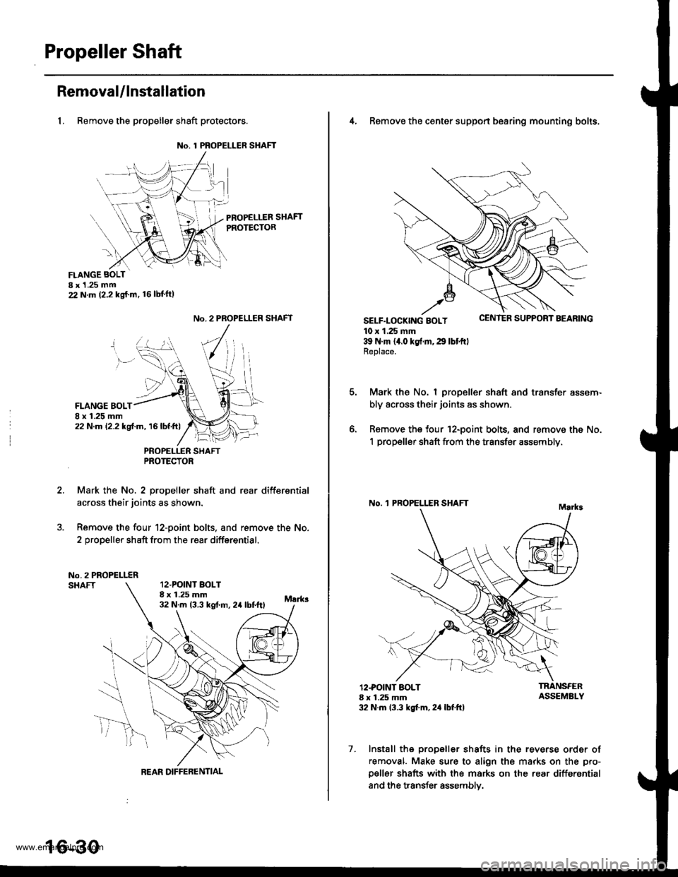
1, Remove the propeller shaft protectors.
No. 1 PROPELLER SHAFT
PROPELLER SHAFTPROTECTOR
FLANGE BOLTI x 1 .25 mm22 N.m (2.2 kg{.m. 16lbl'ft)
2.
No. 2 PROPELLER SHAFT
FLANGE BOLT8 x 1.25 mm22 N.m 12.2 kgf.m, 16lbf.ft)
PNOPELLER SHAFTPROTECTOR
Mark the No. 2 propeller shaft and rear differsntial
across their joints as shown.
Remove the four 12-point bolts. and remove the No.
2 propeller shaft from the rear differential.
No.2 PROPELLERSHAFT12.POINT BOLT8 x 1.25 mm32 N.m 13.3 kst m, 24 lbtftl
REAR DIFFERENTIAL
16-30
4, Remove the center support bearing mounting bolts.
SELF-LOCK|NG BOLT uErr rEn Durrr.r'r I I'EAnrNu
10 x 1.25 mm39 N'm 14.0 kg{.rn,29 lbtftlReplace.
Mark the No. I propeller shaft and transfer assem-
bly across their joints as shown.
Remove the four 12-point bolts, and remove the No.
1 propeller shaft from the transfer assembly,
No. 'l PROPELLER SHAFT
o.
12.POINT BOLT8 x 1.25 mm32 N.m 13.3 kgt'm, 2,1 lbf.ft)
TRANSFERASSEMBLY
7. Install the propeller shafts in the reverse order of
removal. Make sure to align the marks on the pro-
p€ller shafts with the marks on the rear differential
and the transfer assemblv.
www.emanualpro.com
Page 848 of 1395
Component Locations
lndex
Note these items during disassembly:' lf an intact airbag assembly has been removed from a scrapped vehicle or has been found defective or damaged dur-ing transit, storage or service. it should be deployed (see section 24),a Before removing the gearbox, remove the driver.s airbag assembly and steering wheel.. After installing the gearbox, check the wheel alignment and adjust if necessary.
SRS components are located in this area. Review the SRS component locations, precautions, and procedures an the SRssection (24) before performing repairs or servrce.
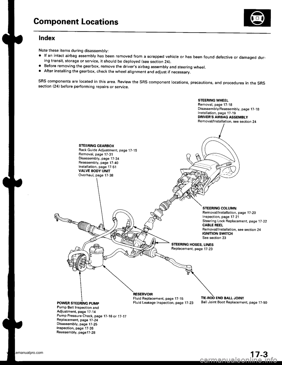
STEERING WHEELRemoval, page 17,18Disassembly/Reassembly, page 1?,18Installation, page 17-19DRIVER'S AIRBAG ASSEMBLYRemoval/lnstallation, see section 24
STEERING GEARBOXRack Guide Adjustment, page 17-15Removal, page 17-31Disassembly, page 17-34Reassembly, page 17,40Installation, page 17,51VALVE BODY UNITOverhaul, page 17-38
STEERING COLUMNRemoval/lnstallation. page 17-20Inspection, page l7 21Steering Lock Replacement, page 17 22CABLE REELRemoval/lnstallation, see section 24tcNrnoN swtTcHSee s€ction 23
STEERING HOSES, LINESReplacement. page l7-23
Pump Belt Inspection andAdjustment, pag€ t7-14Pump Pressure Check, page 17-16 ot 17-1jReplacemont, page 17-24Disassembly, pa96 17,25Inspection, page 17-26Reassembly. page17-28
RESERVOIRFluid R6placement. page 17 15Fluid Leakage lnspection, page 17-23
END BALL JOINTBallJoint Boot Replacement, page 17-50
17-3
www.emanualpro.com
Page 853 of 1395
Troubleshooting
Noise and Vibration
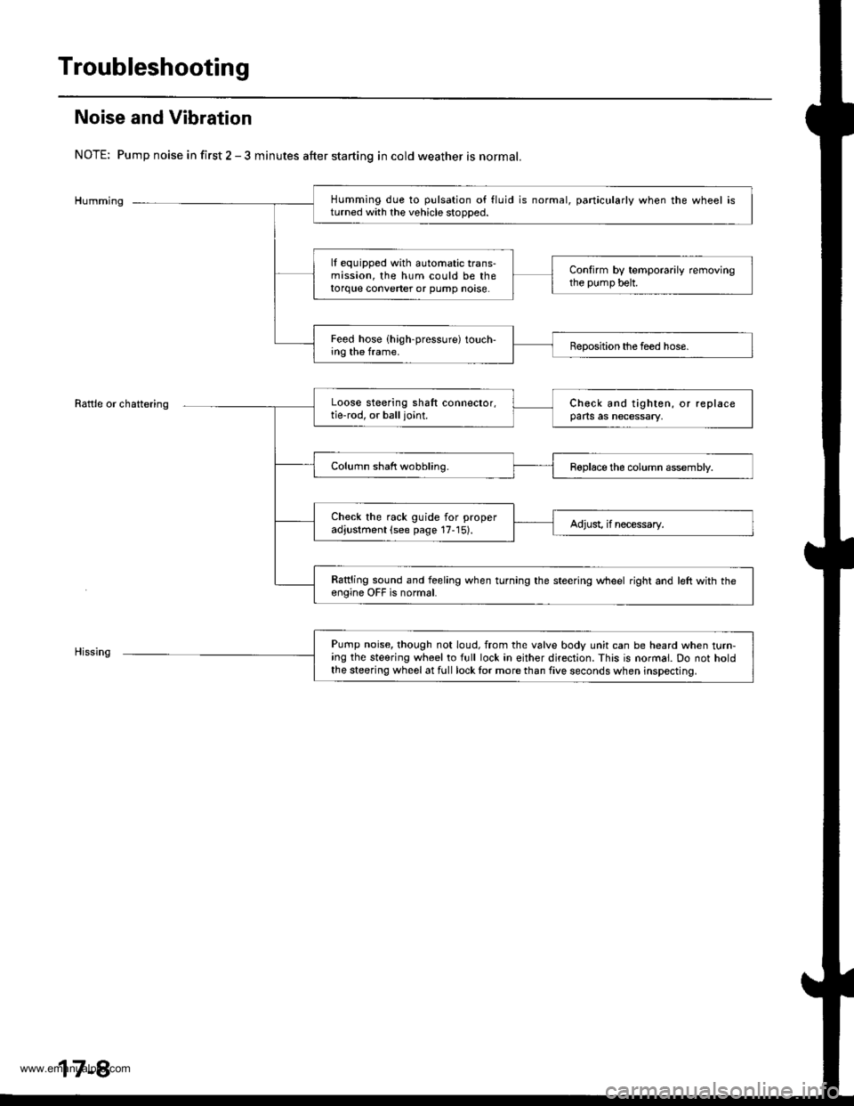
NOTE: Pump noise in first 2 - 3 minutes after starting in cold weather is normal.
Humming
Rattle or chattering
Humming due to pulsation of fluid is normal, particularly when the wheel isturned with the vehicle stooDed.
lf equipped with automatic trans-mission, the hum could be thetorque converter or pump noase.
Confirm by temporarily removingthe pump belt.
Feed hose (high-pressure) touch-ing the frame.Beposition the feed hose.
Loose steering shaft connector,tie-rod, or balljoint.Check and tighten, or replaceparts as necessary,
Column shaft wobbling.Roplace the column assembly.
Check the rack guide for properadjustment (see page 17-15).Adjust, if necessary.
Rattling sound and feeling when turning the steering wheel right and left with th€engine OFF is normal.
Pump noise, though not loud, from the valve body unit can be heard when turn-ing the steering wheel to full lock in either direction. This is normal. Do not holdthe steering wheel at full lock lor more than five seconds when inspecting.
17-8
www.emanualpro.com
Page 860 of 1395
Rack Guide Adjustment
1.
6.
7.
5.
4.
Set the wheels in the straight ahead position.
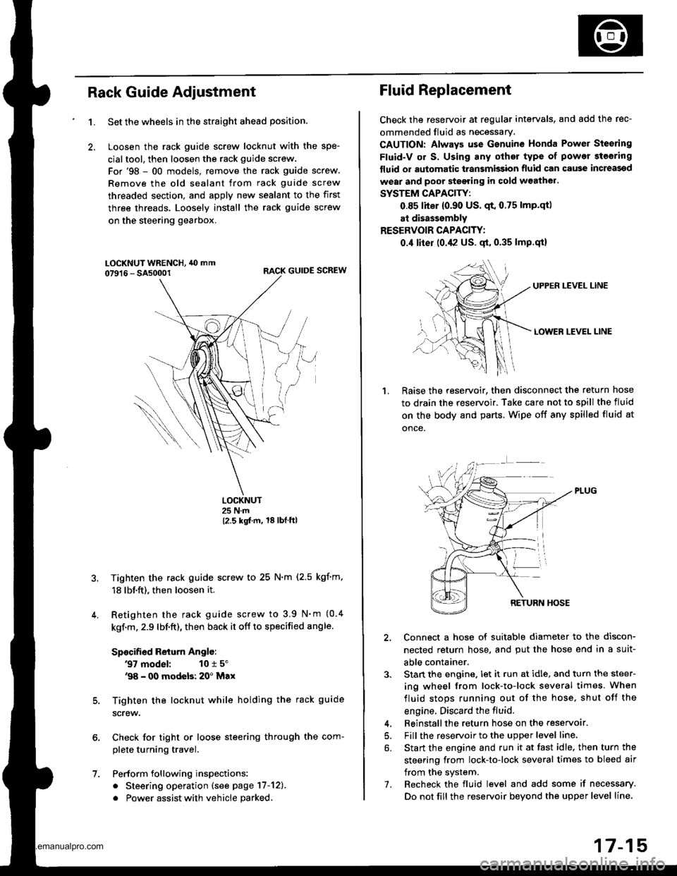
Loosen the rack guide screw locknut with the spe-
cialtool, then loosen the rack guide screw.
For'98 - 00 models, remove the rack guide screw.
Remove the old sealant from rack guide screw
threaded section, and apply new sealant to the first
three threads. Loosely install the rack guide screw
on the steering gearbox.
RACK GUIDE SCREW
LOCKNUT25 N.m
12.5 kgt m, 18lbtftl
Tighten the rack guide screw to 25 N.m (2.5 kgf'm,
18 lbf.ft), then loosen it.
Retighten the rack guide screw to 3.9 N'm (0.4
kgf.m, 2.9 lbf.ft), then back it off to specified angle.
Specified Return Anglo:
37 model: 10 r 5"'98 - 00 modeb: 20' Max
Tighten the locknut while holding the rack guide
screw.
Check for tight or loose steering through the com-
plete turning travel.
Perform following inspections:
. Steering operation (see page 17-12).
. Power assist with vehicle parked
Fluid Replacement
Check the reseryoir at regular intervals, and add the rec-
ommended fluid as necessary.
CAUTION: Always use Gsnuine Honda Power Steering
Fluid-V or S. Using any other type of power steering
tluid or automatic transmission fluid can cause increassd
wear and poor steering in cold w3athel.
SYSTEM CAPACITY:
0.85 liter {0.90 US. qt. 0.75 lmp.qtl
at disasssmbly
RESERVOIR CAPACITY:
0.,1 liter (0.42 US. gt, 0.35 lmp.qi)
UPPEN LEVEL LINE
LOWER LEVEL LINE
1.Raise the reservoir. then disconnect the return hose
to drain the reservoir. Take care not to spill the fluid
on the body and parts. Wipe off any spilled fluid at
once.
2, Connect a hose of suitable diameter to the discon-
nected return hose, and put the hose end in a suit-
able container.
3. Stan the engine. let it run at idle, and turn the steer-
ing wheel from lock-to-lock several times. When
fluid stops running out of the hose, shut off the
engine. Discard the fluid.
4. Beinstallthe return hose on the reservoar.
5. Fill the reservoir to the upper level line,
6. Start the engine and run it at fast idle. then turn the
steering from lock-to-lock several times to bleed air
from the system.
7. Recheck the fluid level and add some if necessary.
Do not fill the reservoir beyond the upper level line.
www.emanualpro.com
Page 876 of 1395
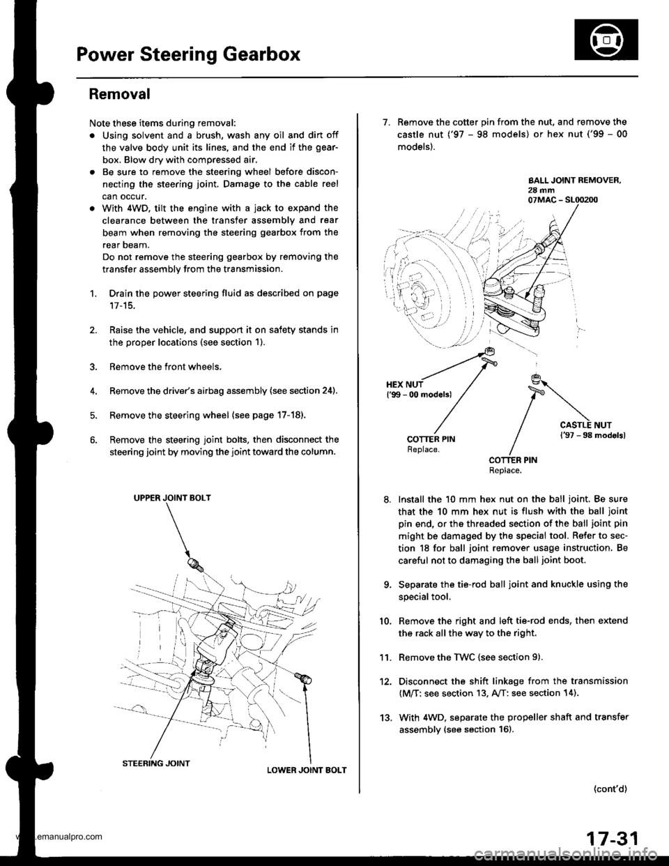
Power Steering Gearbox
Removal
Note these items during removal:
. Using solvent and a brush, wash any oil and dirt off
the valve body unit its lines, and the end if the gear-
box. Blow dry with compressed air.
. Be sure to remove the steering wheel before discon-
necting the steering joint. Damage to the cable reel
can occur.
. With 4WD. tilt the engine with a jack to expand the
clearance between the transfer assembly and rear
beam when removing the steering gearbox from the
rear oeam.
Do not remove the steering gearbox by removing the
transfer assembly from the transmission.
1. Drain the power steering fluid as described on page'17-15.
Raise the vehicle, and suppon it on safety stands in
the proper locations (see section 1).
Remove the front wheels,
Remove the drive/s airbag assembly {see section 24).
Remove the steering wheel {see page 17-18).
Remove the steering joint bolts, then disconnect the
steering joint by moving the joint toward the column.
UPPER JOINT BOLT
LOWER JOINT BOLT
13.
7. Remove the cotter pin from the nut, and remove the
castle nut {'97 - 98 models) or hex nut ('99 - 00
models).
COTTER PINReplace.
Install the 10 mm hex nut on the ball joint. Be sure
that the 10 mm hex nut is flush with the ball joint
pin end, or the threaded section of the ball joint pin
might be damaged by the special tool. Refer to sec-
tion 18 for ball joint remover usage instruction, Be
careful not to damaging the ball joint boot.
Separate the tie-rod ball joint and knuckle using the
special tool.
Remove the right and left tie-rod ends, then extend
the rack all the way to the right.
Remove the TWC (see section 9).
Disconnect the shift linkage from the transmission
(M/T: see section 13, A/T: see section 14).
With 4WD. separate the propeller shaft and transfer
assembly (see section 161.
10.
11.
(cont'd)
17-31
www.emanualpro.com
Page 877 of 1395
Power Steering Gearbox
AN'USTABLE HOSE CLAMP
Removal (cont'dl
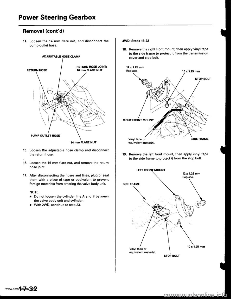
14. Loosen the 14 mm flare
pump outlet hose.
nut, and disconnect the
14 mm FLARE NUT
15. Loosen the adjustable hose clamp and disconnect
the return hose,
16. Loosen the 16 mm flare nut, and remove the return
hose joint.
17. After disconnecting the hoses and lines, plug or seal
them with a piece of tape or equivalent to prevent
foreign maisrials from entering the valve body unit.
NOTE:
. Do not loosen the cylinder line A and B between
the valve body unit and cylinder.
. With 2WD, continue to step 23.
17 -32
STOP BOLT
10 x 1.25 mm
4WD: Stepr 18-22
18. Removethe right tront mount, then apply vinyl tape
to the side frame to protect it from the transmission
cover and stop bolt.
12 x 1.25 fiiAReplace.
RIGHT FRONT MOUNT
x 1,25 mm
SIDE FRAME
'19. Remove the left front mount, then apply vinyl tape
to the side frame to protect it from the stop bolt.
Vinyltape orequivalgnt material.
Vinyltap€ orequival€nt m6terial.
www.emanualpro.com
Page 878 of 1395
REAR MOUNT
20. Remove the rear mount bracket and rear mount.
12 x 1.25 mmReplace.
REAR MOUNT BRACKET12 x 1.25 mmReplace.
21.
14 x 1.5 mmReplaco.
Place a jack under the engine block in the area
shown,
?*
JACK.UP POINT
17-33
22. Jack up the engine and tilt the engine back until the
transfer assembly is lowered approximately 40 mm
(1.57 in).
Note these items when tilting the engine:
. Check that the wire harnesses, hoses and pipes
are not caught by any surrounding parts.
. Do not tilt the engine more than necessary.
ASSEMBLY
Remove the stiffener olate.
NOTE: Some stiffener plate mounting bolts a.e also
used as gearbox mounting bolts. The gearbox will
tilt to the side when these bolts are removed.
(cont'd)
.Lower approximately'40 mm (1.57 in)
STIFFENER PLATE
www.emanualpro.com
Page 879 of 1395
Power Steering Gearbox
Removal (cont'dl
24. Remove the mounting brackets.
25.lvlove the steering gearbox to the right so the
rack end clears the rear beam, then place the
rack end below the rear beam.
left
left
Move the steering gearbox to the left, and tilt the
left side down to remove it.
With 4WD. remove the steering gearbox through
the clearance between the transfer assembly and
propeller shaft.
MOUNTING BRACKETS
STEEBING GEARBOX
17 -34
4. Pull the boots away from the ends of the gearbox.
Disassembly
Steering Rack Disassembly
Note these items when disassembling:
. Before disassembling the gearbox, wash it off with
solvent and a brush.
. Do not dip seals and O-rings in solvent.
1. Remove the steering gearbox (see page 17-31).
2. Remove airtube and clips.
3. Remove the boot bands and tie-clips.
AIR TUBE
www.emanualpro.com