Page 55 of 1395

Starting System
Starter Test
NOTE: The air temperature must be between 59 and'100'F (15 and 38"C) before testing.
Recommended Procedure:
. Use a staner system tester.
. Connect and operate the equipment in accordance
with the manufacturer's instructions.
. Test and troubleshoot as described.
Alte.nate Procedure:
. Use the following equipment:- Ammeter, 0 - 400 A- Voltmeter, 0 - 20 V (accurate within 0.1 volt)
Tachometer,0 - 1,200 rpm
. Hook up a voltmeter and ammeter as shown.
NOTE: After this test, or any subsequent repair. reset
the ECM/PCM to clear any codes (see section 1 1).
Check the Starter Engagement:
'1. Remove the No. 44 (15 A) fuse from the under-hood
fuse/relay box.
2. Turn the ignition switch to START (lll) with the shift
lever in E or E position (A/T) or with the clutch
pedal depressed {M/T). The starter should crank the
eng ine.
. lf the starter does not crank the engine, go to
step 3.
. lf it cranks the engine erratically or too slowly, go
to "Check for Wear and Damage" on the next
page.
NEGATIVE TERMINAL
4.
5.
6.
7.
8.
Check the battery, battery positive cable, ground.
staner cut relay, and the wire connections for loose-
ness and corrosion. Test again.
lf the staner still does not crank the engine, go to
step 4.
Unplug the connector (BLK /VHT wire and solenoid
terminal) from the starter.
Connect a jumper wire from the baftery positive (+)
terminal to the solenoid terminal.
The starter should crank the engine.
. lf the starter still does not crank the engine,
remove it, and diagnose its internal problem.
. lf the starter cranks the engine, go to step 6.
Check the ignition switch (see section 23).
Check the starter cut relay {see section 23}.
Check the IVT gear position switch (A/T) or the clutch
interlock switch (M[).
Check for an open in the wire between the ignition
switch and starter.
(cont'd)
4-5
www.emanualpro.com
Page 60 of 1395
Starting System
Armature Inspection and Test
1. Inspect the armature for wear or damage due to
contact with the field winding. lf there is wear or
damage. replace the armature.
Check the commutator surface. lf the surface is dirty
or burnt, resurface with emery cloth or a lathe with-
in the tollowing specifications, or recondition with
#500 or #600 sandDaoer.
lnspect for damage.
4-10
3. Check the commutator diameter. lf commutator
diameter is below the service limit, reolace the
armalure.
Commutator Diameter
Standard (Newl: 27.9 - 28.0 mm (1.09 - 1.10 in)
Service Limilr 27.0 mm (1.06 inl
lf the commutator runout is within the service
limit, check the commutator for carbon dust or
brass chips between the segments.
lf the commutator runout is not within the ser-
vice limit, replace the armature.
Commutator Runout
Standard (Newl: 0 - 0.02 mm (0 - 0.0008 in)
Service Limit: 0.05 mm {0,002 inl
4. Measure the commutator runout.
www.emanualpro.com
Page 61 of 1395
I
NOT GOOD
5. Check the mica depth. lf necessary, undercut the
mica with a hacksaw blade to achieve proper depth.
lf the service limit cannot be maintained, reDlace
the armature.
MICA DEPTI{
Commutator Mica Depth
Standard (Nsw): 0.5 - 0.8 mm 10.02 - 0.03 inl
Servico Limit: 0.2 mm (0.008 in)
Check for continuity between the segments of the
commutator. lf an open circuit exists between any
segments. replace the armature.
6.
COMMUTATOR
4-11
7. Place the armature on an armature tester. Hold a
hacksaw blade on the armature core.
lf the blade is attracted to the core or vibrates while
the core is turned. the armature is shorted. Replace
the armature.
8. With an ohmmeter, check that no continuity exists
between the commutator and armature coil core,
and between the commutator and armature shaft. lf
there is continuity. replace the armature,
cotL coRE
www.emanualpro.com
Page 64 of 1395
lgnition System
Component Location Index
IGNITION TIMING CONTROL SYSTEM
. ldle speed Inspection/Adjustment, section 11
. Inspection and Sening. page 4-16
DISTRIBUTORReplacement, page 4-17Overhaul, page 4-18lgnition CoilTest, page 4,20lgnition Control Module CM)Input Test, page 4,19
SERVICE CHECK CONNECTOR (2P)
lwi.c colo6: BRN rnd BLKI
TEST TACHOMETER
SPARK PLUGSInspection, page 4-21
WIRES
4-14
Inspection and Test, page 4-20
www.emanualpro.com
Page 65 of 1395
Circuit Diagram
IGNIT ONSW TCHUNDEF,DASHFUSEi RELAY BOX
6 l;;l Eci,.pcMi{Hr6-(-\9-'-'*'.--EII
V'il
IGN TIONW]BES
SPARKPLUGS
I l: '99 - 00 modelsGt01
4-15
UNDEF.HOOD FUSE/RELAY 8OX
f l-- r
TDC Top dead cenlerCKP Cran[shan poslionCYP Cylnder posrlon
TDC/CKP/CYP SENSOR
BLK/YEL
l^IGNITIONcotL
IGN]TION CONTROLMODULE (CM)
/ Has buil-if \I no|se l
i l' i--, -BLUll
ifrI BLU BLU I
ll/' i
| | resrI TACHOMETER
I I
tott"to*
LTTCHoMEIEB j'97 -'98 models
IJltfi--cMFcr,r
I
www.emanualpro.com
Page 69 of 1395

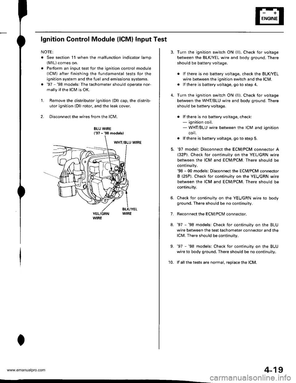
lgnition Control Module (lCMl Input Test
NOTE:
. See section 11 when the malfunction indicator lamp(MlL) comes on.
. Perform an input test for the ignition control module(lCM) after finishing the fundamental tests for the
ignition system and the fuel and emissions systems.
. '97 -'98 models: The tachometer should operate nor-
mally if the ICM is OK.
L Remove the distributor ignition (Dl) cap, the distrib-
utor ignition (Dl) rotor, and the leak cover.
2. Disconnect the wires from the lCM.
8LU WIRE{'97 - '98 models}
4-19
7.
Turn the ignition switch ON {ll). Check for voltage
between the BLK,^/EL wire and body ground. There
should be battery voltage.
. lf there is no battery voltage, check the BLK/rEL
wire betlveen the ignition switch and the lclvl.
. lf there is baftery voltage, go to step 4.
Turn the ignition switch ON (ll). Check for voltage
between the WHT/BLU wire and body ground. There
should be battery voltage.
. lf there is no batteryvoltage, check:- ignition coil.- WHT/BLU wire between the ICM and ignition
corl.
. lf there is battery voltage, go to step 5,
'97 model: Disconnect the ECM/PCM connector A(32P). Check for continuity on the YEL/GRN wire
between the ICM and ECM/PCM. There should be
continuity.'98 - 00 models: Disconnect the ECM,PCM connector
B (25P). Check for continuity on the YEUGRN wire
between the ICM and ECM/PCM. There should be
continuity.
Check for continuity on the YEUGRN wire to body
ground. There should be no continuity.
Reconnect the ECM/PClvl connector.
'97 -'98 models: Check for continuity on the BLU
wire between the test tachometer connector and the
lCM. There should be continuity.
'97 -'98 models: Check for continuity on the BLU
wire to body ground. There should be no continuity.
lf all the tests are normal, replace the lCM.
9.
'10.
www.emanualpro.com
Page 70 of 1395
lgnition System
lgnition Coil Test
Using an ohmmeter, measure resistance between the
terminals. lf the resistance is not within sDecifications,
replace the ignition coil.
NOTE: Resistance will vary with the coil temperature;
specifications are at 68"F (20'C).
Plimary Winding Resistance
{Between the A and B terminals):
0.6it - 0.77 0
Secondary Winding Resistance
{Between the A and secondary winding terminals):
12.8 - 19.2 kO
TERMINAL A {+l
4-20
eo
lgnition Wire Inspection and Test
1.Carefully remove the ignition wires by pulling on
the rubber boots. Do not bend the wires; you might
break them inside.
Check the condition of the ignition wire terminals. lf
any terminal is corroded, clean it, and if it is broken
or distorted, replace the ignition wire.
IGNITION WIRE
Connect the ohmmeter probes and measure resis-
tance.
lgnition Wire Resistance:
25 kO max. at 68'F 120'Cl
IGNITION WIRE
4. lf the resistance exceeds 25 kO, replace the ignition
wire.
www.emanualpro.com
Page 76 of 1395

Charging System
Troubleshooting (cont'dl
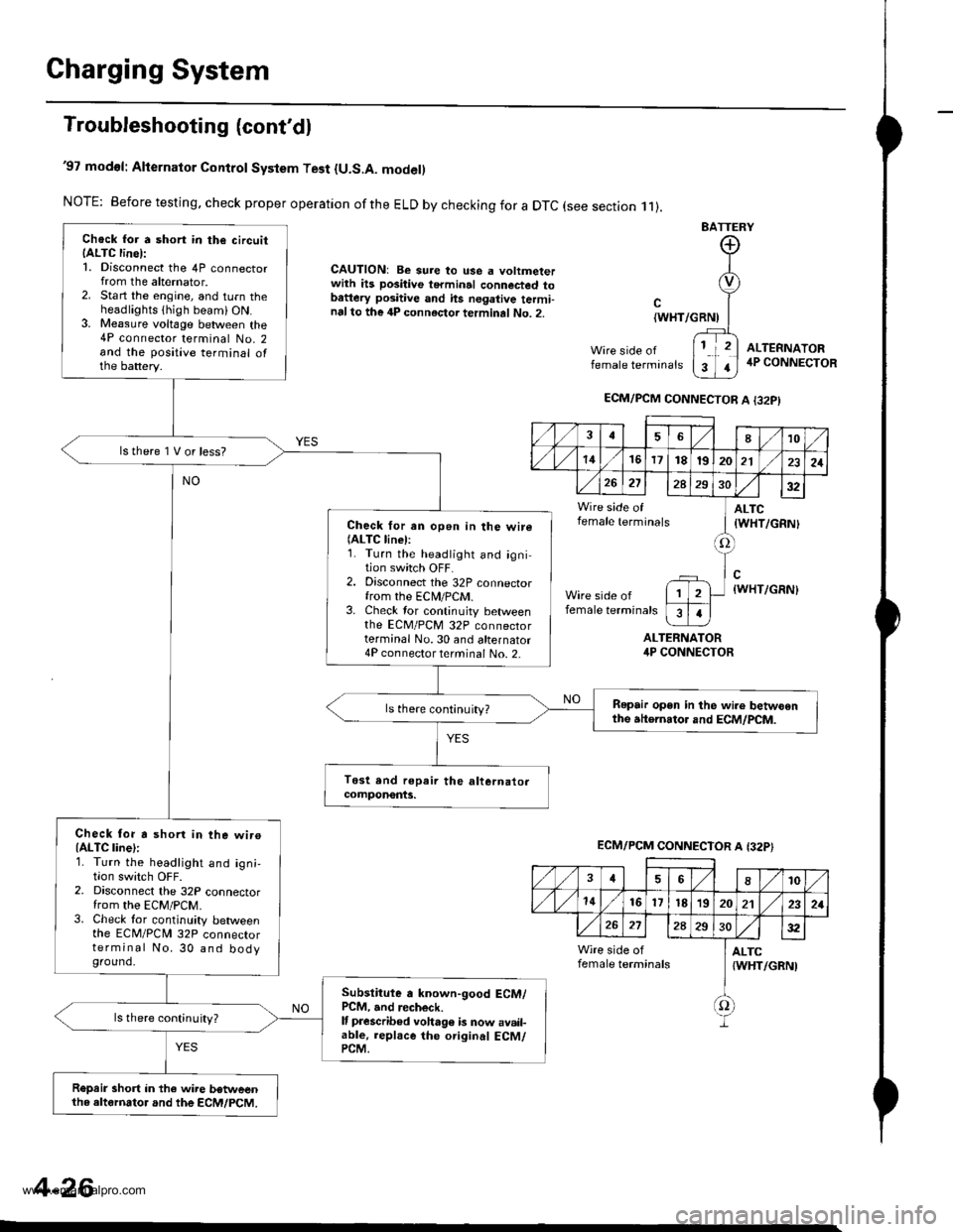
'97 modol: Alternator Control System Test {U.S.A. model)
NOTE: Before testing, check proper operation ofthe ELD by checking for a DTC (see section .11).
CAUTION: Be sure to use a voltmeterwith ils positive terminal connected tobattery positive and hs negative termi-nalto the 4P connector terminal No. 2.
BATTERY
Wire side offemale terminals
{WHT/GRNI
ALTERNATORirP CONNECTOR
ALTEFNATOR4P CONNECTOR
Chock for a short in the circuitIALTC line):1. Disconnect the 4P connectorfrom the alternator.2. Start the engine, and turn theheadlights thigh beami ON.3. Me8sure voltage between the4P connector terminal No. 2and the positive terminal ofthe battery.
lstherelVorless?
Check for an open in the wire(ALTC linel:1. Turn the headlight and igni-tion switch OFF.2. Disconnect the 32P connectorfrom the ECN4/PCM.3. Check tor continuity betweenthe EcM/PcM 32P connectorterminal No.30 and alternator4P connector terminal No. 2-
Repair open in the wi.e betwoenthe atternator and ECM/PCM.ls there continuity?
Check for a shorl in the wiroIALTC line):1. Turn the headlight and ign;,I|on swrtcn UFF2. Disconnect the 32P connectorfrom the EcM/PcM.3. Check tor continuity betweenthe ECM/PCN4 32P connectorterminal No. 30 and bodyground.
Subslitute a known-good ECM/PCM, and recheck.It prescribed voha96 b now avail-able, replace the original ECM/PCM.
ls there continuity?
R€prir short in the wire betweenthe altornator and the ECM/PCM.
ECM/PCM CONNECTOR A I32PI
,/1./1810
./ l./t4161718t9202121
26272A293032
Wire side of ] ALTCfemale terminals I tWHT/cRNl
tlWHT/GRN)
female terminals
I
1
ECM/PCM CONNECTOR A {32P}
,/ ,/46810
,/1,/1416l7t8'1920212321
272A2S30:t2
Wire side of I ALTCfemale terminals {WHT/GRNI
f)
4-26
www.emanualpro.com