Page 78 of 1395
Gharging System
Troubleshooting (cont'd)
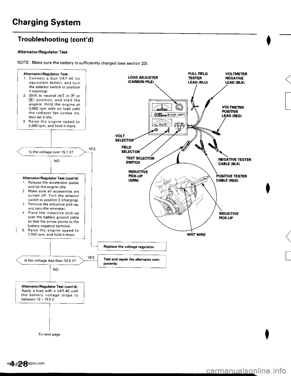
Alternator/Regulator Test
NOTE: Make sure the battery is sufficiently charged (see section 23).
FIELDSELECTOR
TESTswtTcH
I
VOLTMEIERPOSmVEt
NEGATIVE TESTERCABI.E {BLKI
(BED)
TESTERINDUCTIVEPICK.UP{GRN)CABLE IREDIAhernator/Regulator Test (cont'd)lI� Release the accelerator pedal,and let the engine idle.2 Make sure all accessories areturned off. Turn the selectorswitch to posjtion 2 (charging).3 Remove the inductive pick up,and zero the ammeter.{ Place the inductive pick-upover the battery ground cableso that the arrow points to thebaftery negative terminal.5. Raise the engine speed to2 000 rpm, and hold ir there.
I
(
T
I
WHT WIRE
Alternator/Regulator Test:1. Connect a Sun VAT-40 (orequrvalent tester), and turnthe selector switch to position1{sraning).2. Shift to neutral (A/T in E orN) position, and start theengane. Hold the engine at3,000 rpm with no load untilthe radiator fan comes on,then let it idle.3. Raise the engine speed to2,000 rpm, and hold it there.
ls the voltage over 15.1 V?
ls the voltage less than 13.5 V?
Altarnator/Regulator Test (cont'd:Apply a load with a VAT-40 untilthe battery voltage drops tobetween 12 - 13.5 V.
To next page
4-28
www.emanualpro.com
Page 82 of 1395
Charging System
IRectifier Test
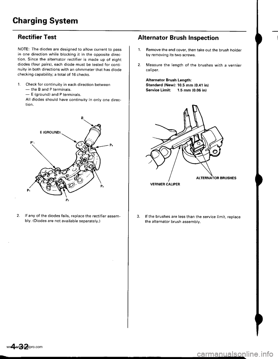
NOTE: The diodes are designed to allow current to pass
in one direction while blocking it in the opposite direc
tion. Since the alternator rectifier is made up of eight
diodes (four pairs), each diode must be tested for continuity in both directions with an ohmmeter that has diode
checking capability; a total of 16 checks.
'l. Check for continuity in each direction between- the B and P terminals.- E (ground) and P terminals.
All diodes should have continuity in only one direc-
tion.
2. lf any of the diodes fails, replace the rectifier assem-
bly. (Diodes are not available separatelv.)
4-32
1.
Alternator Brush Inspection
2.
Remove the end cover, then take out the brush holder
by removing its two screws.
Measure the length of the brushes with a vernier
calrper.
Alternator Brush Length:
Standard (Newl:10.5 mm 10.41 inl
Service Limit: 1.5 mm {0.06 in)
lf the brushes are less than the service limit, replace
the alternator brush assemblv.
VERNIER CALIPER
www.emanualpro.com
Page 118 of 1395
Valve Seals
Replacement (cylinder head removal not required)
The procedure shown below applies when using the in-
car valve spring compressor (Snap-on YA8845 with
YA8845-2A 7/8" auachment). Use approved eye protec-
tion.
1. Turn the crankshaft so that the No. 1 and the No. 4
pistons are at top dead center (TDC).
2. Remove the cylinder head cover.
3. Remove the distributor.
4. Loosen and disconnect the timing belt from the
camshaft pulleys.
5. Remove the camshaft holder bolts. then remove the
camshaft holders, the camshafts and rocker arms.
lntake Valve Seals
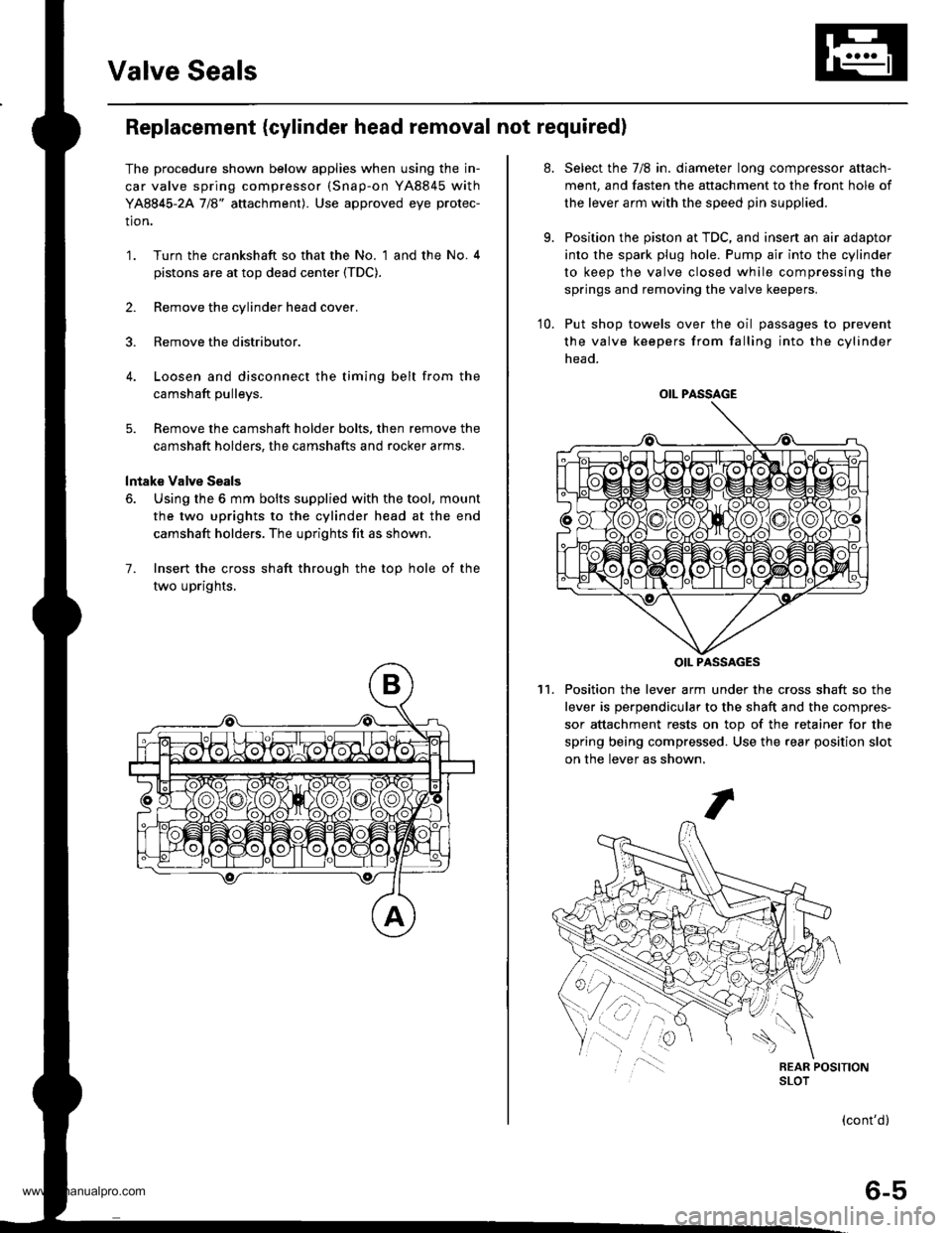
6. Using the 6 mm bolts supplied with the tool, mount
the two uprights to the cylinder head at the end
camshaft holders. The uprights fit as shown.
7. Insert the cross shaft through the top hole of the
two uprights,
at.
9.
Select the 7/8 in. diameter long compressor attach-
ment, and fasten the attachment to the front hole of
the lever arm with the speed pin supplied.
Position the piston at TDC, and insen an air adaptor
into the spark plug hole. Pump air into the cylinder
to keep the valve closed while compressing the
springs and removing the valve keepers.
10. Put shop towels over the oil passages to prevent
the valve keepers from falling into the cylinder
head.
Position the lever arm under the cross shaft so the
lever is perpendicular to the shaft and the compres-
sor attachment rests on top of the retainer for the
spring being compressed. Use the rear position slot
on the lever as shown,
't1.
OIL PASSAGE
OIL PASSAGES
(cont'd)
6-5
www.emanualpro.com
Page 119 of 1395
Valve Seals
12.
Replacement (cylinder head removal not requiredl (cont'dl
Using an upward motion on the lever arm, compress
the valve spring and remove the keepers from the
valve stem. Slowly release pressure on the spring.
Repeat step 11 for the other valve in that cylinder.
Remove the valve seals (see page 6-24).
Installthe valve seals (see page 6-29).
lnstall the springs, the retainers and the keepers in
reverse order of removal.
'17. Repeat steps 9 to 16 for the other three cylinders.
Exhaust valve Seals
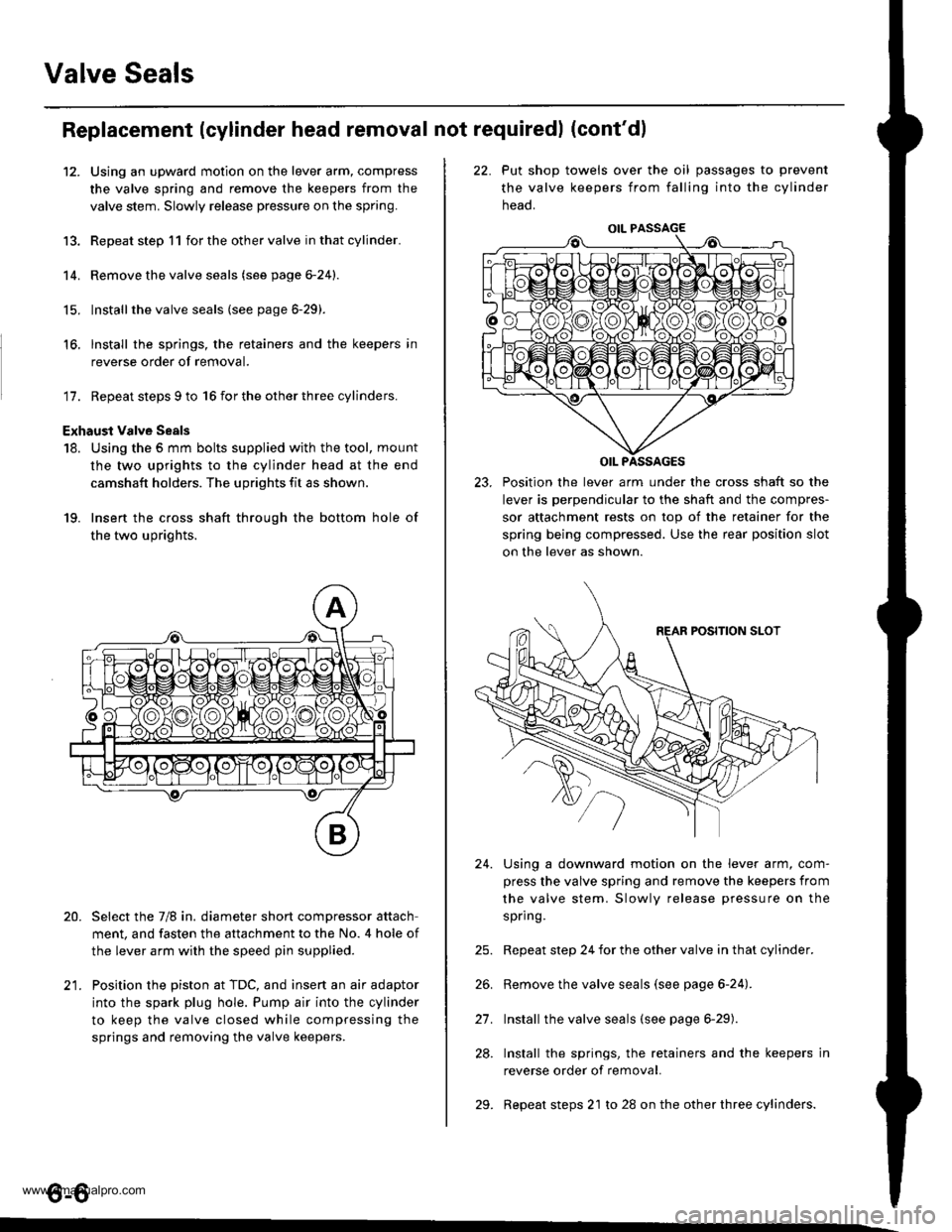
18. Using the 5 mm bolts supplied with the tool, mount
the two uprights to the cylinder head at the end
camshaft holders. The uprights fit as shown.
19. Insert the cross shaft through the bottom hole of
the two uprights.
Select the 7/8 in. diameter short compressor attach
ment, and fasten the attachment to the No. 4 hole of
the lever arm with the speed pin supplied.
Position the piston at TDC, and insert an air adaptor
into the spark plug hole. Pump air into the cylinder
to keep the valve closed while compressing the
springs and removing the valve keepers.
13.
14.
15.
16.
20.
t1
22. Put shop towels over the oil passages to prevent
the valve keepers from falling into the cylinder
neao.
23. Position the lever arm under the cross shaft so the
lever is perpendicular to the shaft and the compres-
sor attachment rests on top of the retainer for the
spring being compressed. Use the rear position slot
on the lever as shown.
Using a downward motion on the lever arm, com-
press the valve spring and remove the keepers from
the valve stem. Slowly release pressure on the
spring.
Repeat step 24 for the other valve in that cylinder.
Remove the valve seals (see page 6-24).
Install the valve seals (see page 6-29).
Install the springs, the retainers and the keepers in
reverse order of removal.
Repeat steps 21 to 28 on the other three cylinders.
24.
21.
28.
29.
o-o
www.emanualpro.com
Page 138 of 1395
Valve Guides
Valve Movement
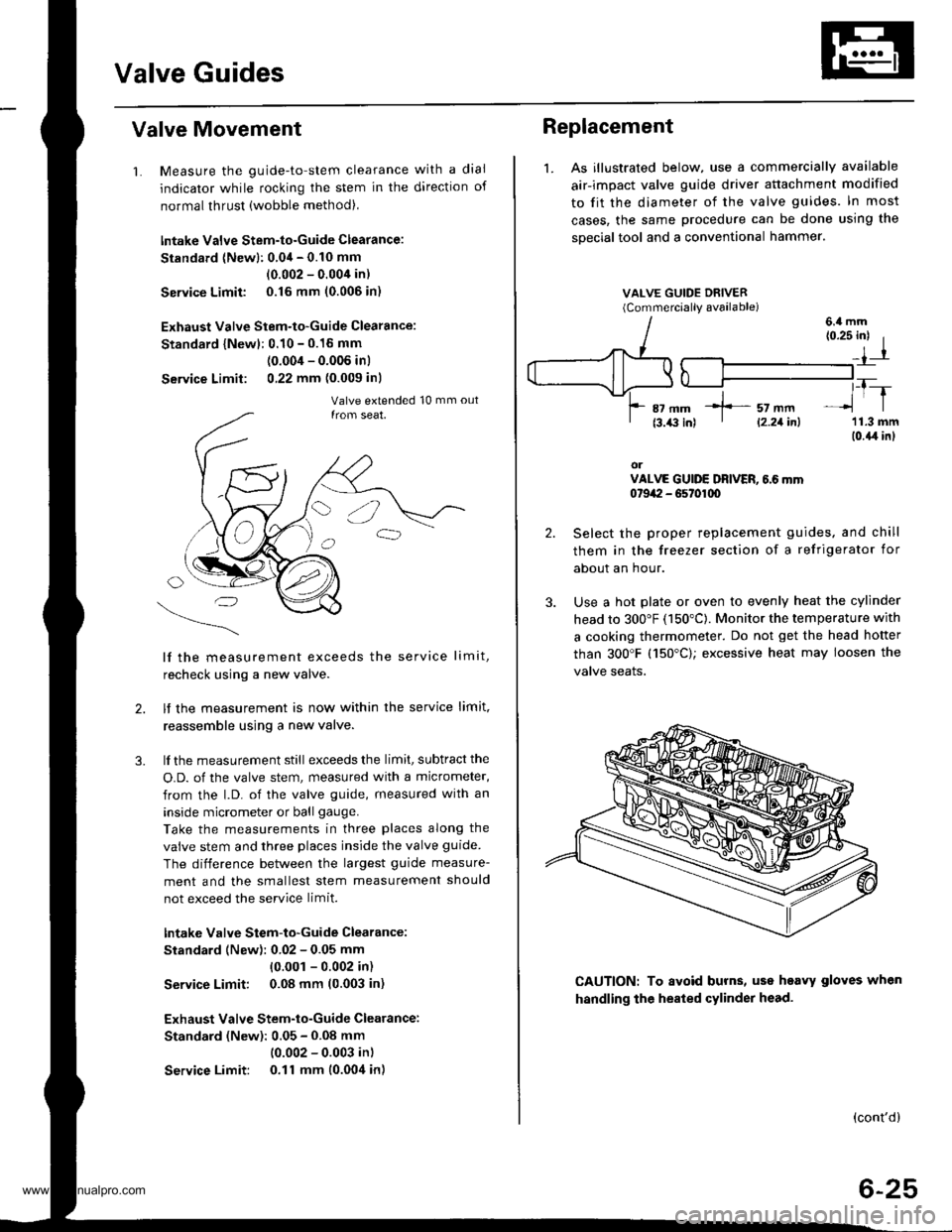
1. Measure the guide-to-stem clearance with a dial
indicator while rocking the stem in the direction of
normal thrust (wobble method),
lntake Valve Stem-to-Guide Clearance:
Standard (Newl: 0.04 - 0.10 mm
(0.002 - 0.004 in)
Service Limit 0.16 mm (0.006 in)
Exhaust Valve Stem-to-Guide Clearance:
Standard {Newl: 0.10 - 0.16 mm
(0.004 - 0.006 inl
Service Limit: 0,22 mm (0.009 inl
lf the measurement exceeds the service limit,
recheck using a new valve.
lf the measurement is now within the service limit,
reassemble using a new valve.
lf the measurement still exceeds the limit, subtract the
O.D. of the valve stem, measured with a micrometer,
from the l.D. of the valve guide, measured with an
inside micrometer or ball gauge.
Take the measurements in three places along the
valve stem and three places inside the valve guide
The difference between the largest guide measure-
ment and the smallest stem measurement should
not exceed the service limit.
lntake Valve Stem-to-Guide Clearance:
Standard (New): 0.02 - 0.05 mm
{0.001 - 0.002 in)
Service Limit: 0.08 mm (0.003 in)
Exhaust Valve Stem-to-Guide Clearance:
Standard (New): 0.05 - 0.08 mm
(0.002 - 0.003 in)
Service Limit: 0.11 mm (0.004 in)
2.
3.
Replacement
1. As illustrated below, use a commercially available
air-impact valve guide driver attachment modified
to fit the diameter of the valve guides. In most
cases, the same procedure can be done using the
sDecial tool and a conventional hammer.
VALVE GUIDE DRIVER(Commerciallv available)
2.
3.
(0.25 inl I
_,1-r
,_T-_lrl
'11.3 mm(0.{,r in}
orVALVE GUIDE DRIVER, 6.6 mm0t9a:I - G5t01q)
Select the proper replacement guides. and chill
them in the freezer section of a refrigerator for
about an hour.
Use a hot plate or oven to evenly heat the cylinder
head to 300"F (150"C). Monitor the temperature with
a cooking thermometer. Do not get the head hofter
than 300'F (150"C); excessive heat may loosen the
valve seaIs.
6.4 mm
CAUTION: To avoid burns, uss heavy gloves when
handling the heated cylinder head.
(cont'd)
6-25
*]-- sz mm' l2.21inl
www.emanualpro.com
Page 158 of 1395
PistonsI
Inspection
LCheck each piston for distortion or cracks.
Measure the piston diameter at distance A from the
bottom of the skirt.
A: '97 - 98 models 15 mm 10.5 inl'99 - 00 models 20 mm 10.8 inl
Piston Diameter:
Standard (New): 8:1.980 - txl.990 mm(3.3063 - 3.3067 inl
Service Limit: 83.970 mm {3.3059 inl
SKIRT DIAMETER
7-12
3. Calculate the difference between the cylinder bore
diameter (see page 7-13) and the piston diameter.
Piston-to-Cylinder Clearance:
Standard {New): 0.010 - 0.040 mm
{0.0004 - 0.0016 inl
Service Limit: 0.05 mm {0.002 in}
lf the clearance is near or exceeds the service limit,
inspect the piston and cylinder block for excessive
wear.
www.emanualpro.com
Page 162 of 1395
Piston Pins
lMeasure the diameter of the piston pin.
Piston Pin Diameter:
Standard lNewl: 20.996 - 21.000 mm
{0.8266 - 0.8268 in}
20.998 - 21.002 mm(0.8267 - 0.8268 in)
Inspection
1.
Oversize:
2. Zeto the dial indicator to the piston pin diameter.
7-16
3. Measure the piston pin to piston clearance. lf the
piston pin clearance is greater than 0.024 mm
(0.0009 inL remeasure using an oversized piston pin.
NOIE: All replacement piston pins are oversize.
Piston Pin-to-Piston Clearance:
Standard lNewl: 0.010 - 0.017 mm
10.0004 - 0.0007 in)
Check the difference betlveen the piston pin diame-
ter and the connecting rod small end diameter.
Piston Pin-to-Connecting Rod Interference:
Standard (New): 0.015 - 0.032 mm(0.0006 - 0.0013 inl
4.
www.emanualpro.com
Page 163 of 1395
Piston Rings
End Gap
2.
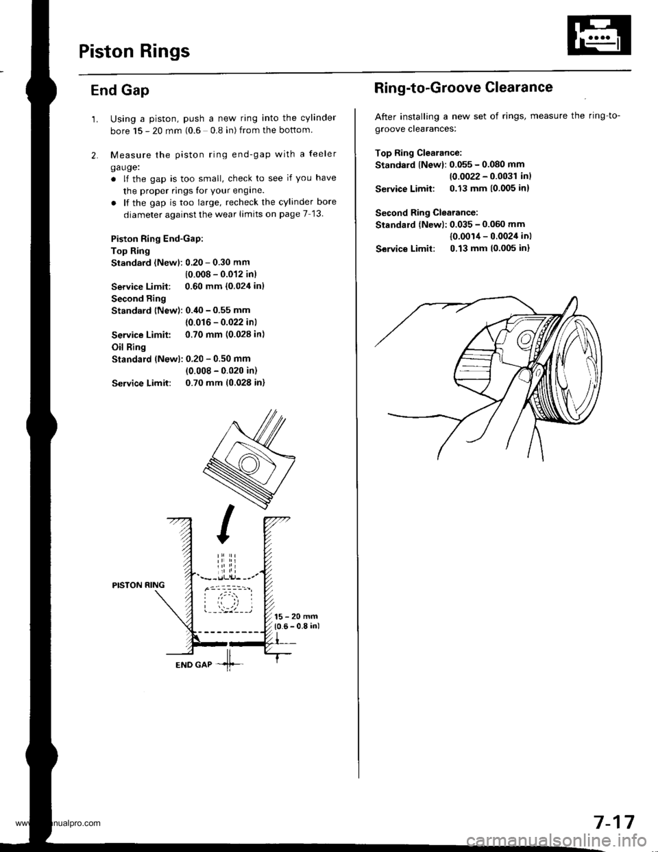
1.Using a piston, push a new ring into the cylinder
bore 15 - 20 mm (0.6 0.8 in) from the bottom
Measure the piston ring end-gap with a feeler
ga uge:
. lf the gap is too small, check to see if you have
the proper rings for your engine.
. lf the gap is too large, recheck the cylinder bore
diameter against the wear limits on page 7 '13.
Piston Ring End-Gap:
Top Ring
Standard (Newl:0.20 - 0.30 mm
10.008 - 0.012 inl
Service Limit: 0.60 mm {0.024 inl
Second Ring
Standard lNew): 0.i10 - 0.55 mm
{0.016 - 0.022 inl
Service Limit: 0.70 mm (0.028 in)
Oil Ring
Standard (Newl: 0.20 - 0.50 mm
10.008 - 0.020 in)
Service Limit: 0.70 mm (0.028 in)
PISTON RING
--:4 llEND GAP -1f-
Ring-to-Groove Glearance
After installing a new set of rings, measure the ring-to-
groove clearances:
Top Ring Clearance:
Standard {New}: 0.055 - 0.080 mm
10.0022 - 0.0031 inl
Service Limit: 0.13 mm 10,005 inl
Second Ring Clearance:
Standard {Newl: 0.035 - 0.060 mm
{0.001'l - 0.0024 inl
Service Limit: 0,13 mm 10.005 inl
7-17
www.emanualpro.com