1999 HONDA CR-V Plug seal
[x] Cancel search: Plug sealPage 681 of 1395
Transfer Assembly
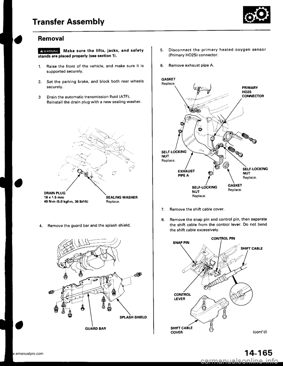
Removal
@ Make sure the lifts, iacks, and safety
stands are placed properly (see section 11.
1. Raise the front of the vehicle, and make sure it is
supported securely.
2. Set the parking brake, and block both rear wheels
securelv.
3 Drain the automatic transmission fluid (ATF).
Reinstall the drain plug with a new sealing washer'
DRAIN PLUG'18 x'1.5 rnm49 N.m 15.0 kgf.m, 36 lbl.ftl
4. Remove the guard bar and the splash shield.
GUARD 8AR
14-165
5.Disconnect the primary heated oxygen sensor
{Primary HO2S) connector.
Remove exhaust pipe A.
SELF-LOCKINGNUTBeplace.
7.
SEI-F.LOCKINGNUTReplace.
NUTReplace
Remove the shift cable cover.
Remove the snap pin and control pin, then separate
the shift cable from the control lever. Do not bend
the shift cable excessively.
(cont'd)
www.emanualpro.com
Page 686 of 1395
Transmission
Removal (cont'd)
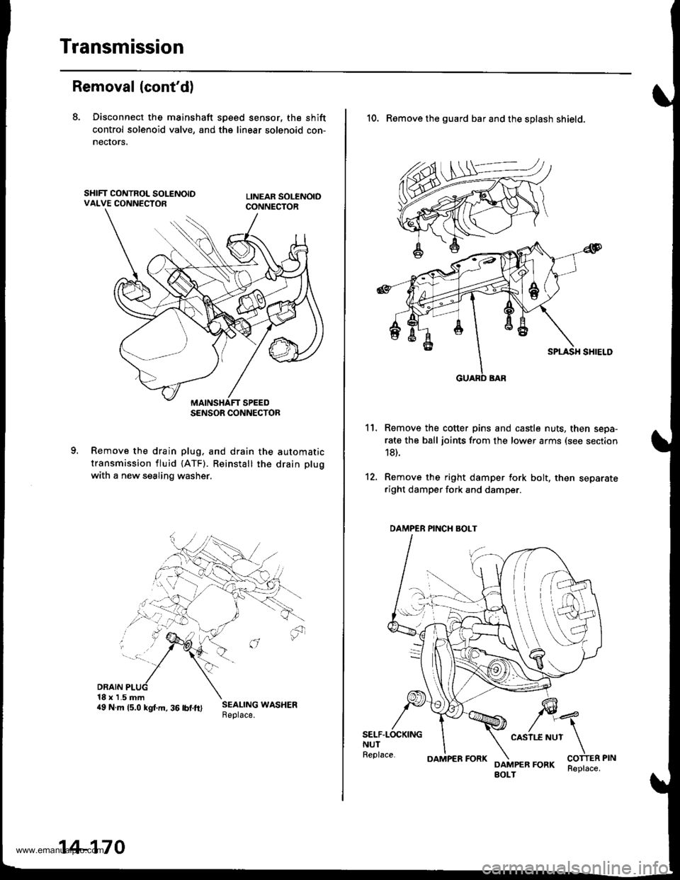
8. Disconnect the mainshaft sp€ed sensor, the shift
control solenoid valve, and the linear solenoid con-
necrors,
Remove the drain plug. and drain the automatic
transmission fluid {ATF). Reinstall the drain plug
with a new sealing washer.
DRAIN18 x 1.5 mm4e N.m rs.o ksr.m. 36 rbrft) ;:i:$: *o"*."
SENSOR CONNECTOR
14-170
OAMPER FORKReplace.
10. Remove the guard bar and the splash shield.
Remove the cotter pins and castle nuts, then sepa-
rate the ball joints from the lower arms (see section
18).
Remove the right damper fork bolt, then separateright damper fork and damper.
11.
12.
SELF.LOCKINGNUTReplace.
CASII.E NUT
DAMPER FORKBOLT
DAMPER PINCH BOLT
www.emanualpro.com
Page 691 of 1395
O END COVER
O olL SEAL Replace.
O BALL BEARING
@ A/T GEAR PoSITIoN swITcH coVER
€) A/T GEAn PosrloN swrrcH
@ ROLLER
O coLLARG) o-RING Replace.{9) FEED PIPE FLANGE
@ O-RING Replace.
O SNAP RING
@ 3RD CLUTCH FEED PIPE(D CoUNTERSHAFT LOCKNUT 23 x 1.25 mm Replace.(} coNtcAL SPR|NG WASHER Reptace.
@ PARK GEAR@ ONE.WAY CLUTCH(, COUNTENSHAFT lST GEAR(D NEEOLE BEARING(O COUNTERSHAFT lST GEAR COLLAR
@ o-RING Reptace.
@ lST CLUTCH FEED PIPE
@ O-RING Reptace.
@} FEEO PIPE FLANGE
@ SNAP RING
@ DOWEL PIN
@ END coVER GASKET Feplace.
@ PARK PAWL SToP@ PARK PAWL
@ PARK PAWL SPRING
@ PARK PAWL SHAFT
O} A/T GEAR POSITION SWITCH HARNESS CLAMP
@ PARK LEVER
@ LOCK WASHER Replace.
@ PARK STOP Selective part
@ PARK LEVER SPRING@ DRAIN PLUG
O SEALING WASHER Reptace.
@) MAINSHAFT LOCKNUT2l x 1.25 mm Replace.@ CONICAL SPRING WASHER Replace.@ lST CLUTCH ASSEMBLY
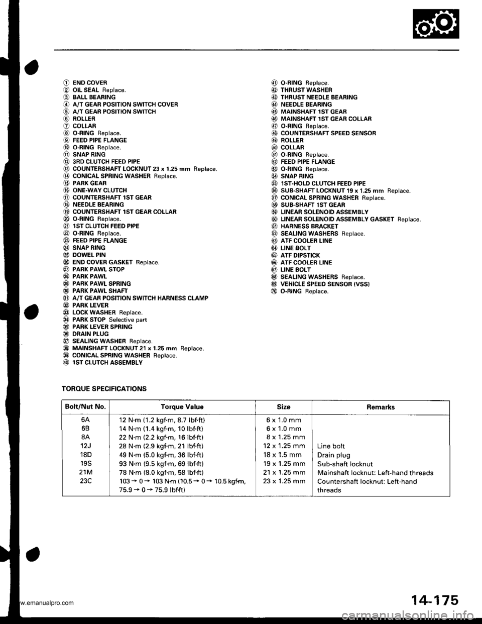
TOROUE SPECIFICATIONS
i!, O-RING Replace.
@ THRUST WASHER
@ THRUST NEEDLE BEARING@ NEEDLE BEARING
@ MAINSHAFI 1ST GEAR@ MAINSHAFT 1sT GEAR coLLAR
@ o-RING Replace.
6!, COUNTERSHAFT SPEED SENSOR@ ROLLER
@) COLLAR@ o-RtNG Replace.
6A FEEo PIPE FLANGE
@ o-RtNG Reptace.
@ SNAP R|NG
@ IST.HOLD cLUTcH FEED PIPE@ SUB-SHAFT LOCKNUT 19 x 1,25 mm Reptace.O coNtCAL SPR|NG WASHER Reptace.E! SUB.SHAFT lST GEAR€} LINEAR SOLENOID ASSEMBLY
@ LTNEAR soLENotD aSSEMBLy GASKET Reptace.
@ HARNESS BBACKET
@ SEALING WASHERS Feptace.
@ ATF COOLER LINE
@ LIN€ BoLT
@ ATF DIPSTICK
@ ATF COOLER LINE
@ LINE BoLT@ SEALING WASHERS Reptace.@ VEHICLE SPEED sENsoR (vss)
@ o-RtNG Beptace.
Bolt/Nut No.Torque ValuoSizeRemarks
6B
8A
12J
18D
19S
21M
23C
'12 N'm ('1.2 kgf.m,8.7 lbf.ft)
14 N.m (1.4 kgf.m, 10lb{.ft}
22 N.m 12.2 kgf.m, 16 lbf.ft)
28 N'm (2.9 kgf.m,21 lbf.ft)
49 N.m (5.0 kgf.m,36 lbf'ft)
93 N'm {9,5 ksim.69 lbf.ft)
78 N.m {8.0 kgnm,58 lbf.ft)
103* 0- 103 N{n {10.5* 0+ 10.5 kgfn,
75.9-0-75.9 lbf{t)
6x 1.0 mm
6x1.0mm
8 x 1.25 mm
12 x 1.25 mm
18 x 1.5 mm
19 x 1.25 mm
21 x 1.25 mm
23 x 1.25 mm
Line bolt
Drain plug
Sub-shaft locknut
Mainshaft locknut: Left-hand threads
Countershaft locknut: Left-hand
threads
14-175
www.emanualpro.com
Page 697 of 1395
![HONDA CR-V 1999 RD1-RD3 / 1.G Workshop Manual
O END COVERiLl OIL SEAL Beplace.
O BALL BEARINGi.) A/T GEAR POSITION SWITCH COVER
i5] A/T GEAR POSITION SWITCH
aq) RoLLER
? COLLABi0 o-BtNG Replace.
€) FEED PIPE FLANGE
f,o) o-RING Replace.
1 SNAP HONDA CR-V 1999 RD1-RD3 / 1.G Workshop Manual
O END COVERiLl OIL SEAL Beplace.
O BALL BEARINGi.) A/T GEAR POSITION SWITCH COVER
i5] A/T GEAR POSITION SWITCH
aq) RoLLER
? COLLABi0 o-BtNG Replace.
€) FEED PIPE FLANGE
f,o) o-RING Replace.
1 SNAP](/manual-img/13/5778/w960_5778-696.png)
O END COVERiLl OIL SEAL Beplace.
O BALL BEARINGi.) A/T GEAR POSITION SWITCH COVER
i5] A/T GEAR POSITION SWITCH
aq) RoLLER
? COLLABi0 o-BtNG Replace.
€) FEED PIPE FLANGE
f,o) o-RING Replace.
1' SNAP RING
1A 3RD CLUTCH FEED PIPE
O COUNTERSHAFT LOCKNUT 23 x 1.25 mm Replace.
[} coNtcal SPRING WASHER Replace.iO PARK GEAR(!I ONE.WAY CLUTCH
E COUNTERSHAFT lST GEAR
@ NEEDLE BEARING
@ COUNTERSHAFT 1ST GEAR COLLAR
Or o-RtNGS Reptace.
?] lST CLUTCH FEED PIPE
@ o-RING Replace.
e3 FEED PIPE FLANGE
4I SNAP RING
€i DOWEL PINi?0 END COVER GASKET Replace.
?7) PARK PAWL STOP
E9 PARK PAWL
C9 PARK PAWL SPRING
€D PARK PAWL SHAFT
OI A/T GEAR POSITION SWITCH HARNESS CIAMP
@ PARK LEVER
€3 LoCK WASHER Replace.
04 PARK sToP Selective part(!' PARK LEVER SPRING
@ DRAIN PLUG
Ot SEALING WASHER Replace.
60 MA|NSHAFT LocKNuT 21 x 1.25 mm Replace.(9 CONICAL SPRING WASHER Replace.
@ lST CLUTCH ASSEMBLY
TOROUE SPECIFICATIONS
,!4! O-RING Replace.
@I THRUST WASHER@ THRUST NEEDLE BEARINGi.!' NEEDLE BEARINGi MAINSHAFT lST GEAR
@i MAINSHAFT 1ST GEAR COLLAR!r, O-RING Replace.iO COUNTERSHAFT SPEED SENSOR
E ROLLER
@, coLLAR
Ct o-RING Replace.5.] FEED PIPE FLANGE
09 o-RING Replace.
6A SNAP RING
5' IST.HOLD CLUTCH FEED PIPE
@-] SUB-SHAFT LOCKNUT 19 x 1.25 mm Replace.
!t CONICAL SPRING WASHER Replace.
6i' SUB-SHAFT lST GEAR
G) LINEAR SOLENOID ASSEMBLY(6!) LINEAR SOLENOID ASSEMBLY GASKET Replace
G] HARNESS BRACKET
6a SEALING WASHERS Replace.
C' ATF COOLER LINE
@ L|NE BoLT
GI ATF DIPSTICK
GI ATF COOLER LINE
O LINE BOLT
@ SEALING wasHERs Replace.aoo VEHICI.E SPEED SENSOR IVSS)
f,E O-RING Replace.
Bolt/Nut No.Torque ValueSizeRemarks
6A
6B
8A
12J'18D
195
21M
12 N.m (1.2 kgf.m,8.7 lbf.ft)
14 N.m (1.4 kgf.m, 10lbf.ft)
22 N.m 12.2 kgim, 16lbf.ft)
28 N.m (2.9 kgim,21 lbf.ft)
49 N'm (5.0 kgim,36 lbf.ft)
93 N.m (9.5 kgf.m,69 lbf.ft)
78 N.m (8.0 kgf.m,58 lbf.ft)
103+ 0+ 103 N{n (10.5 + 0+ 10.5 kSfm,
75.9' 0 - 75.9 lbfft)
6x1.0mm
6x1.0mm
8 x 1.25 mm
12 x 1 .25 mm
18 x 1.5 mm
19 x 1.25 mm
21 x 1.25 mm
23 x 1.25 mm
Line bolt
Drain plug
Sub-shaft locknut
Mainshaft locknut: Left-hand threads
Countershaft locknut: Left-hand
threads
14-181
www.emanualpro.com
Page 810 of 1395

Oil SealsRear Differential Assembly
Replacement (cont'd)
3. Remove the oil seal from the toroue control differ-
ential case.
Install the oil seal squarely using the special tool.careful not to damage the lip of the oil seal.
15-20
BREATHER TUBE
DRAIT{ PLUG
Disassembly
1. Remove the breather tube, the drain plug and the oilfiller plug.
OIL FILI.IR PLUG
Raise the locknut tab from the groove of the clutchguide, making sure that the tab completelv clearsthe groove to prevent damaging the clutch guide.
L(rcKNUT, 24 mmReplace.
www.emanualpro.com
Page 877 of 1395
Power Steering Gearbox
AN'USTABLE HOSE CLAMP
Removal (cont'dl
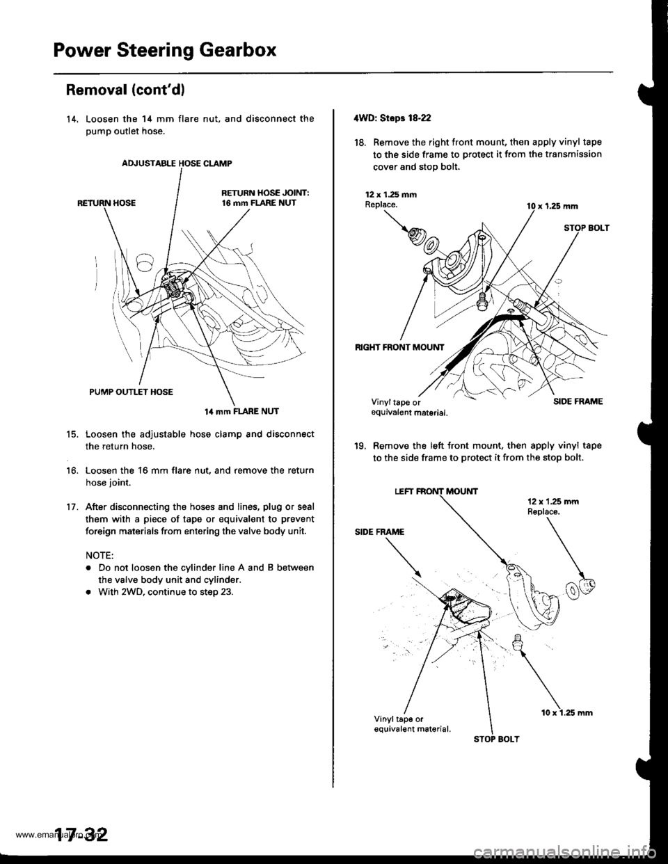
14. Loosen the 14 mm flare
pump outlet hose.
nut, and disconnect the
14 mm FLARE NUT
15. Loosen the adjustable hose clamp and disconnect
the return hose,
16. Loosen the 16 mm flare nut, and remove the return
hose joint.
17. After disconnecting the hoses and lines, plug or seal
them with a piece of tape or equivalent to prevent
foreign maisrials from entering the valve body unit.
NOTE:
. Do not loosen the cylinder line A and B between
the valve body unit and cylinder.
. With 2WD, continue to step 23.
17 -32
STOP BOLT
10 x 1.25 mm
4WD: Stepr 18-22
18. Removethe right tront mount, then apply vinyl tape
to the side frame to protect it from the transmission
cover and stop bolt.
12 x 1.25 fiiAReplace.
RIGHT FRONT MOUNT
x 1,25 mm
SIDE FRAME
'19. Remove the left front mount, then apply vinyl tape
to the side frame to protect it from the stop bolt.
Vinyltape orequivalgnt material.
Vinyltap€ orequival€nt m6terial.
www.emanualpro.com
Page 1138 of 1395
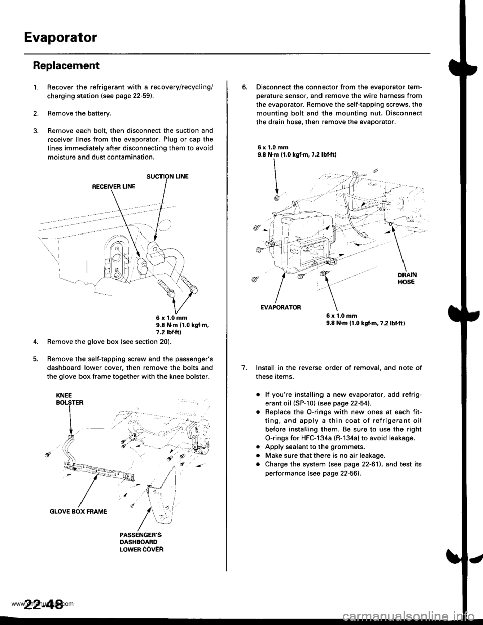
Evaporator
Replacement
1.Recover the refrigerant with a recovery/recycling/
charging station (see page 22-59).
Remove the battery.
Remove each bolt, then disconnect the suction and
receiver lines from the evaporator. Plug or cap the
lines immediately after disconnecting them to avoid
moisture and dust contamination,
RECEIVER LINE
..
\
6x1.0mm9.8 N'm (1.0 kgf m,7.2 tbl.ttl
Remove the glove box (see section 20).
Remove the self-tapping screw and the passenger's
dashboard lower cover, then remove the bolts and
the glove box frame together with the knee bolster.
GLOVE BOX FRAME
KNEE
22-44
6. Disconnect the connector from the evaoorator tem-
oerature sensor. and remove the wire harness from
the evaporator. Remove the self-tapping screws, the
mounting bolt and the mounting nut. Disconnect
the drain hose, then remove the evaporator.
5xl,0mm9.8 N.m {1.0
II
I
Io
kgf.m, 7.2 lbf.ftl
, -l: "
7.
EVAPORATOR
6x1.0mm9.8 N.m (1.0 kgtm,7.2lbf.ftl
Install in the reverse order of removal, and note of
these items.
. lf you're installing a new evaporator, add refrig-
erant oil (SP.10) (see page 22-541.
Replace the O-rings with new ones at each fit-
ting, and apply a thin coat of refrigerant oil
before installing them. Be su.e to use the right
O-rings for HFC-134a (R-134alto avoid leakage.
Apply sealant to the grommets.
Make sure that there is no air Ieakage.
Charge the system (see page 22-6'll, and test its
performance (see page 22-56]-,
a
a
a
www.emanualpro.com
Page 1144 of 1395
A/C Service Tips and Precautions
The air conditioner system uses HFC-'134a (R-134a) refrigerant and polyalkyleneglycol {PAG) refrigerant oil*, which are not
compatible with CFC-12 (R-12) refrigerant and mineral oil. Do not use R-12 refrigerant or mineral oil in this system, and do
not attempt to use R-12 servicing equipmenu damage to the air conditioner system or your servicing equipment will
resutr.
*KEIHIN SP-10:
. P/N 38897 - Pl3 - A01AH: 120 m{ (4 fl.oz, il.2 lmp.oz)
. P/N 38899 - Pl3 - A01: 40 mf 11113tl.oz,1.4 lmp.oz)
Use only service equipment that is U.L.-listed and is certified to meet the requirements of SAE J2210 to remove R-134a
from the air conditioner system,
CAUTION: Exposure to air conditioner refrigerant and lubricant vapor or misl can irritats eyes, nose and throat. Avoid
breathing the air conditioner refrigerant and lubricant vapor or mist,
lf accidental system discharge occurs, ventilate work area before resuming service.
R 134a service equipment or vehicle air conditioner systems should not be pressure tested or leak tested with compressed
air.
E@ Some mixtures of air and R-13,1a have been shown to be combustible at elevat€d pressures and can result
in fire or explosion causing iniury or property damage. Never use complessed air to pressure test R-l3,[a service equip-
ment or vehicle air conditioner systems.
Additional health and safety information may be obtained from the refrigerant and lubricant manufacturers.
1. Always disconnect the negative cable from the battery whenever replacing air conditioning parts.
2. Keep moisture and dust out of the system. When disconnecting any lines, plug or cap the fittings immediately; don't
remove the caps or plugs until just before you reconnect each line.
3. Before connecting any hose or line. apply a few drops of refrigerant oilto the O-ring,
4. When tightening or loosening a fitting, use a second wrench to support the matching fitting.
5. When discharging the system, use a R l34a refrigerant recovery/recycling/charging station; don't release refrigerant
into the atmosphere.
6. Add refrigerant oil after replacing the following parts.
Note these items when handling refrigerant oil:
o To avoid contamination, do not return the oil to the container once dispensed, and never mix it with other refriger-
ant oils.
. lmmediately after using the oil, replace the cap on the container, and seal it to avoid moisture absorption.
. Do not spill the refrigerant oil on the vehicle; it may damage the painu if the refrigerant oil contacts the paint, wash
it off immediately.
Condenser . 25 ml (5/6 tl.oz, 0.9 lmp.oz)
Evaporator.,................................40 m/ 11 113ll.oz,l.4 lmp.ozl
Line or hose ........... 10 ml (1/3 fl.oz, 0.4 lmp.oz)
Receiver/Dryer....... 10 ml (1/3 fl.oz, 0.4 lmp.oz)
Leakage repair............................ 25 m/ (5/6 ll.oz, 0.9 lmp.oz)
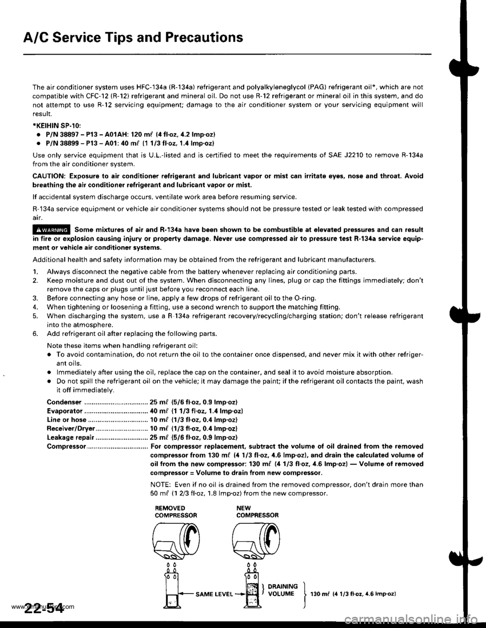
Compressor.......,..., For compressor replacement, subtract the volumg ol oil drained from the removed
compressor from 130 m{ (4 113 tl.oz, 1,6lmp.ozl, and drain the calculatsd volume of
oif from the now comprossor: 130 ml (,1 113 tl,oz, 1.6lmp'ozl - Volume of removed
compressor = Volume to drain from new compressor.
NOTE: Even if no oil is drained trom the removed compressor, don't drain more than
50mt 11 213ll,oz,1.8 lmp.oz) from the newcompressor.
22-54I
rso m r rr:0.o., r.s r-o.o.t
www.emanualpro.com