1999 HONDA CR-V Front window
[x] Cancel search: Front windowPage 66 of 1395

lgnition System
5.
lgnition Timing Inspection and Setting
2.
1.Check the idle speed, and adjust it if necessary (see
section 1 1).
Pull out the service check connector 2P (BRN and
BLK wires) from the connector holder located under
the dash on the front passenger side, then connect
the scs service connector (P/N 07PAz - 0010100) to
it.
Start the engine. Hold the engine at 3,000 rpm with
no load (A/T in N or E, Mff in neutral) until the
radiator fan comes on, then let it idle.
Connect the timing light to the No. I ignition wire,
then point the light toward the pointer on the timing
belt cover.
Check the ignition timing in no load conditions:
headlights, blower fan, rear window defogger, and
air conditioner are not operating.
lgnition Timing:
M/T: 16" 12" BTDC (RED) idling in neutral
AlTt'16" !2" BTDC (RED) idling in E or E
CRANKSHAFTPULLEY
4-16
6. lf necessary, adjust the ignition timing as follows.
Loosen the distributor mounting bolts, and turn the
distributor ignition (Dl) housing counterclockwise to
advance the timing or clockwise to retard the tim-
t no,
7.
8.
MOUNTING BOLTS24 N.m {2.4 kgf m, 17 lbtft}
Tighten the distributor mounting bolts, and recheck
the ignition timing.
Disconnect the SCS service connector from the ser-
vice check connector.
To RETARD
www.emanualpro.com
Page 982 of 1395
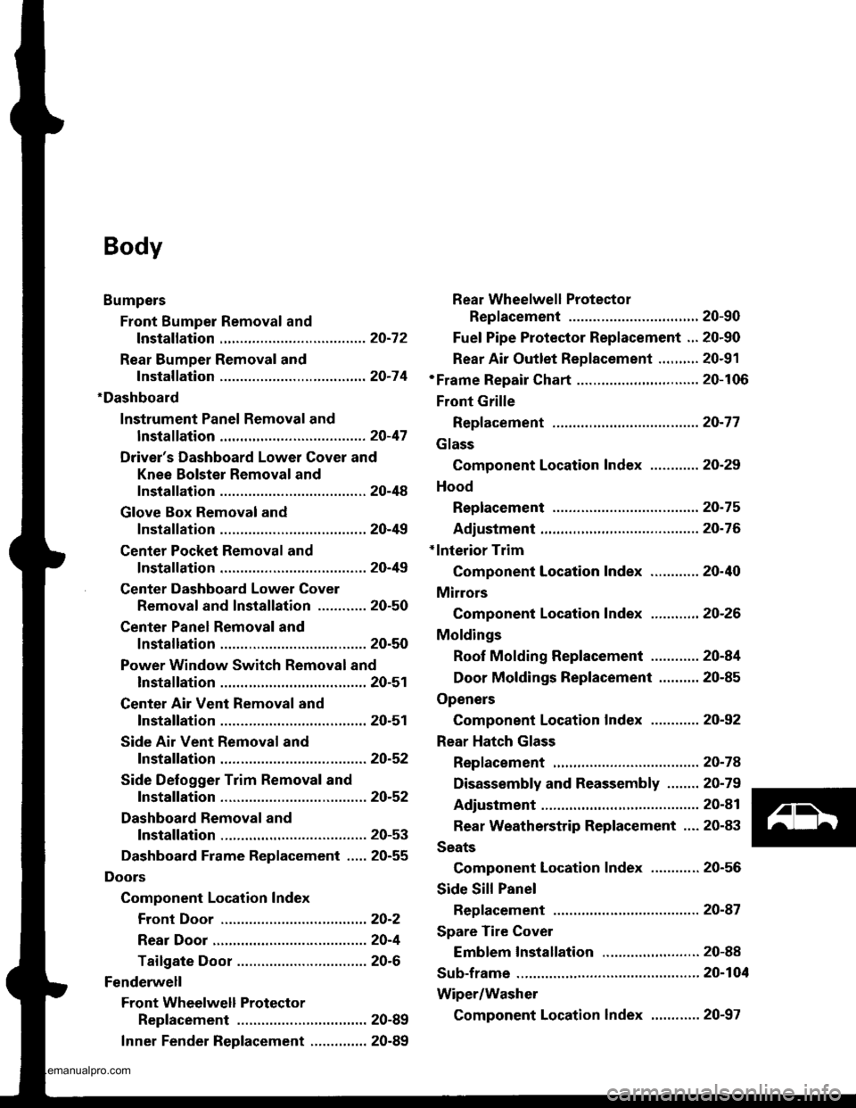
Body
Bumpers
Front Bumper Removal and
fnstaflation .........20-72
Rear Bumper Removal and
fnstaflation .........20-74
'Dashboard
lnstrument Panel Removal and
lnstallation .........20-47
Driver's Dashboard Lower Cover and
Knee Bolster Removal and
Installation .........20-48
Glove Box Removal and
lnstallation .........20-49
Center Pocket Removal and
lnstallation .........20-49
Center Dashboard Lower Cover
Removal and lnstallation ............ 20-50
Center Panel Removal and
lnstallation .........20-50
Power Window Switch Removal and
lnstallation .........20-51
Center Air Vent Removal and
lnstallation .........20-51
Side Air Vent Removal and
fnstallation .........20-52
Side Defogger Trim Removal and
fnstallation .........20-52
Dashboard Removal and
lnstallation .........20-53
Dashboard Frame Replacement ..... 20-55
Doors
Component Location Index
Front Door ,,...,,,,20-2
Rear Door ...........20-4
Tailgate Door ................................ 20-6
Fenderwell
Front Wheelwell Protector
Replacement .....20-89
Inner Fender Replacement .,.....,.,.... 20-89
Rear Wheelwell Protectol
Replacement .....20-90
Fuel Pipe Protector Replacement ... 20-90
Rear Air Outlet Replacement .......... 20-91
*Frame Repair Chart .............................. 20-106
Front Grille
Repf acement .........20-77
Glass
Component Location Index ............ 20-29
Hood
Replacement ......,,,20-75
Adjustment ............20-76
*lnterior Trim
Component Location Index ............ 20-40
Mirrors
Component Location Index .........,,, 20-26
Moldings
Roof Molding Replacement ............ 20-84
Door Moldings Replacement .......... 20-85
Openers
Component Location Index ............ 20-92
Rear Hatch Glass
Replacement .........20-74
Disassembly and Reassembly ........ 20-79
Adiustment ............20-81
Rear Weatherstrip Replacement .... 20-83
Seats
Component Location Index ............ 20-56
Side Sill Panel
Repfacement .........20-87
Spare Tire Cover
Emblem Installation ........................ 20-88
Sub-frame ..................20-104
Wiper/Washer
Component Location lndex ,,,,,....... 20-97
www.emanualpro.com
Page 986 of 1395
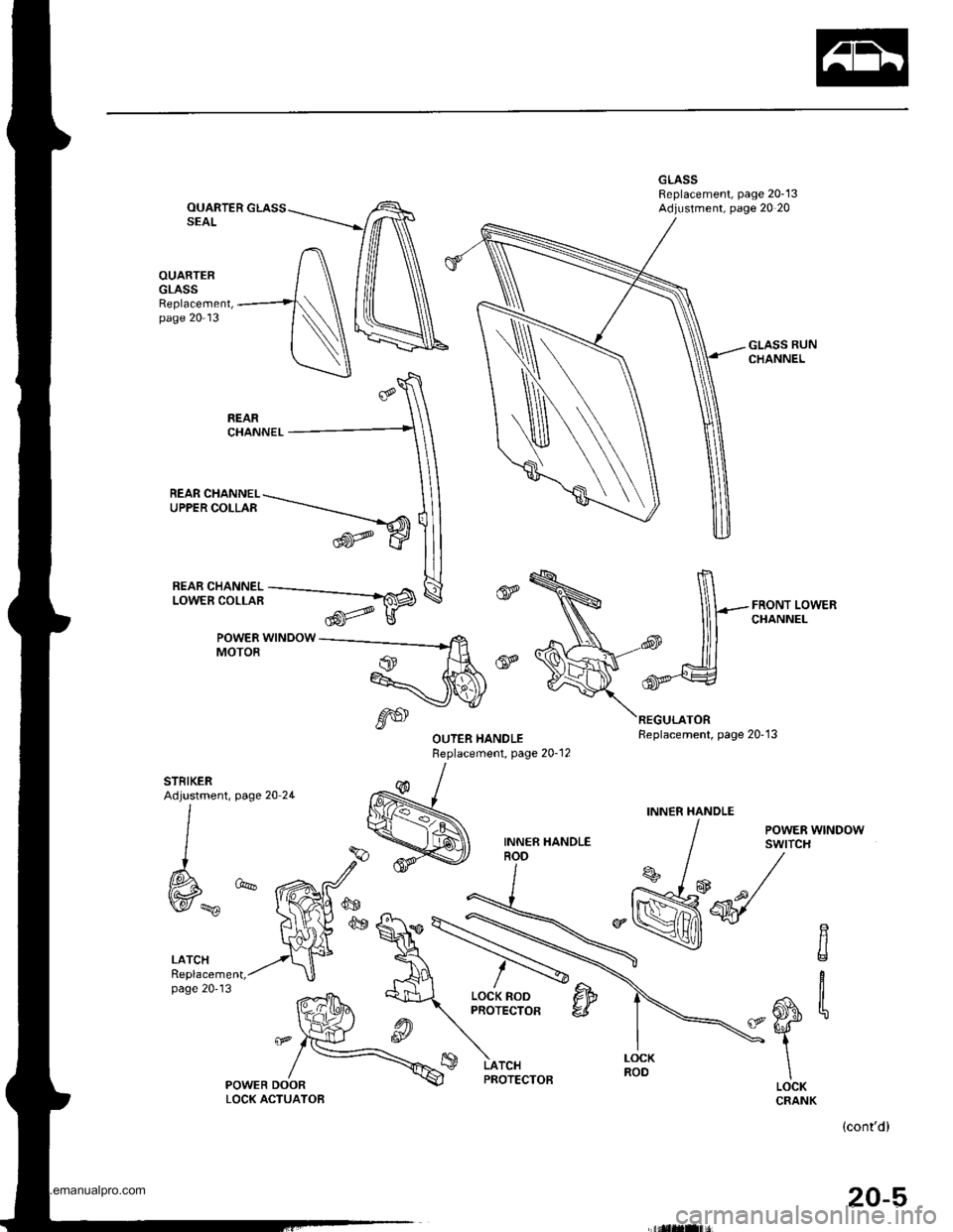
OUARTERSEAL
OUARTERGLASSReplacement,page 20-13
-flHiili^'i--_Fffi
POWER WINDOWMOTOR
REAR CHANNEL-\UPPERCOLLAR -.-----_----_-""
trw
page 20 2L
LATCHReplacement,page 20'13
POWEB DOORLOCK ACTUATOB
,6S
REGULATORReplacement, page 20'13
GLASS RUNCHANNEL
FRONT LOWERCHANNEL
STRIKERAdjustment,
l
I
W*
INN€R HANDLE
/ eowea wrruoow
I sYtfcH
s /* /
M-q/-\
LOCK RODPROTECTORCItr'6,1-
iI
\LOCKCRANK
LATCHPROTECTOB
(cont'd)
20-5
www.emanualpro.com
Page 991 of 1395
Doors
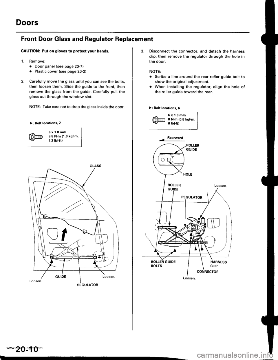
Front Door Glass and Regulator Replacement
CAUTION: Put on gloves to protect your hands,
1. Remove;
. Door panel (see page 20-7)
. Plastic cover (see page 20-21
2. Carefully move the glass until you can see the bolts,
then loosen them. Slide the guide to the front, then
remove the glass from the guide. Carefully pull the
glass out through the window slot.
NOTE: Take care not to drop the glass inside the door.
>: Bolt locations,2
6xl.0mm9.8Nm(1.0kgt.m.7.2 tbt.ftl
GLASS
REGULATOR
20-10
3. Disconnect the connector, and detach the harness
clip, then remove the regulator through the hole in
the door.
NOTE:
. Scribe a line around the rear roller guide bolt to
show the original adjustment.
. When installing the regulator, align the hole of
the roller guide toward th€ rear.
>: Bolt locations,6
6x1.0mm8 N.m {0.8 kgt.m,6 rbtft)
Roaru/ard
Loosen,
www.emanualpro.com
Page 1080 of 1395
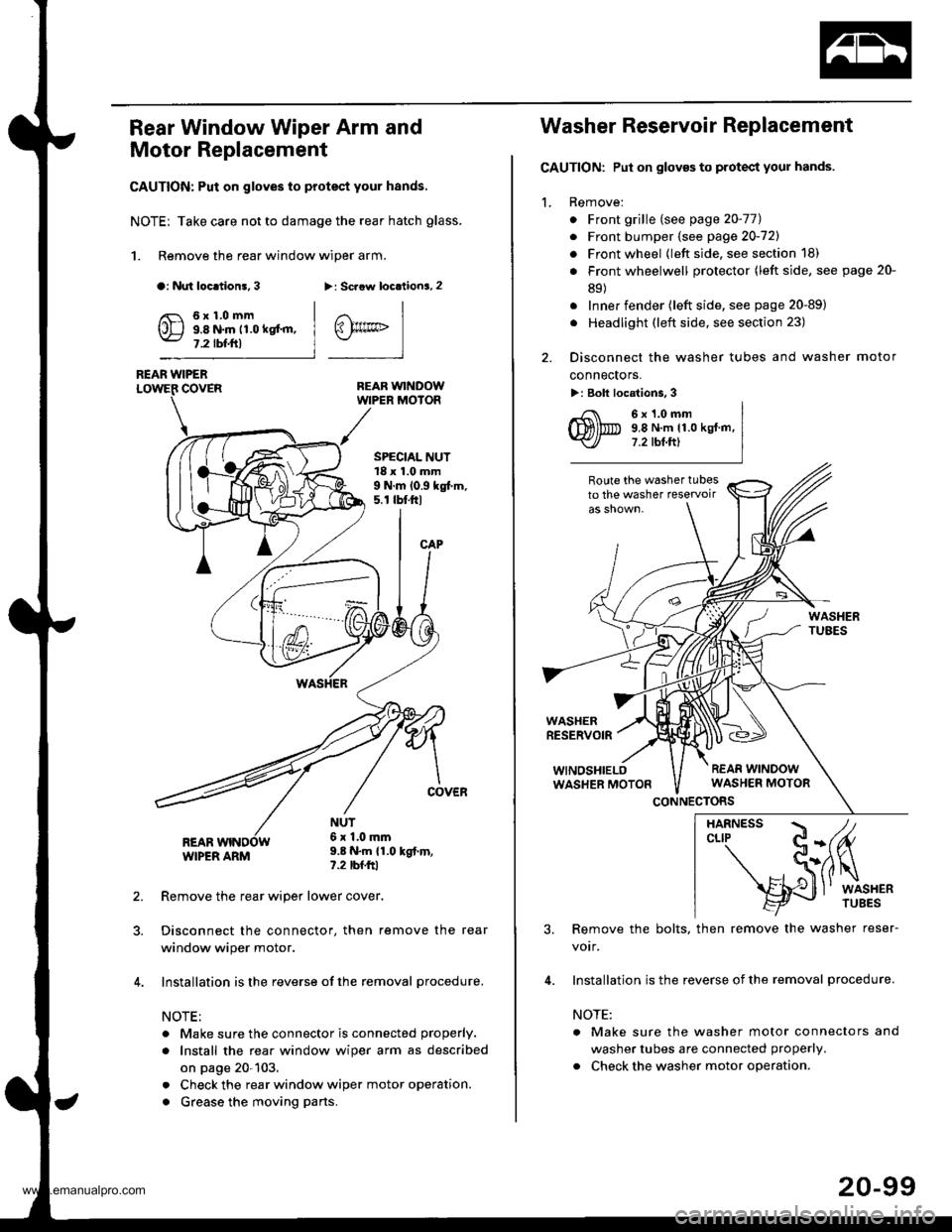
Rear Window Wiper Arm and
Motor Replacement
CAUTION: Put on gloves to protect your hands.
NOTE; Take care not to damage the rear hatch glass.
1. Remove the rear window wiper arm.
a: Nut loc.tion!, 3>: Scaow locationa, 2
REAR WINDOWWIPER MOIOR
REAR WIPERCOVER
REARWIPER ARM
6x1.0mm9.8 N.m 11.0 kgt'm,7.2 tbf.ftl
SPECIAL NUT18 x 1.0 mm9 N.m 10.9 kgt m,5. r tbt.ftl
NUT6x 1.0mm9.8 N.m {1.0 kgt.m,?.2 tbfftl
Remove the rear wiper lower cover.
Disconnect the connector, then remove the rear
window wiper motor.
Installation is the reverse of the removal procedure.
NOTE:
. Make sure the connector is connected properly.
. Install the rea. window wiper arm as described
on page 20-103.
. Check the rear window wiper motor operation.
. Grease the moving parts.
@rrc
Washer Reservoir Replacement
GAUTION: Put on gloves to protect your hands.
1. Remove:
. Front grille (see page 20-771
. Front bumper (see page 20-721
. Front wheel {left side, see section 18)
. Front wheelwell protector (left side, see page 20-
89)
. Inner fender (left side, see page 20-89)
. Headlight (left side, see section 23)
2. Disconnect the washer tubes and washer motor
connectors.
>: Bolt locations, 3
6x1.0mm9,8 N.m 11.0 kgt.m,7.2 tbt.ftl
Route the washer tubesto the washer teservoir
WASHERRESERVOIR
WINOSHIELOWASHER MOTON
CONNECTORS
3. Remove the bolts, then remove the washer reser-
votr,
4. Installation is the reverse of the removal procedure.
NOTE:
a Make sure the washer motor connectors and
washer tubes are connected properly.
. Check the washer motor operation.
HARNESS / tcLrP C-(fu
- S(ilq
s{J
l' wrsHER
20-99
www.emanualpro.com
Page 1082 of 1395
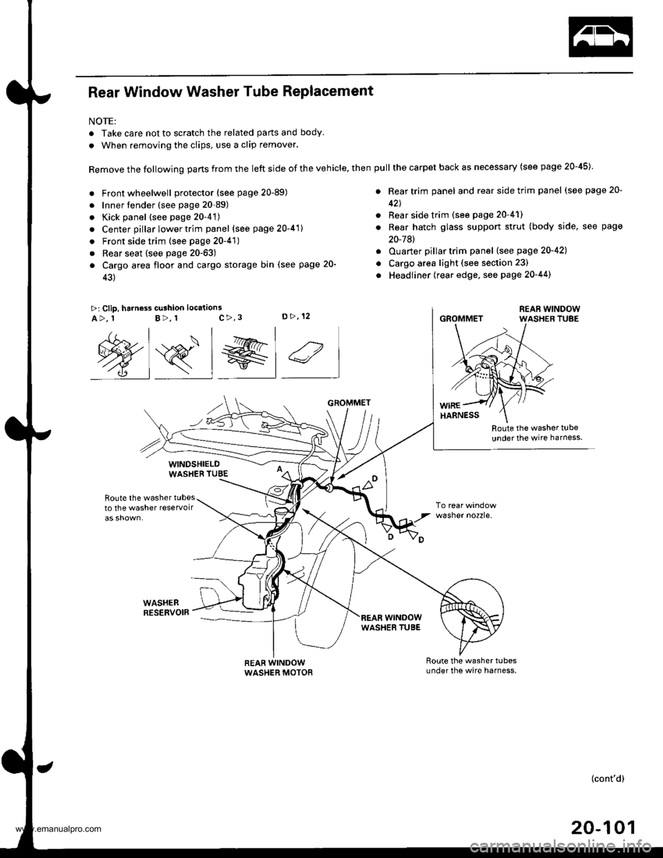
Rear Window Washer Tube Replacement
NOTE:
. Take care not to scratch the related parts and body.
. When removing the clips, use a clip remover.
Remove the following parts from the left side of the vehicle, then
. Front wheelwell protector (see page 20-89)
. Innertender (see page 20-89)
. Kick panel (see page 20-4't)
. Center pillar lower trim panel (see page 20-41)
. Front side trim (see page 20-41)
. Rear seat (see page 20-63)
a Cargo area floor and cargo storage bin (see page 20-
43)
>: Clip, harness cu3hion location3c>,3D>,12A>, 1B>, 1
Route the washer t!be
under the wire harness
Route the washer tubesto the washer reservoir
WASHEBRESERVOIR
wasner no2zre.
@s_l el 4
WINDSHIELDWASHEB TUBE
REAR WINDOWWASHER MOTOR
GROMMET
wrNoowWASHER TUBE
pull the carpet back as necessary (see page 20-45)
. Rear trim panel and rear side trim panel (see page 20-
42J
. Rear side trim (see page 20-41)
. Rear hatch glass support strut (body side, see page
20-7Al
. Ouarter pillartrim panel (see page 20-421
o Cargo area light (see section 23)
. Headliner (rear edge, see page 20-44)
GROMMET
(cont'd)
20-101
www.emanualpro.com
Page 1176 of 1395
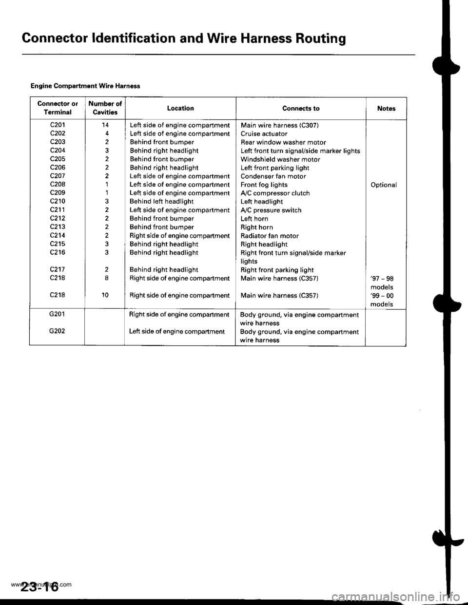
Gonnector ldentification and Wire Harness Routing
Engine Compartment Wire Harness
Connector ol
Terminal
Number of
CavitiesLocationConnects toNotes
c20'l
c202
c203
c204
c205
c206
c207
c208
c209
c210
c212
c213
c2't4
c215
c216
c217
c21A
c218
14
2
2
1'l
2
10
Left side of engine compartment
Left side of engine compartment
Behind front bumper
Behind right headlight
Behind front bumper
Behind right headlight
Left side of engine compartment
Left side of engine compartment
Left side of engine compartment
Behind left headlight
Left side of engine compartment
Behind front bumper
Behind front bumper
Right side of engine compartment
Behind right headlight
Behind right headlight
Behind right headlight
Right side of engine compartment
Right side of engine compadment
Main wire harness (C307)
Cruise actuator
Rear window washer motor
Left front turn signal/side marker lights
Windshield washer motor
Left front parking light
Condenser fan motor
Front fog lights
IVC compressor clutch
Left headlight
IVC pressure switch
Left horn
Right horn
Radiator fan motor
Right headlight
Right front turn signal/side marker
lights
Right front parking light
Main wire harness 1C357)
Main wire harness (C357)
Optional
'97 - 98
models'99 - 00
mooets
G201
G202
Right side of engine companment
Left side of engine compartment
Body ground, via engine compartment
wire harness
Body ground, via engine compartment
wire harness
23-16
www.emanualpro.com
Page 1180 of 1395

Connector ldentification and Wire Harness Routing
Main Wire Harn€ss (left side of dash and floor branchesl {cont,dl
c401
c402
c403
c404
c404
c405
c406
c407
c408
c409
c410
c410
c411
c412
c413
c413
c414
c415
c416
c416
c417
c418
c419
c420
c420
c421
c422
c423
c424
c425
c42A
c426
c437
c438
c438
c439
c440
c441c442
5
20
20
24
't4
8
5
3
12
10'1
18
20'18
10
15
1
4
8
5
5
22
Behind left kick panel
Behind left kick panel
Behind left kick panel
Behind left kick panel
Behind left kick panel
Under left side of dashUnder left side of dashUnder left side of dashUnder left side of dashUnder left side of dashUnder left side of dashUnder left side of dash
Under left side of dashUnder left side of dashUnder left side of dash
Under left side of dash
Under left side of dashUnder left side of dashUnder left side of dashUnder left side of dashUnder left side of dashUnder left side of dashUnder left side of dashUnder left side of dash
Under left side of dashUnder left side of dashUnder left side of dashUnder middle of dashUnder middle of dashUnder middle of dashUnder middle of dashUnder middle of dash
Under left side of dashUnder left side of dash
Under left side of dashUnder left side of dashUnder left side of dashUnder left side of dashUnder left side of dash
Under left side of dash
Under left side of dashUnder left side of dashUnder left side of dashUnder left side of dash
Starter cut relay
Horn relay
Left side wire harness (C558)
Left side wire harness (C559)
Left side wire harness (C559)
Cruise control unitDaytime running lights control unitDaytime running lights control unitlgnition key light control unitInterior wire harness {C701)Cable reel
Cable reel
lgnition key switchlgnition key switch
Combination switch sub-harness {C753)
Combination switch sub-harness (C753)
SRS main harness (C803)
Dashboard wire harness (C503)
Dashboard wire harness (C501)
Dashboard wire harness {C501)Under-dash fuse/relay box (C922)
Under-dash fuse/relay box (C920)
Under-dash fuse/relay box (C919)
lntegrated control unit
Integrated control unitFront fog lights switchBrake switch
Interlock control unitReverse relay
Rear accessory socket relayRear accessory socket relayRear heated oxygen sensor sub-harness (C722)
Security control unitSecurity starter cut relay (for securityalarm system)
Junction connector (for interlock system)Security wire harnessSecurity wire harnessRear window wiper control unitCombination switch sub-harness (C760)
Combination switch sub-harness (C760)
Securlty indicatorSecurity valet switchClutch interlock switchClutch switch (for cruise control)
'97 model'98 - 00mooets
Canada
Canada'97 model
'97 model'98 - 00models
'97 - 98models'99 - 00
moqets
'97 model'98 - 00mooets
Optional
Optional
Optional
Optional
Optional'97 model
'97 - 98mooels'99 - 00models
OptionalOptional
Mfi
Mlr
Under left side of dashBody ground, via main wire harness
23-20
www.emanualpro.com